TX-SR803/E
SERVICE PROCEDURES
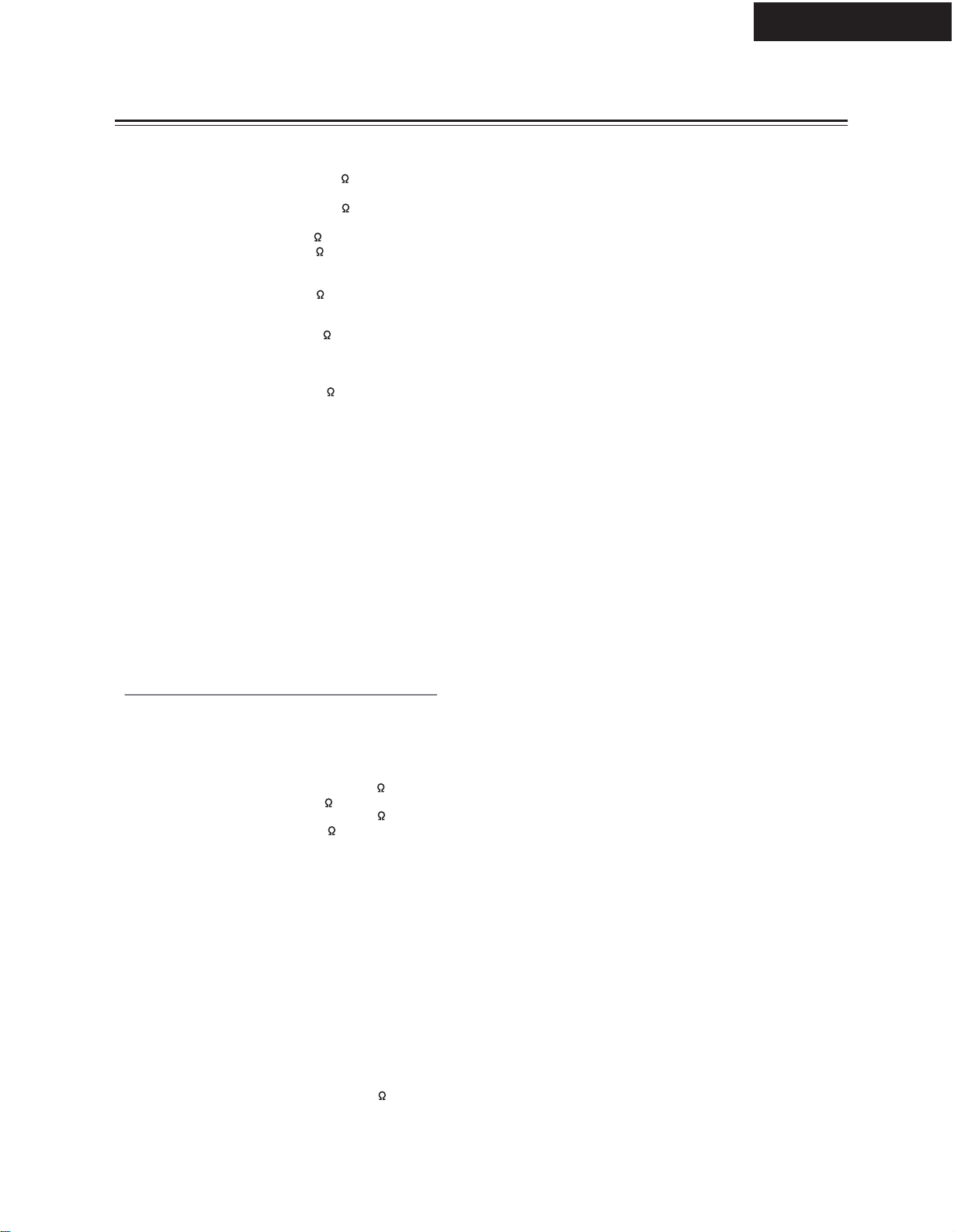
1. Replacing the fuses
This symbol located near the fuses indicates that the
fuse used is fast operating type. For continued protection against
fire hazard, replace with same type fuse. For fuse rating refer to
the marking adjacent to the symbol.
Ce symbole indique que le fusible utlise est a rapide.
Pour une protection permanente, n'untiliser que fusibles de
meme type. Ce darnier est la qu le present symbol est
appse.
CIRCUIT NO. PART NO. DESCRIPTION
2. To initialize the unit
This device employs a microprocessor to perform various
functions and operations. If interference generated by an external
power supply, radio wave, or other electrical source results in
accident which causes the specified operations and functions to
operate abnormally.
To perform a result, please follow the procedure below.
1.Press and hold down the VIDEO-1 button, then press the
STANDBY button.
2.After "CLEAR" is displayed, the preset memory and each
mode stored in the memory, such as surround, are
initialized and will return to the factory setting.
Note: <D>:120V model only
<P>: European model only
<GT>: Asian model only for 230V
<DT>:Asian model only for 120V
<R>: Chinese model only
<K>: Korean model only
3. Safty-check out
(U.S.A. model only)
After correcting the original service problem, perform the
following safety check before releasing the set to the customer.
Leakage Current Check
Measure leakage current to a known earth ground(water pipe,
conduit, etc.) by connecting a leakage current tester between
the earth ground and exposed metal parts of the appliance
(input/output terminals, screwheads,metal overlays, etc.).
Plug the power supply cord directly into a 120V AC 60 Hz outlet
and turn Standby switch on. Any current meausred must not
exceed 0.5mA.
TX-NR1000/5000E
"Not available with Headphones use"
Operation not allowed while a pair of headphones is con-
nected.
"Not available in this Sp Config"
Doesn'
t w
ork with the current speaker configuration.
"Only available with Dolby D"
Can be used with only Dolby Digital.
"Not available with this signal"
Doesn' t work with the current listening mode.
"Not available with Muting"
Operation not allowed because the TX-NR1000/
TX-NR5000 is currently muted.
"Not available in this Listening Mode"
Doesn' t work with the current listening mode.
"Not available with NET AUDIO use"
Operation not possible with Net Audio selected for the
input source.
"Not available with Dolby Headphone Off
Doesn' t work with the Dolby Headphone function off.
"Not available with Dolby Headphone On"
Doesn' t work with the Dolby Headphone function on.
Not available with zone2 out in Line out"
"
Operation not possible with "1-8. f. Zone 2 Out" set to
"Line Out."
Not available with zone3 out in Line out"
Operation not possible with "1-8. g. Zone 3 Out" set to
"Line Out."
4. Error Messages
"
"
5.Memory backup
The TX-NR1000/5000E uses a battery-less memory backup
system in order to retain radio presets and other settings
when it is unplugged or in the case of a power failure.
Although no batteries are required, the TX-NR1000/5000E
must be plugged into an AC outlet in order to charge the
backup system.
(On other than USA, Canadian, and Australian models,
the TX-NR1000/5000E's Power switch must be set to On in
order to charge the backup system). Once it has been
charged, the TX-NR1000/5000E will retain the settings for
several weeks, although this depends on the environment
and time will be shorter in humid climates..
F6911,F6913 252304 20A-UL-250V,Fuse
F6921,F6923 252304 20A-UL-250V,Fuse
F9001 252099 8A-EAK,Fuse <P/GT/R/K>
252303 or 15A-TUL-250V or
252197 15A-UL/T-314,Fuse <D/DT>
F9002 252164 or 5A-UL/T-237 or
252258 5A-T/UL-ST2,Fuse <D/DT>
252241 or 2.5A-SE-TL250V or
252075 or 2.5A-SE-EAK or
252275 2.5A-SE-TL250V,Fuse <P/GT/R/K>
F9501,F9502 252198 or 8A-UL or
252261 8A-T/UL-ST2,Fuse <D>
252260
252079 or
6.3A-T/UL-ST2,Fuse <DT>
6.3A-SE-EAK or
252245 or 6.3A-SE-TL250V or
252166 or
252279
6.3A-UL/T-237 or
6.3A-SE-TL250V,Fuse <P/GT/R/K>
F9503,F9504 252160 or 2.5A-UL/T-237 or
252254 2.5A-T/UL-ST2,Fuse <D/DT>
252075 or 2.5A-SE-EAK or
252241 or 2.5A-SE-TL250V or
252275 2.5A-SE-TL250V,Fuse <P/GT/R/K>


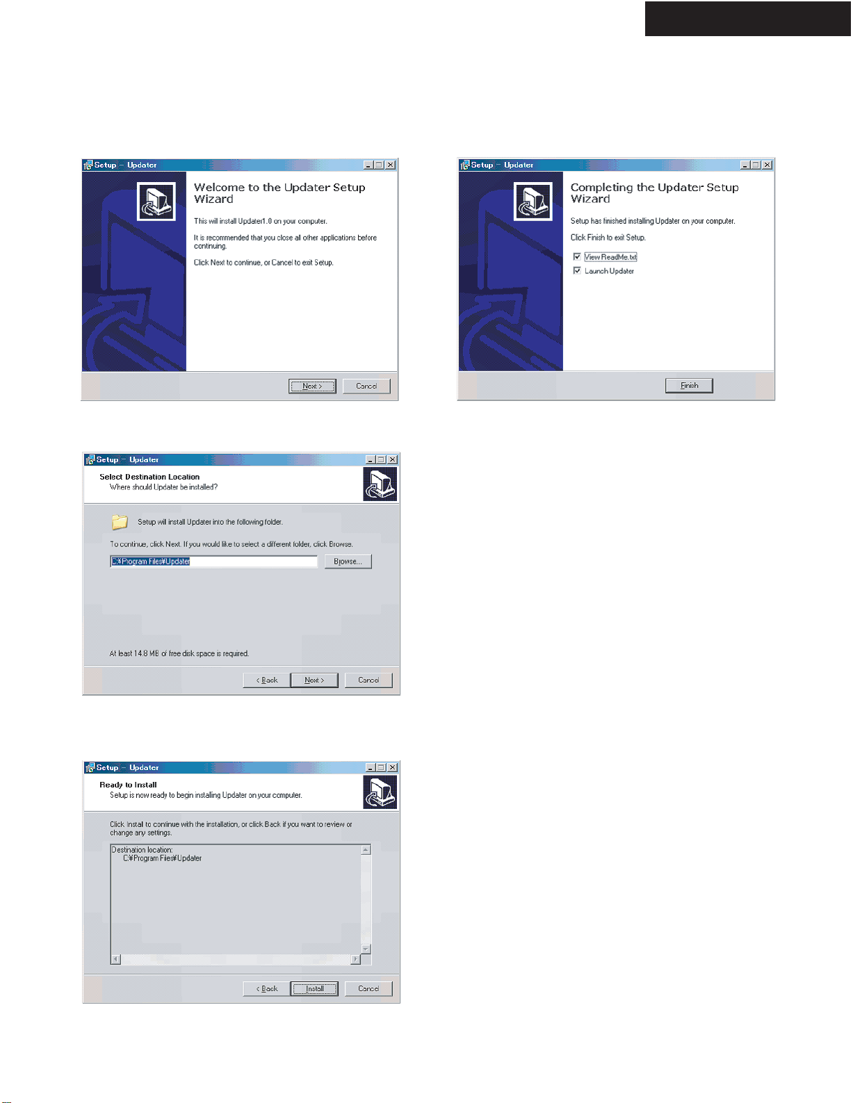
 User manual")