manuals.online logo
Brands
  1. Home
  2. •
  3. Brands
  4. •
  5. Onkyo
  6. •
  7. Stereo Receiver
  8. •
  9. Onkyo TX-NR801E User manual

Onkyo TX-NR801E User manual

Other manuals for TX-NR801E

1

This manual suits for next models

1

Other Onkyo Stereo Receiver manuals

Onkyo TX-SR804 User manual

Onkyo

Onkyo TX-SR804 User manual

Onkyo 8555 - TX AV Receiver User manual

Onkyo

Onkyo 8555 - TX AV Receiver User manual

Onkyo TX-8522 User manual

Onkyo

Onkyo TX-8522 User manual

Onkyo TX-3000 User manual

Onkyo

Onkyo TX-3000 User manual

Onkyo TX-NR3007B User manual

Onkyo

Onkyo TX-NR3007B User manual

Onkyo TX-8522 User manual

Onkyo

Onkyo TX-8522 User manual

Onkyo TX-NR595 User manual

Onkyo

Onkyo TX-NR595 User manual

Onkyo TX-NR828(B) User manual

Onkyo

Onkyo TX-NR828(B) User manual

Onkyo TX-5000 User manual

Onkyo

Onkyo TX-5000 User manual

Onkyo TX-8050 User manual

Onkyo

Onkyo TX-8050 User manual

Onkyo TX-SR308 User manual

Onkyo

Onkyo TX-SR308 User manual

Onkyo TX-L20D User manual

Onkyo

Onkyo TX-L20D User manual

Onkyo TX-SR501 User manual

Onkyo

Onkyo TX-SR501 User manual

Onkyo TX-NR1000E User manual

Onkyo

Onkyo TX-NR1000E User manual

Onkyo TX-8522 User manual

Onkyo

Onkyo TX-8522 User manual

Onkyo TX-5000 User manual

Onkyo

Onkyo TX-5000 User manual

Onkyo TX-RZ1100-B Installation guide

Onkyo

Onkyo TX-RZ1100-B Installation guide

Onkyo TX-SR3100 User manual

Onkyo

Onkyo TX-SR3100 User manual

Onkyo TX-NR696-S User manual

Onkyo

Onkyo TX-NR696-S User manual

Onkyo TX-NR595 Manual

Onkyo

Onkyo TX-NR595 Manual

Onkyo TX SR875 - AV Receiver Use and care manual

Onkyo

Onkyo TX SR875 - AV Receiver Use and care manual

Onkyo TX-RZ620 Installation guide

Onkyo

Onkyo TX-RZ620 Installation guide

Onkyo TX-RZ820 User manual

Onkyo

Onkyo TX-RZ820 User manual

Onkyo TX-8011 User manual

Onkyo

Onkyo TX-8011 User manual

Popular Stereo Receiver manuals by other brands

Teac AG-680 Service manual

Teac

Teac AG-680 Service manual

Kenwood KR-V888D instruction manual

Kenwood

Kenwood KR-V888D instruction manual

Teac AGV1050 owner's manual

Teac

Teac AGV1050 owner's manual

Sony STR-435 operating instructions

Sony

Sony STR-435 operating instructions

Pioneer Elite SC-68 Service manual

Pioneer

Pioneer Elite SC-68 Service manual

Pioneer SX-1250 operating instructions

Pioneer

Pioneer SX-1250 operating instructions

Marantz CINEMA 70S owner's manual

Marantz

Marantz CINEMA 70S owner's manual

Kenwood KMDX92 instruction manual

Kenwood

Kenwood KMDX92 instruction manual

Yamaha RX-830 owner's manual

Yamaha

Yamaha RX-830 owner's manual

Pioneer AVH-Z7250BT owner's manual

Pioneer

Pioneer AVH-Z7250BT owner's manual

Denon AVR-1311 owner's manual

Denon

Denon AVR-1311 owner's manual

Denon AVR-S760H owner's manual

Denon

Denon AVR-S760H owner's manual

Denon AVR-X7200W Service manual

Denon

Denon AVR-X7200W Service manual

Sony XAV-1500 operating instructions

Sony

Sony XAV-1500 operating instructions

Radio Shack DX-399 owner's manual

Radio Shack

Radio Shack DX-399 owner's manual

Sony STR-DE535 - Fm Stereo/fm-am Receiver operating instructions

Sony

Sony STR-DE535 - Fm Stereo/fm-am Receiver operating instructions

Pioneer SX-1000TA operating instructions

Pioneer

Pioneer SX-1000TA operating instructions

Yamaha MusicCast TSR-5B3D owner's manual

Yamaha

Yamaha MusicCast TSR-5B3D owner's manual

manuals.online logo
manuals.online logoBrands
  • About & Mission
  • Contact us
  • Privacy Policy
  • Terms and Conditions

Copyright 2025 Manuals.Online. All Rights Reserved.

TX-NR801/E
SERVICE MANUAL
SERVICE MANUAL
AV RECEIVER
MODEL TX-NR801/E
Ref. No. 3785
102003
Black, Golden and Silver models
BMDD,BMDC 120V, AC 60Hz
GMWT,GMWR 120/220~230V, AC 50/60Hz
BMPP, SMPP,BMPA,GMPA 230~240V, AC 50Hz
GMGK 220V, AC 50Hz
DSP A-FO
RM LISTENING MODE MEMORY
THX
SURROUNDDIRECT
/
PURE AUDIO STEREO
FM
MODE
MEMORY
ENTER
RE
TURN
SETUP
TUNING
PRESET
SAFETY-RELATED COMPONENT
WARNING!!
COMPONENTS IDENTIFIED BY MARK ON THE
SCHEMATIC DIAGRAM AND IN THE PARTS LIST ARE
CRITICAL FOR RISK OF FIRE AND ELECTRIC SHOCK.
REPLACE THESE COMPONENTS WITH ONKYO
PARTS WHOSE PART NUMBERS APPEAR AS SHOWN
IN THIS MANUAL.
MAKE LEAKAGE-CURRENT OR RESISTANCE
MEASUREMENTS TO DETERMINE THAT EXPOSED
PARTS ARE ACCEPTABLY INSULATED FROM THE
SUPPLY CIRCUIT BEFORE RETURNING THE
APPLIANCE TO THE CUSTOMER.
1
TX-NR801/E
SPECIFICATIONS
AMPLIFIER SECTION TUNER SECTION
FM
AM
GENERAL
Specifications and features are subject to change without
notice.
Continuous average power output (FTC) (USA and Canadian mod-
els):
All channels: 100 W per channel min. RMS
into 8 , 2 channels driven from
20 Hz to 20 kHz with no more
than 0.08% total harmonic dis-
tortion.
130 W min. RMS into 6 ,
2 channels dri ven, 1 kHz with no
more than 0.1% total harmonic
distortion.
Continuous power output (DIN)
(European model): 135 W at 6
Maximum power output (EIAJ)
(Asian model): 160 W at 6
Dynamic power output (stereo) 2 250 W at 3
2 210 W at 4
2 130 W at 8
Total Harmonic Distortion: 0.08% at rated power
0.08% at 1 W output
IM Distortion: 0.08% at rated power
0.08% at 1 W output
Damping factor: 60 at 8
Input sensitivity and impedance
PHONO: 2.5 mV , 50 k
LINE (CD, TAPE, DVD,
VIDEO 1-5): 200 mV , 50 k
MULTICHANNEL INPUT
(FRONT L/C/R, SUR-
ROUND L/R, SURROUND
BACK L/R): 200 mV , 50 k
(SUBWOOFER): 36 mV, 50 k
COAXIAL 1, 2, 3 (DIGI-
TAL): 0.5 Vp-p, 75
DVD, VIDEO 1, 2, 3, 4, 5: 1 Vp-p, 75 (Composite Video)
1 Vp-p, 75 (S-V ideo, Y signal)
0.28 Vp-p, 75 (S-V ideo, C sig-
nal)
COMPONENT VIDEO 1, 2: 1 Vp-p, 75 (Y)
0.7 Vp-p, 75 (PB/CB, PR/CR)
Output level and impedance
Rec out (TAPE, VIDEO 1,2): 200 mV , 470
Pre out: 1 V, 470
ZONE 2 OUT : 100 mV , 470
VIDEO (VIDEO 1, 2, MONI-
TOR OUT , ZONE 2 OUT): 1 Vp-p, 75 (Composite Video)
S-VIDEO (VIDEO 1, 2,
MONIT OR OUT): 1 Vp-p, 75 (S-V ideo, Y signal)
0.28 Vp-p, 75 (S-V ideo, C sig-
nal)
COMPONENTVIDEO OUT : 1 Vp-p, 75 (Y)
0.7 Vp-p, 75 (PB/CB, PR/CR)
Phono overload: 120 mV RMS at 1 kHz, 0.5%
T.H.D.
Frequency response: 10 Hz to 100 kHz: +1/-3 dB (CD
in Direct mode)
RIAA deviation: 20 Hz to 20 kHz: ±0.8dB
Tone Control
Bass: ±10 dB at 50 Hz
Treble: ±10 dB at 20,000 Hz
Signal-to-noise ratio (direct)
PHONO:
Line: 80 dB (IHF A, 5 mV input)
110 dB (IHF A, 0.5 V input)
Ethernet port: 100BASE-TX
Supported audio file format: MP3, WMA, WAV (non-compres-
sion, sampling rates of 32 kHz,
44.1 kHz, and 48 kHz supported)
Tuning range
USA & Canadian models: 87.50~108.00 MHz (100 kHz
steps)
Other models: 87.50~108.00 MHz (50 kHz steps)
Usable sensitivity
Mono: 11.2 dBf, 1.0 µV (75 , IHF)
0.9 µV (75 , DIN)
Stereo: 17.2 dBf, 2.0 µV (75 , IHF)
23 µV (75 DIN)
50 dB quieting sensitivity
Mono: 17.2 dBf, 2.0 µV (75 )
Stereo: 37.2 dBf, 20.0 µV (75 )
Capture ratio: 2.0 dB
Image rejection ratio
USA & Canadian models: 40 dB
Other models: 85 dB
IF rejection ratio: 90 dB
Signal-to-noise ratio
Mono: 76dB
Stereo: 70dB
Alternate channel attenuation:Mono 55 dB
Selectivity: 50dB(DIN)
AM suppression ratio: 50 dB
Total harmonic distortion
Mono:
Stereo:
Frequency response: 30 Hz~15 kHz, ±1.0 dB
Stereo separation: 45 dB at 1 kHz
30 dB at 100 Hz~10 kHz
Tuning range
USA & Canadian models: 530~1,710 kHz (10 kHz steps)
Other than worldwide models:522~1,611 kHz(9kHzsteps)
Worldwide models: 522~1,611 kHz (9 kHz steps), or
530~1,710 kHz (10 kHz steps)
Usable sensitivity: 30 µV
Image rejection ratio: 40 dB
IF rejection ratio: 40 dB
Signal-to-noise ratio: 40 dB
Total harmonic distortion: 0.7%
Power supply
USA & Canadian models: AC 120V, 60 Hz
European & Australian mod-
els: AC 230-240V, 50 Hz
Some Asian models: AC 220-230V, 50/60 Hz
Worldwide models: AC 220-230V and 120V switch-
able, 50/60 Hz
Power consumption
USA & Canadian models: 8.1A
Other models: 655W
Dimensions (W H D): 435 175 459 mm
17-1/8" 6-7/8" 18-1/16"
Weight
USA & Canadian models: 16.8 kg (37.1 lbs)
Other models: 17.8 kg (39.3 lbs)
0.2%
0.3%
2
TX-NR801/E
SERVICE PROCEDURES
1. Replacing the fuses
This symbol located near the fuses indicates
that the fuse used is fast operating type. For continued
protection against fire hazard, replace with same type fuse.
For fuse rating refer to the marking adjacent to the symbol.
Ce symbole indique que le fusible utlise est a
rapide.Pour une protection permanente, n'untiliser que
fusibles de meme type. Ce darnier est la qu le present
symbol est appse.
Note: <D>: 120V model only
<O>: Except 120V model
<T>: Worldwide model only
<R>: Chinese model only
CIRCUIT NO. PART NO. DESCRIPTION
F901 252199 10A-UL,Fuse <D/T/R>
F902 252077, 4A-SE-EAK,
252243 or 4A-SE-TL250V or
252277 4A-SE-TL250V <O>
F903 252164 or 5A-UL/T-237 or
252258 5A-T/UL-ST2,Fuse <D>
252075, 2.5A-SE-EAK,
252241 or 2.5A-SE-TL250V or
252275 2.5A-SE-TL250V,Fuse <O>
F9501,F9502 252160 or 2.5A-UL/T-237 or
252254 2.5A-T/UL-ST2,Fuse <D>
252075, 2.5A-SE-EAK,
252241 or 2.5A-SE-TL250V or
252275 2.5A-SE-TL250V,Fuse <O>
F9503,F9504 252158 or 1.6A-UL/T-237 or
252252 1.6A-T/UL-ST2,Fuse <D>
252073, 1.6A-SE-EAK,
252239 or 1.6A-SE-TL250V or
252273 1.6A-SE-TL250V,Fuse <O>
2.To initialize the unit
This device employs a microprocessor to perform various
functions and operations.If interference generated by an
external power supply, radio wave, or other electrical source
results in accident which causes the specified operations
and functions to operate abnormally.
To perform a result, please follow the procedure below.
1.Press the STANDBY ON button to turn on the unit.
2.Press and hold down the VIDEO 1 button, then press the
STANDBY/ON button.
3.After "CLEAR" is displayed, the preset memory and each
mode stored in the memory, such as surround, are
initialized and will return to the factory setting.
4.Unplug the power supply cord.
4. Memory Preservation
This unit does not require memory preservation batteries.A
built-in memory power back-up system preserves the contents
of the memory during power failures and even when the unit is
unplugged.The unit must be plugged in order to charge the
back-up system.
The memory preservation period after the unit has been
unplugged varies depending on climate and placement of the
unit. On the average, memory contents are protected over a
period of a few weeks after the last time the unit has been
unplugged.This period is shorter when the unit is exposed to a
highly humid climate.
5.Setting the voltage selector
(Worldwide models only)
Worldwide models are equipped with a voltage selector so
that you
supplies. Be
can set your TX-NR801 to conform with local power
sure to set this switch to match the voltage of
your area before plugging in the unit.
Determine the proper voltage for your area: 220-230 V or
the preset voltage is not correct for your area,
into the groove in the switch and slide
(220-230 V), whichever is appropriate.
the power supply in
120 V. If
insert a screwdriver
the switch all the way to the top (120 V) or bottom
3. Safety-check out
(U.S.A. model only)
After correcting the original service problem, perform the
following safety check before releasing the set to the customer.
Leakage Current Check
Measure leakage current to a known earth ground(water pipe,
conduit, etc.) by connecting a leakage current tester between
the earth ground and exposed metal parts of the appliance
(input/output terminals, screwheads,metal overlays, etc.).
Plug the power supply cord directly into a 120V AC 60 Hz outlet
and turn Standby switch on.Any current meausred must not
exceed 0.5mA.
SURR
BACK/
ZONE 2
SPEAKERS
AUDIO VIDEO S VIDEO
MONITOR
OUT
RL
IN
IN
IN
IN
IN
ZONE 2
DVD
VIDEO 1
VIDEO 2
VIDEO 3
VIDEO 4
AUDIO VIDEO S VIDEO
COMPONENT
VIDEO
Y
PB
PR
OUTPUT
INPUT 1
Y
PB
PR
INPUT 2
Y
PB
PR
FRONT SPEAKERS L
RL R
SURR SPEAKERS
CENTER
SPEAKER
RL
RL
OUT
OUT
OUT
I
R
IN
OUT
REMOTE
CONTROL
PHONO
DIGITAL
IN
PRE OUT
DIGITAL
OUT
OPT
OPT
2
1
2
1
2
3
FRONT
SUB
SURR
RL
AUDIO
RL
CD
TAPE
RL
AUDIO
1
3
GND
SURR
BACK/
ZONE 2
IN
OUT
COAX
RL
MULTI
CH
INPUT
FRONT
SUB
SURR
SURR
BACK
CENTER
RL
RL
AM
FM
75
CENTER
ANTENNA
IN
IN
(
Net-Tune
)
ETHERNET
4 OHMS MIN. OR
6 OHMS MIN.
/SPEAKER
CAUTION:
SPEAKER
IMPEDANCE
SEE INSTRUCTION
MANUAL FOR
CORRECT SETTINGS.
AV RECEIVER
MODEL NO. TX-NR
801
VOLTAGE
SELECTOR
220-230V
120V
AC
OUTLETS
AC 230-240
V 50
Hz
SWITCHED
TOTAL100
W MAX.
120V
VOLTAGE
SELECTOR
220-230V
6.AM Frequency Step Sub-menu
orldwide model Only)
This sub-menu only appears on the worldwide model.
The setting in this sub-menu determines the incremental
or decremental amount when adjusting the AM tuner
frequency. The initial setting is 9 kHz, and this needs
only to be changed if you are using the TX-NR801/
TX-NR801E in a 10 kHz region.
a. Frequency Step
9 kHz: Select when you use the TX-NR801/
TX-NR801E in North America.
10 kHz: Select when you use the TX-NR801/
TX-NR801E in other than USA and Canada.
0-5.AM Frequency Step
a.Frequency Step
:9 kHz
Quit:[SETUP]
3
TX-NR801/E
FRONT PANELVIEW
Toselect an input source, press the desired button
(REC OUT or ZONE 2) and then press one of the
input source button within 8 seconds.That source will
be output for recording or viewing in the remote zone.
To set the output to the source channel, press the
desired button (REC OUT or ZONE 2) twice in suc-
cession.Toturn of f the output, press the desired but-
ton (REC OUT or ZONE 2) and then press the OFF
button within 8 seconds.
Note:
The Rec Out and Zone 2 buttons use the same cir-
cuit and therefore cannot be used at the same time.
When REC OUT is selected, nothing is output to
Zone 2.When ZONE 2 is selected, REC OUT is
automatically fixed to SOURCE.
SETUP button
Press to enter the Setup Menu. The OSD Menu will
appear on the TV monitor as well as the front dis-
play on the TX-NR801/TX-NR801E.
ENTER button
Press to display the screen for the item that is
selected in the Setup Menu.
RETURN button
In the Setup Menu, press to go back one level. If
pressed while at the Main Menu, you will exit the
Setup Menu.
MASTER VOLUME dial
Use to control the volume in the main zone. The vol-
ume for the remote zone (Zone 2) is independent.
VIDEO 5 INPUT terminals
For connecting a video camera or game device.
Input source buttons and indicators (DVD,
VIDEO 1~5,TAPE,TUNER, PHONO, CD, and
NET AUDIO)
Press these buttons to select the input source for the
main zone.
Toselect the input source for the remote zone (Zone
2) or recording out (REC OUT), first press the
ZONE 2 or REC OUT button, and then press the
desired input source button.The input channel with
its indicator lit red is output to REC OUT and the
one with its indicator lit green is output to ZONE 2.
UPSAMPLING indicator
Lights during upsampling.This function is available
when the input source is Analog/PCM and the lis-
tening mode is set to the stereo or surround mode.
PHONES jack
This is a standard stereo jack for connecting stereo
headphones.
PURE AUDIO indicator
Lights during pure audio playback.
AInput signal path indicators
Shows from which terminal the input signal is com-
ing.
BListening mode or digital input format
indicators
One of these indicators lights to show the format of
the current input source. In addition, one of the lis-
tening mode indicators lights to indicate the current
listening mode.
CTuning indicators
AUTO indicator
Lights when receiving FM broadcasts in the stereo
mode.Turns off when placed into the monaural
mode.
RDS indicator (European models only)
Lights when an RDS station is being received.
TUNED indicator
Lights when a radio station is being received.
FM STEREO indicator
Lights when an FM broadcast station is being
received in stereo.Turns off when placed into the
monaural mode.
DMulti function display
During normal operation, shows the current input
source and volume. When the FM or AM input is
selected, shows the frequenc y and preset number.
When the DISPLAY button is pressed, shows the
listening mode and input source format. However,
does not show the source format when the FM or
AM source is selected.
EVolume display
Shows the volume level.
FSLEEP indicator
Lights when the sleep timer is turned on.
Front Panel Display
4
TX-NR801/E
FRONT PANELVIEW
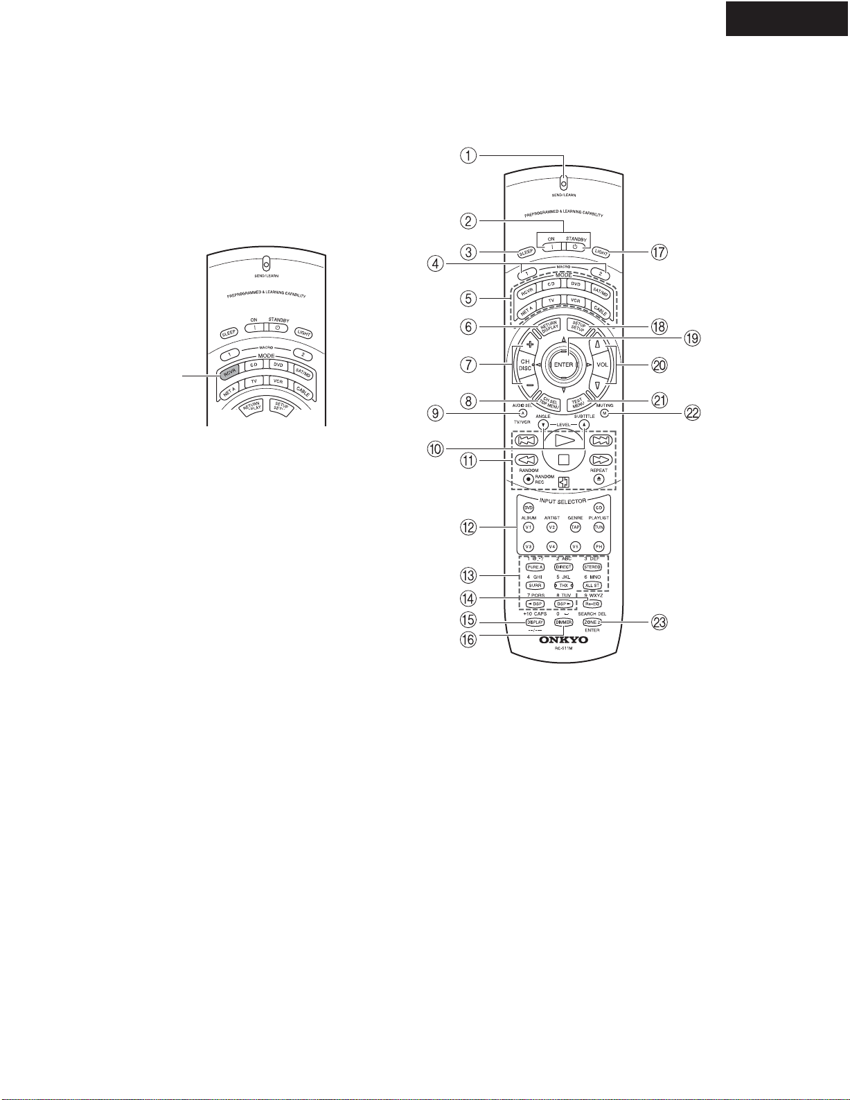
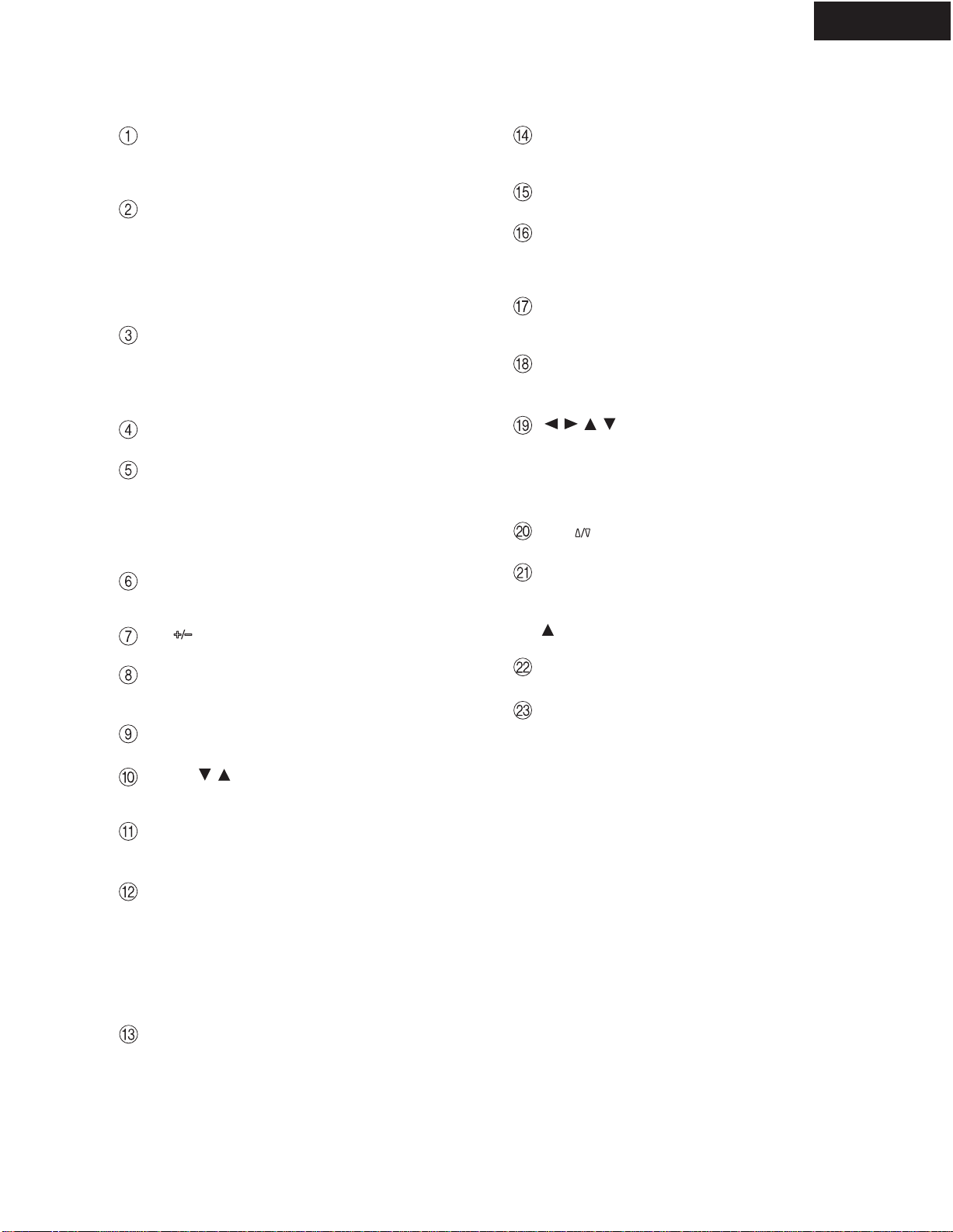
POWER switch (for all models other than
USA, Canadian and Australian models)
Press to turn on and off the main power supply for
the TX-NR801/TX-NR801E. When the TX-NR801/
TX-NR801E is turned on with the POWER switch,
the STANDBY indicator lights.
* Before turning on the power, check to make sure
that all cords are properly connected.
* When the power is turned on, a sudden surge of cur-
rent will occur that may adversely affect the opera-
tion of other devices.To prevent this, do not plug the
TX-NR801/TX-NR801E into the same circuit used
by sensitive equipment, e.g., computers.
STANDBY/ON button
If pressed with the POWER switch turned on (with
the receiver plugged in for USA, Canadian and Aus-
tralian models), the TX-NR801/TX-NR801E turns
on and the display lights up. If pressed again, the
TX-NR801/TX-NR801E returns to the standby state.
In the standby state, the display is turned off and the
TX-NR801/TX-NR801E cannot be operated.
STANDBY indicator
Lights when the TX-NR801/TX-NR801E is in the
standby state and when a signal is received from the
remote controller..
AUDIO SELECTOR button
Press to select the type of audio input signal.
DIRECT/PURE AUDIO button
Press to switch between the direct and pure audio
listening modes.
Remote control sensor
DISPLAY button
Press to display information about the current input
source signal. Each time you press the DISPLAY
button, the screen changes to show you different
information concerning the input signal.
DIMMER button (Other than European
models)
Press to set the brightness of the front display.. There are
three settings available: normal, dark, and very dark.
The brightness of the front display can also be
changed using the remote controller.
RT/PTY/TP button (European models only)
This button is only available on European models.
Press this button to tune into the Radio Data System
(RDS) for FM broadcasting. RDS was developed
within the European Broadcasting Union (EBU)
and is available in most European countries. Each
time the button is pressed, the display changes from
RT(radio text) to PTY (program type) to TP (traffic
program) and then back to RT again.
STEREO button
Selects for the stereo listening mode.
SURROUND button
Selects for the Dolby Pro Logic II, DTS Neo:6,
Dolby Digital, or DTS listening modes.
THX button
Selects for the THX listening mode.
DSP / buttons
Switches to the DSP (Digital Signal Processing) modes.
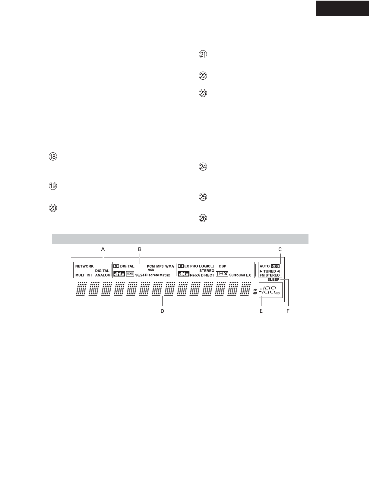
Front display
MEMORY button
Press to assign the radio station to which you are
currently tuned to a preset channel or press to delete
a previously preset station.
FM MODE button
Press to change the stereo mode from AUTO to
MONO and vice versa. Each time this button is
pressed, the AUTO indication turns on and off indicat-
ing the current mode. If you are listening to an FM
radio station in stereo and the sound cuts out or there is
a great deal of noise, switch from AUTO to MONO.
TUNING / , PRESET / buttons
To tune into a radio station, press the TUNING /
buttons.The tuner frequency is displayed in the
front display and it can be changed in 100-kHz (or
50-kHz) increments for FM and 10-kHz (or 9-kHz)
increments for AM.
When FM is selected as the input source, you can hold
down either the TUNING or button and then
release it to activate the auto-search feature. It will
search for a station in the direction of the button you
pressed and stop when it tunes into one.When navigat-
ing through the menu settings, these buttons move the
cursor up or down (or change the highlighted item).
To select a radio station that was stored using the
MEMORY button, press the PRESET / buttons.
When navigating through the menu settings, these
buttons select the value or item that you selected
with theTUNING / buttons.
When you press the SETUP button, the TUNING
and PRESET buttons become cursor buttons to be
used for Setup Menu operations.
REC OUT/ZONE 2/OFF buttons
These buttons allow you to use the TX-NR801/
TX-NR801E to output to a remote zone (Zone 2) or
to another component for recording (Rec Out).Press
the REC OUT button to output the audio and video
signals to a recording component for recording. Press
the ZONE 2 button to enjoy the output from the
TX-NR801/TX-NR801E in a different room, which is
referred to as the remote zone (Zone 2).
When either button is pressed, the currently selected
input source for recording or outputting to the remote
zone is displayed in the front panel display. If
"SOURCE" is displayed, then the same input source
as that selected for the main zone will be output.
5
TX-NR801/E
FRONT PANELVIEW
Here is an explanation of the controls and displays on the front panel of the TX-NR801/TX-NR801E.
The specifications for your model may differ due to regional requirements.
Front Panels
DSP A-FO
RM LISTENING MODE MEMORY
THX
SURROUNDDIRECT
/
PURE AUDIO STEREO
FM
MODE
MEMORY
ENTER
RE
TURN
SETUP
TUNING
PRESET
USA, Canadian and Australian models
DSP A-FO
RM LISTENING MODE MEMORY
THX
SURROUNDDIRECT
/
PURE AUDIO STEREO
FM
MODE
MEMORY
ENTER
RE
TURN
SETUP
TUNING
PRESET
Other models
6
TX-NR801/E
REAR PANELVIEW
DIGITAL IN/OUT
These jacks are for connecting components with
digital input and output capabilities.
PRE OUT
To use the TX-NR801/TX-NR801E as a preampli-
fier, connect a power amplifier to this jack.
ANTENNA
These jacks are for connecting the FM indoor
antenna and the AM loop antenna that are supplied
with the TX-NR801/TX-NR801E.
ZONE 2VIDEO OUT
This jack is for connecting the component that will
be used in the remote zone (Zone 2).
MONITOR OUT VIDEO/SVIDEO
These jacks are for connecting to the video input
jacks on television monitors or projectors.
COMPONENTVIDEO OUTPUT
These jacks are for connecting to the component
video input jacks on television monitors or projectors.
ETHERNET (Net-Tune)
This connector is for connecting to an Ethernet network.
SPEAKERS
These terminals are for connecting the speakers.
AC OUTLETS
ThisACoutlet is provided to plug in the power cord
from another component.The shape and number of
the AC outlet depend on the shipping destination.
MULTI CH INPUT
This connector is for connecting components with a
multichannel output.
PHONO/CD/TAPE AUDIO IN/OUT
These connectors are for connecting to the audio
input and output jacks on audio components.
DVD/VIDEO1-4 IN/OUT
These connectors are for connecting to the video
input and output jacks on video components.
COMPONENTVIDEO INPUT1/2
These connectors are for connecting to the compo-
nent video outputs of video components that have
them.
IR IN/OUT
These connectors are for connecting the remote sen-
sor of a multi-room kit (sold separately).
This jack is for connecting other Onkyo compo-
nents equipped with the same terminal.The
audio connection cables must also be connected.
VOLTAGE SELECTOR (Worldwide models
only)
This is only av ailable on the worldwide model.
Before connecting the power cord to the wall outlet,
be sure to set this to the correct power supply volt-
age for your region.
SURR
BACK/
ZONE 2
SPEAKERS
AUDIO VIDEO S VIDEO
MONITOR
OUT
RL
IN
IN
IN
IN
IN
ZONE 2
DVD
VIDEO 1
VIDEO 2
VIDEO 3
VIDEO 4
AUDIO VIDEO S VIDEO
COMPONENT
VIDEO
Y
PB
PR
OUTPUT
INPUT 1
Y
PB
PR
INPUT 2
Y
PB
PR
FRONT SPEAKERS L
RL R
SURR SPEAKERS
CENTER
SPEAKER
RL
RL
OUT
OUT
OUT
I
R
IN
OUT
REMOTE
CONTROL
PHONO
DIGITAL
IN
PRE OUT
DIGITAL
OUT
OPT
OPT
2
1
2
1
2
3
FRONT
SUB
SURR
RL
AUDIO
RL
CD
TAPE
RL
AUDIO
1
3
GND
SURR
BACK/
ZONE 2
IN
OUT
COAX
RL
MULTI
CH
INPUT
FRONT
SUB
SURR
SURR
BACK
CENTER
RL
RL
AM
FM
75
CENTER
ANTENNA
IN
IN
(
Net-Tune
)
ETHERNET
4 OHMS MIN. OR
6 OHMS MIN.
/SPEAKER
CAUTION:
SPEAKER
IMPEDANCE
SEE INSTRUCTION
MANUAL FOR
CORRECT SETTINGS.
AC OUTLETS
AC
120
V 60
Hz
SWITCHED
TOTAL 120W 1A MAX.
AV RECEIVER
MODEL NO. TX-NR
801
VOLTAGE
SELECTOR
220-230V
120V
7
TX-NR801/E
REMOTE CONTROLLER
The RC-511M is a multi-functional remote controller.
The instructions given here only explain how to use the
remote controller in conjunction with the TX-NR801/
TX-NR801E. To operate the TX-NR801/TX-NR801E
using the remote controller, First press the RCVR but-
ton in the MODE area to place the remote controller in
the receiver mode.
RCVR
button
8
TX-NR801/E
REMOTE CONTROLLER
SEND/LEARN indicator
Lights red when signals are sent by the remote con-
troller. It also flashes when a button is pressed and
the battery power is low.
ON/STANDBY button
ON: Press to turn on the TX-NR801/TX-NR801E.
STANDBY: Press to place the TX-NR801/
TX-NR801E in the standby state.
Be aware that pressing the STANDBY button only
places the TX-NR801/TX-NR801E in standby and
does not turn the power off completely.
SLEEP button
Press to set the sleep function.
The SLEEP button enables you to set the
TX-NR801/TX-NR801E to turn off automatically
after a specified time period.
MACRO 1, 2 button
Press to program or execute the macro function.
MODE buttons and indicators
Press to select the component to be operated by the
remote controller.When a MODE button is pressed,
it will light for 8 seconds. The selected MODE but-
ton will also light whenever any other operation but-
ton is pressed.
RETURN button
Press to enter the selected setting and return to the
previous menu.
CH button
Press to select a preset channel for the tuner.
CH SEL button
Press to select a speaker channel when adjusting the
speaker level.
AUDIO SEL button
Press to select the audio input signal.
LEVEL / buttons
Press to adjust the volume of the speaker selected
using the CH SEL button.
Operation buttons
Press to operate other devices connected to the
TX-NR801/TX-NR801E.
INPUT SELECTOR buttons
Press to select an input source.
Same as the input selector buttons on the front panel
of the TX-NR801/TX-NR801E.The input source
for each button is given here. DVD:DVD, CD:CD,
V1:VIDEO1, V2:VIDEO2, V3:VIDEO3,
V4:VIDEO4,V5:VIDEO5, TAP:TAPE, TUN:FM/
AM, PH:PHONO.
Listening mode buttons
Press to select a listening mode.
Re-EQ button
Depending on the listening mode, you can turn the
Re-EQ function on or of f.
DISPLAY button
For changing the front display.
DIMMER button
Adjusts the display brightness.
There are three settings available: normal, dark, and
very dark.
LIGHT button
Press to turn on and off the lights in the buttons of
the remote controller.
SETUP button
Press to display the Setup Menu on theTV screen
and in the display. Press again to exit the menu.
///,ENTER button
When in the Setup Menu, press the upper and lower
arrow buttons to select an item, press the right and
left arrow buttons to select parameter values or
modes, and press the ENTER button to advance to
the next item.
VOL button
Press to adjust the volume.
TEST button
This button is used to set the speaker output levels.
Use this button in conjunction with the LEVEL
and CH SEL buttons to calibrate the speaker lev-
els without entering the Setup Menu.
MUTING button
Press to activate the mute function.
ZONE 2 button
Press to perform operations in the remote zone.
9
TX-NR801
EXPLODEDVIEW (120V and Australian models)
TX-NR801
78
17
60
78
17
60
71
46
90
84
61
67
100
88
T901
77
U28
674
74
F6901
F6902
U36
74
74
61
74
U33
74
F903
U27
U45
F901
F902
68 U22
U37
U26
74
74
39
U44
U43
U42
U46
80
80 9
85 94
80 64
P901
69
74
U41
U13U12
47
U11
U7
P7201
81
14
71
44
45
7
48
45
16
99
4
32
80
53
55
33
12
U3
U6
56
U5
30
74
U15
U1 U14
U4
2
61
87
96
33
10
1
75
81
15
15
P2901 U2
13
11
23
U30 86 U8
U31 P602
P603C
U47
D
59
92
U48
70
74
74
A
80
AD
74
P1010
U61
19
20
91
91
95
57 103
58
74
74
F9501
F9502
F9504
F9503
U23
74
Q6056
Q6066
U32 P7701
Q6062
99
U21
69 74
74
39
U24
U36
68
74
649
82 82
F9501A
Q6052
Q9422B
Q9422A
74
5
10