Working: 8% - 80%,
Storage: 5% - 95%.
Dustiness of air: no more than 75 mcg / m3.
Since particulate matter and / or contaminated media can damage the sensor
or affect measurements, we recommend using a filter (20-50 microns) in front of the
flow sensor!
The applied flow sensor withstands the temperature of the measured liquid up
to 90C. Do not allow the temperature to rise above this value! If there is a need for
continuous operation, then a cooling radiator must be installed in front of the
flowmeter!
If the device was transferred from a cold to a warm room, you need to give
time for 1-1.5 hours to the device to warm up to ambient temperature.
After switching on, let the device run for 2-5 minutes, then proceed to work.
6. Limitations of liability
The manufacturer is not liable to the buyer of this product or a third party for
damage or loss suffered by customers or a third party as a result of improper use of
the product, including inept or erroneous actions of personnel, as well as for losses
caused by the action or inaction of this device.
Under no circumstances will the manufacturer be liable for lost profits, lost
savings, losses caused by an accident, or other subsequent economic losses, even if
the company was notified of the possibility of such losses. The manufacturer is not
liable for losses incurred by you on the basis of claims of a third party, or caused by
failure to fulfill your obligations.
The manufacturer is not responsible for any malfunctions and losses resulting
from the use of additional devices not recommended for use with this device, as well
as its modification, repair or modification to its design, not provided for by the
operating instructions.
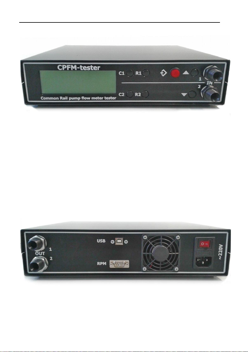
7. Preparation for work
Before using the CPFM-Tester, carefully read the operating instructions.
The flowmeter is connected using 3/8 ”pipe transitions to the hose.
When preparing the device for operation, it is necessary to carry out the
following actions: conduct an external inspection of the device, check the reliability
of pipe connections.
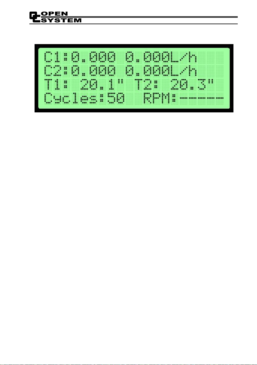
8. Operating of the device
8.1. Display.
In the initial state, the following information is displayed (see left to right, top
to bottom):