3
Subject to change without notice
Accessories supplied: Line Cord, Operators Manual, 2 Probes1:1/ 10:1
Screen photo of stored sinewave signals. Screen shot of measurement software.
The worldwide success of HAMEG´s HM205 and HM305 has led to the
introduction of the new microprocessor controlled HM407 Analog/Digital
oscilloscope. This instrument offers much more performance and specifications
over its predecessores. The HM407incorporates a microprocessor-basedsystem
that extensively automates operation. The majority of signals can be displayed by
simply pressing the “Autoset“ button. A “Save/Recall“ function is available for
storing frequently used setup parameters.
The increased maximum sampling rate of 100MS/s now allows to capture a
10MHzsignal in “Single“ mode with 10 samples(dots) per period. The automatic
Dot-Join function provides linear connections between the captured points,
ensuring that all digitized signals are displayed without gaps. New features are the
two reference memories, allowing their contents to be compared with the live
signal at any time. Cursors can be activated for waveform measurements. All
important parameter settings are displayed on the CRT screen. The built-in RS232-
Interface enables remote control operation and signal processing via a PC.
Unique in its price range is also the analog section of the HM407. The increased
bandwidth of 40MHz (-3dB) allows the stable display of signals up to 100MHz. As
always, the Component Tester with one-button control is a standard feature in
the HM407. This is also true for the switchable 1kHz/1MHz Calibrator which
permits you to check the transient characteristics from probe tip to the screen at
any time.
All in all, the new HM407 presents itself as a practical hands-on oscilloscope for
today’s progressive measurement requirements offering a price/performance ra-
tio that sets new standards world-wide.
Specifications
Vertical Deflection
Operating modes: Channel I or CH II separate,
Channel I and II: alternate or chopped
(Chopper Frequency approx. 0.5MHz)
Sum or Difference from Channel I and ± Ch. II,
XY-Mode: via CH I (X) and CH II (Y).
Frequency range: 2x DC to 40MHz (−3dB).
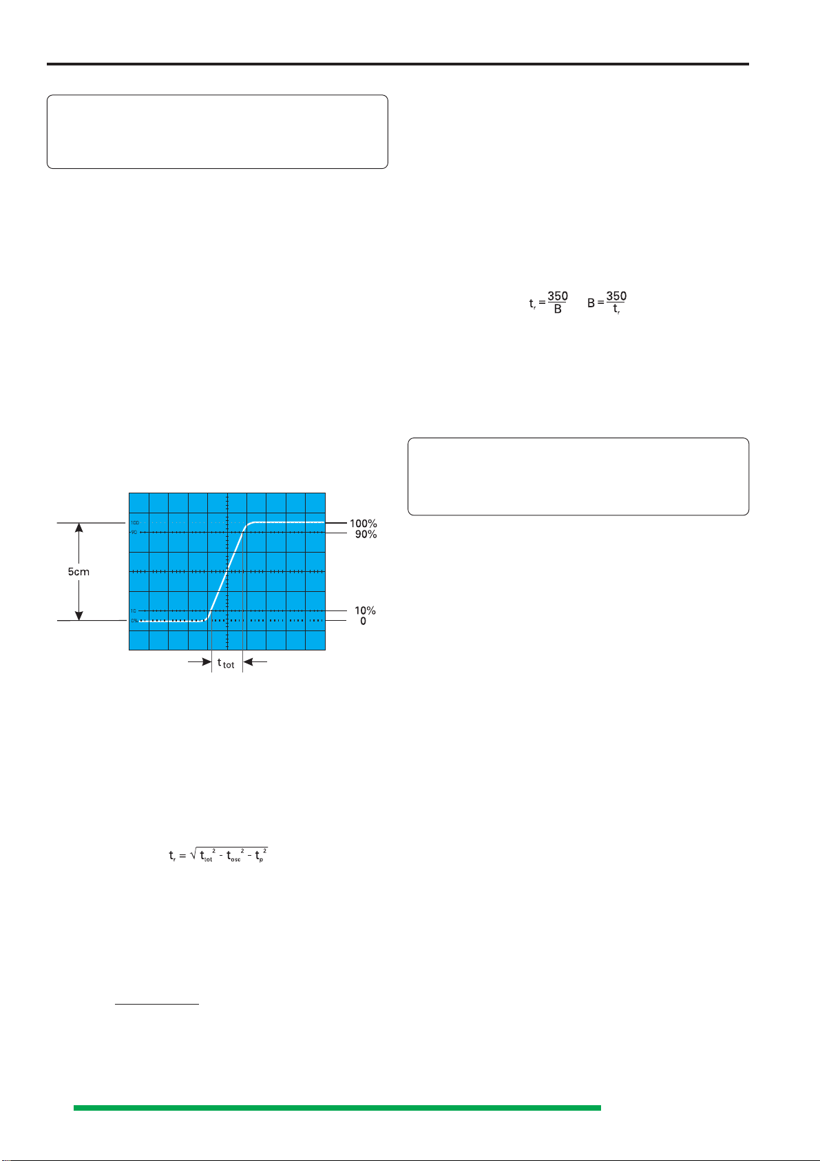
Risetime: <8.75ns. Overshoot: ≤1%.
Deflection coefficient: 14 calibrated positions
variable 2.5:1 to min. 50V/div.
1mV/div and 2mV/div: ±5% (0 to 10MHz (-3dB))
5mV/div to 20V/div: ±3% (1-2-5sequence).
Input impedance: 1MΩII 15pF.
Input coupling: DC - AC - GD (Ground)
Input voltage: max. 400V (DC + peak AC).
Triggering
Automatic(peak to peak):≤≤
≤≤
≤20Hz-100MHz(≤0.5div),
Normal: DC-100MHz, LED for trigger indication.
Slope: positive or negative.
Sources: CH I or II, line, ext.
CH I alternate CH II (≤ 0.8div.)
Coupling: AC (≥10Hz -100MHz), DC (0-100MHz),
HF (50kHz - 100MHz), LF (0 - ≤1.5kHz).
Triggering ext.: ≥0.3Vpp from DC to 100MHz
Active TV-Sync-Separator (field & line, pos, neg.)
2nd triggering (Del. Trig.): normal with level
control DC to 100 MHz.
Horizontal Deflection
Time coefficients: 1-2-5 sequence, Accuracy ±3%
Analog: 22 cal. positions from 0.5s - 50ns/div.
Digital:
25 cal. positions from 100s - 1µs/div.
Variable (analog) 2.5:1 up to 1.25s/div.
X-MAG. x10: analogto10ns/div.,dig.to0.1µs/div ±5%
.
Delay: 120ms - 200ns, variable,
Hold-off time (analog):variable to approx. 10:1.
Bandwidth X-amplifier (analog): 0-3MHz (−3dB).
InputX-amplifierviaChannelII, Sensitivitysee
ChannelII.
X-Y-phase shift : <3° below 120kHz.
Digital Storage
Operating modes: Refresh, Roll, Single, XY,
Envelope, Average (2 to 512 waveforms).
Automatic Dot Join function
Sample Rate: max. 100MS/s (8 bit)
Refresh rate: max. 180/s
Record length: 2048 x 8 bit per channel.
Reference memoryReference memory
Reference memoryReference memory
Reference memory: 2 x 2k x 8bit (EEPROM).
Resolution: Y: 25 points/div, X: 200 points/div.
Pre-/Posttrigger: 25, 50, 75, 100, -25,
-50, -75%.
Operation / Control
Manual (front panel switches);
Auto Set (automatic parameter selection).
Save/Recall of 9 user-defined parameter settings
RS232 interface for remote control via a PC.
Remote control (Option) HZ68.
Multifunction- Interface HO79-6(Option): RS232,
IEEE-488, Centronics (Postscript, HPGL, PCL, EPSON).
Readout: Display of parameter settings.
Cursor measurement of ∆V, ∆t or ∆1/t
(frequency),
separate or in tracking mode.
Component Tester
Test voltage: approx. 7Vrms (open circuit).
Test current: max. 7mArms (short circuit).
Test frequency: approx.50Hz
One test lead is grounded (Safety Earth).
GeneralInformation
CRT: D14-364GY/123 or ER151-GH/-,rectangular
screen (8x10cm) internal graticule
Acceleration voltage: approx 2000V
Trace rotation: adjustable on front panel
Calibrator: square-wave generator (tr<4ns)
≈1kHz/1MHz; Output: 0.2V ±1%.
Analog Intensitymodulation, max. +5V (TTL).
Line voltage: 100-240V AC ±10%, 50/60Hz
Power consumption: approx. 42 Watt at 50Hz.
Min./Max. ambient temperature: 0°C...+40°C
Protective system: Safety class I (IEC1010-1)
Weight: approx. 5.6kg, color: techno-brown
Cabinet: W 285, H 125, D 380 mm 3/98
Auto-Set, Save/Recall, Readout/Cursor, RS232 Interface
Analog: 2 x DC-40MHz, max. 1mV/div, Timebase 0.5s/div - 10ns/div
Triggering DC - 100MHz, Component Tester, 1MHz Calibrator
Digital: Max. Sampling Rate 100MS/s, Timebase 100s/div - 0.1µs/div
Storage 2 x 2048 x 8 bit, Reference Memory, Post/Pre-Trigger
Storage Modes: Refresh, Single, Roll, Average and Envelope
40MHz Analog-/Digital-Scope HM407