Opentech INSOMNIAC CIA G-600 User manual

INSOMNIAC CIA G-600 Gateway
Installation Manual
P/N CIA-675-001
Revision 1.1
Date Code: 6-3-2021

CIA-675-001 Rev 1.1
2 | P a g e
Direct: (602) 773-1700
Main: (800) 481-7459
2101 W Peoria Ave, Suite 100
Phoenix, AZ 85029
support@opentechalliance.com
www.opentechalliance.com
Table of Contents
Table of Figures ...............................................................................................................................................................3
SPECIFICATIONS..............................................................................................................................................................4
INSTALLATION .................................................................................................................................................................5
General: ..........................................................................................................................................................................5
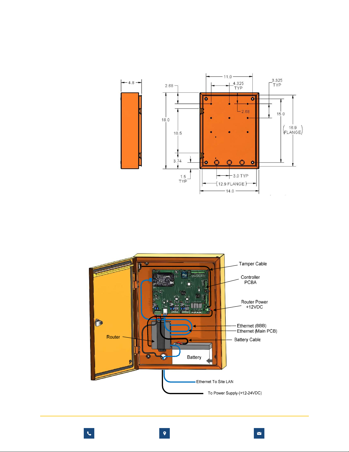
Physical Installation and Mounting .....................................................................................................................5
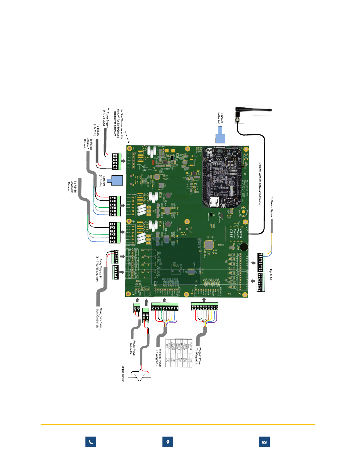
Wiring Connections ...................................................................................................................................................7
Incoming PWR.........................................................................................................................................................8
RS485/ Outgoing PWR ........................................................................................................................................8
RS485 Limitations ..................................................................................................................................................8
Wireless Communications (Optional ..............................................................................................................8
Relay Outputs..........................................................................................................................................................9
Tamper Alarm..........................................................................................................................................................9
Inputs....................................................................................................................................................................... 10
Earth Ground ........................................................................................................................................................ 10
Battery Backup Calculations ................................................................................................................................10
Testing the Gateway Hardware .......................................................................................................................... 11
Power Distribution Calculations and Fuses....................................................................................................12
GATEWAY MAINTENANCE ....................................................................................................................................... 13
Cleaning: ..................................................................................................................................................................... 13
NOTICES and DISCLAIMERS..................................................................................................................................... 13
Liability Disclaimer .................................................................................................................................................. 13
FCC Part 15 Notice .................................................................................................................................................. 13
Looking for a local installer?
We train a network of OpenTech Authorized Dealers throughout the United States.
Visit www.opentechalliance.com/dealers to find one near you!

CIA-675-001 Rev 1.1
3 | P a g e
Direct: (602) 773-1700
Main: (800) 481-7459
2101 W Peoria Ave, Suite 100
Phoenix, AZ 85029
support@opentechalliance.com
www.opentechalliance.com
Table of Figures
Figure 1 - Gateway Components…………………………………………………………………………………………………...5
Figure 2 - Gateway Physical Dimensions................................................................................................................6
Figure 3 - Gateway Baseline (Minimum) Wiring..................................................................................................6
Figure 4 - Gateway Wiring Connections.................................................................................................................7
Figure 5 - Relay Ratings................................................................................................................................................9
Figure 6 - Tamper Alarm Reset ..................................................................................................................................9
Figure 7- Fuses and Indicators ................................................................................................................................ 11
Figure 8 - Fuse to System Size Relationship Diagram.................................................................................... 12

CIA-675-001 Rev 1.1
4 | P a g e
Direct: (602) 773-1700
Main: (800) 481-7459
2101 W Peoria Ave, Suite 100
Phoenix, AZ 85029
support@opentechalliance.com
www.opentechalliance.com
SPECIFICATIONS:
ITEM
DESCRIPTION
FEATURES
1
ENCLOSURE
INDOOR, ALUMINUM, POWER COATED
2
COMMUNICATIONS
RS485 (2) & WIRELESS (900 MHZ), ETHERNET
3
PROCESSOR
AM3358 1GHZ, 512MB
4
FORM-C RELAY OUTPUTS
4
5
SECURE COMMUNICATIONS
YES
6
AUXILIARY INPUTS
8
7
WIEGAND INTERFACE
2
8
MAX OPERATING INPUT
VOLTAGE
24V
9
MIN OPERATING INPUT
VOLTAGE
15V
10
MAX INPUT CURRENT
6A
11
MAX OUTPUT CURRENT
5A TOTAL, 3A PER CHANNEL , 0.75A
ACCESSORY (FIGURE 8)
12
OUTPUT VOLTAGE – RS485
0-2 VOLTS BELOW INPUT VOLTAGE
13
OUTPUT VOLTAGE- ACCESSORY
+5 AND +12 AS MARKED +/- 2%
14
OPERATING TEMP RANGE
32 TO 120 DEG. F.
15
HUMIDITY
0-95% NON-CONDENSING
16
INGRESS RATING
UL294 – INDOOR EQUIPMENT
17
NOMINAL BATTERY VOLTAGE
12V
18
BATTERY BACKUP POWER
8AH (TIME DEPENDS ON SYSTEM CONFIG –
SEE PG 10)
19
UL294 PERFORMANCE LEVEL
LEVEL II

CIA-675-001 Rev 1.1
5 | P a g e
Direct: (602) 773-1700
Main: (800) 481-7459
2101 W Peoria Ave, Suite 100
Phoenix, AZ 85029
support@opentechalliance.com
www.opentechalliance.com
INSTALLATION
General: The gateway is designed to manage access to or from a series of secured areas. It operates in
conjunction with a central database that contains a list of access codes and areas these codes are valid
for. The Gateway communicates with a master database that exists centrally accessible via the internet.
The central database is the source of the access code to access area and access time correlation as wellas
all system configuration information. The Gateway will operate standalone using cached data if internet
connectivity is lost however no changes in access codes or configuration are possible until internet
connectivity to the master database is restored. The Gateway cabinet contains one Main PCB, an Ethernet
Router and a Battery and should be located indoors inside the protected area.
The Gateway can be used to control gate access, building access, door access, elevator access, lighting
and other security related functions that are relay driven however all the control logic must be configuredin
the central database.
Physical Installation and Mounting: The following are instructions on installing and connecting the wiring
run from the system Gateway:
1.
Open the device by unlocking the door with a tool, typically a screwdriver. A security lock on the
front panel is optional.
Figure 1 –
Gateway Components

CIA-675-001 Rev 1.1
6 | P a g e
Direct: (602) 773-1700
Main: (800) 481-7459
2101 W Peoria Ave, Suite 100
Phoenix, AZ 85029
support@opentechalliance.com
www.opentechalliance.com
2.
Mount the back plate to the desired Gateway location, (which must be inside a protected area)
using the 4 grommet filled holes in the back panel shown. There are also a series of knock outs
in the back and the floor of the enclosure for pulling the wires through.
3.
Mount the router and the battery and then pull the necessary wires through the knockouts on the
back of the housing. The router has a bracket to hold it in place, the battery rests free in the cabinet.
After the wire connections are complete, excess wire can be pushed back into the wall or it can be
carefully positioned inside the enclosure for future maintenance and service.
Figure 2 –
Gateway Physical Dimensions
Figure 3 –
Gateway Baseline
(Minimum) Wiring

CIA-675-001 Rev 1.1
7 | P a g e
Direct: (602) 773-1700
Main: (800) 481-7459
2101 W Peoria Ave, Suite 100
Phoenix, AZ 85029
support@opentechalliance.com
www.opentechalliance.com
Wiring Connections: Below is a connection diagram for the Gateway. Note: All installations must conformto
local building and electrical codes and shall be in accordance with the National Electric Code,ANSI/NFPA
70. When discrepancies exist between local codes and this manual, local code takes precedence. All cables
entering the gateway should be insulated and shielded with drain wires connectedto earth ground at one
end. In addition, incoming cables other than the RS485 Cables must be less than 10meters long. The R485
wires should be 18 gauge. Other wires must be between 16- and 26-Gauge wire.
Figure 4 – Gateway Wiring Connections

CIA-675-001 Rev 1.1
8 | P a g e
Direct: (602) 773-1700
Main: (800) 481-7459
2101 W Peoria Ave, Suite 100
Phoenix, AZ 85029
support@opentechalliance.com
www.opentechalliance.com
Incoming PWR: Incoming power (15-24VDC) is connected to the connector at the bottom left-hand
corner of the board. Figure 4 “To Power Supply”. A 24V 5A DC supply is provided by default. One
suggested P/N is SDI120-24-U-P51 by CUI. This is sufficient for systems having up to 6 keypads. If more
devices are required a larger DC supply would be required. The DC supply is to be mounted separately
outside the enclosure.
RS485/ Outgoing PWR: RS485 data communication originate here in 2 connectors (2 parallel channels).
Each will support 16 devices such as keypads and relay modules. We recommend that power and RS485
data communications be via a single 18 AWG, 4-conductor shielded cable. The shield drain wire can be
used as the EARTH common wire. Do not connect more than one RS485 cables to each channel. For each
channel all attached devices shall be connected as an inline chain beginning with the Gateway and ending
with the last device. The last device shall have a “termination” jumper installed as shown in the Keypad and
Relay module manuals. All other devices shall have this jumper omitted.
These RS485 connectors have 6 pins.
DC + V (15-24VDC)
Required
Red
DC – V (DC Common)
Required
Black
Earth
Optional
PCB has earth ground connector on bottom left mounting screw
RS485-A
Required
RS-CMN
Recommended
Can use cable shield
RS-485-B
Required
RS485 Limitations:
A wired keypad can be located up to 4000 feet from the Gateway given proper
twisted
pair
cable with ground wire is used.
To properly terminate cables into connectors the following instructions apply.
1.
Strip back the outer insulation and shield foil from both of the 18 AWG, 4-conductor, shielded cables
being careful not to cut the bare shield wire. Strip ¼ inch of insulation off the end of each of the
individual-colored conductor wires.
2.
Remove the terminal blocks from the keypad circuit board by sliding them up and off. The terminal
blocks may be somewhat difficult to remove as a tight electrical connection is necessary. If they are
tight, rock them slightly back and forth while lifting away from the board.
3.
Insert wires into the desired connector. Where 2 wires are tied together ensure that both wires are
seated all the way inside the slot. Use a flathead precision screwdriver to tighten down the terminal
screw.
4.
Verify that the terminal slot has tightened down on the copper wire and not on the rubber
insulation. There should be no copper wire showing outside of the terminal slot. Gently tug the wires
to verify that they are tightly held inside the terminal slot. Repeat this process with each of the
remaining wire connections.

CIA-675-001 Rev 1.1
9 | P a g e
Direct: (602) 773-1700
Main: (800) 481-7459
2101 W Peoria Ave, Suite 100
Phoenix, AZ 85029
support@opentechalliance.com
www.opentechalliance.com
Wireless Communications (Optional): The Gateway can also function without the RS485 wiring. In this
case the XBEE or XBEE Pro 900 MHZ wireless module and an RPSMA antenna must be installed on the
system Gateway and on the remote device to operate wirelessly. If the keypad or relay unit is within
wireless range of the Gateway, the keypad will work in same fashion as with RS485 connections. The range
depends on the wireless module used, the antenna used, the RF background level of the area (rural or
urban) and the number of obstructions between devices. The XBEE basic module range is up to 300ft
unobstructed line of sight rural area. Typical obstructed range of XBEE in urban areas is 100 ft. The XBEEPro
module range is up to 1 mile w/unobstructed rural line of sight. 500ft obstructed line of sight in urban
areas is common for XBEE Pro. XBEE Pro transmitter modules are recommended. This equipment optionhas
been tested and found to comply with the limits for a Class B digital device, pursuant to Part 15 of theFCC
Rules.
This option has not been evaluated nor certified as part of UL294 level 2 nor CSA C22.2 No.205
Relay Outputs: The Gateway has 4 relays. Relay #1 is reserved for a tamper alarm leaving 3 for field
configuration. Each relay has a Normally Closed (NC), a Common and a Normally Open (NO) connection.
Depending on the need, wire to the common and either the NC or NO. On board LEDs are provided to
show if the relay is activated. Typical gate operators require a normally open contact. Some electric door
strikes require a normally closed contact. If door strikes are used it is recommended that they be DC
(typically 12V) so that a shunting diode must then be installed across the solenoid to prevent ground spikes
from disrupting the keypad communication.
Item
Rating
Contact Type
Single Ag-Alloy (Cd Free)
Rated Load
5A (NO) / 3A (NC) @ 30VDC
Max Switching Voltage
30VDC
Max Switching Current
5A (NO) / 3A (NC)
Figure 5 –Relay Ratings
Tamper Alarm: Relay #1 on the Gateway is the tamper relay. This relay is asserted whenever any device in
the system detects a tamper condition, and this relay will latch until cleared by clicking the following button
from the localcontrol screen (pg_control.htm).
Figure 6 –Tamper Alarm Reset

CIA-675-001 Rev 1.1
10 | P a g e
Direct: (602) 773-1700
Main: (800) 481-7459
2101 W Peoria Ave, Suite 100
Phoenix, AZ 85029
support@opentechalliance.com
www.opentechalliance.com
Inputs: Each Input has a Ground Connection (G) and a Sense Connection (1). The sense connections are
marked 1-8 and will source a small voltage at high impedance. Wire any dry contact across a sense pin and
a G pin. Closing the contact will energize the input. On board LEDs are provided to show if the input is
activated.
Earth Ground: To connect an earth ground wire, run an insulated copper wire (preferably color green)
from a grounded water pipe or from a copper rod in the ground to the gateway and connect it to the
greenearth ground wire using a wire nut. The enclosures earth wire is connected to the stud in the floor of
the enclosure and the door using a screw with a star washer. The PCB’s lower left mounting standoff
providescontinuity of earth ground to the cabinet. This installation must meet applicable code as the type
of wire, depth of burial, and size of the rod may vary by municipality. Note: Uninsulated wires (typically
used for earth ground) cannot be located inside the unit’s case. Make connections for an uninsulated
ground wire outside the enclosure.
Battery Backup Calculations: The Gateway PCB has a built-in battery charger to keep the battery full
charged. The standard 12V Battery (P/N: DURA12-8F or Equivalent) is rated at 8AH which is sufficient to keepa 6
keypad system running for approximately 3 hours if power is interrupted. The following formula is usedto
estimate battery life. Current draw is defined below for 12V input (battery).
•Gateway Draws 300ma + 41 ma per wired relay + 500ma for the router + any accessory power
•Keypads Draw 200ma + 41ma / wired relay + 100ma if RF transmitter is installed + any accessory
power
•Relay unit Draws 200 ma + 41 ma / wired relay + 100ma if RF transmitter is installed
•Example Calculation for 6 keypads w/2 relays used, 1 relay unit w/4 relays used and a Router
8000mah / ((300 + (282 x 6) + (364 x 1) + 500) = 2.8 Hrs

CIA-675-001 Rev 1.1
11 | P a g e
Direct: (602) 773-1700
Main: (800) 481-7459
2101 W Peoria Ave, Suite 100
Phoenix, AZ 85029
support@opentechalliance.com
www.opentechalliance.com
Testing the Gateway Hardware: Test the Gateway by applying power to the Incoming power connection.
There are multiple LEDs as shown below that should be active as described for troubleshooting purposes.
Check the 3 Power Indicator LEDs PCB. If all are dark, check / replace the PCB main fuse. If any single
specific power LED such as the 3.3V or 5V LEDs are dark, replace the main PCB. Note: The Main PCB carries
a Master ID Address called the UID. If this board is changed the new boards UID must be entered in the
central database replacing the previous board’s address before the board will function.
Power Distribution Calculations and Fuses: The main PCB carries 4 important fuses. These are
identified
on the diagram above (figure 7) along with replacement part numbers. The diagram below (figure 8) shows how
these
fuses are arranged.
Each RS485 channel (there are 2 available) can support a maximum of 6 RS485 devices based on the fuses
shown below. All fuses below should be slow blow fuses as the keypads have significant in-rush current.
The number of keypads and their optional accessories are limited per the following diagram. Even though
each keypad has a lot of accessory power, the sum of all devices (i.e., the total energy budget) for the
system as well as each channel must be limited to the fusing. The calculationsmust be done at 12V as that is
the worst-case battery voltage. Lower currents are present when the systemis on 24V power but on power
loss the 12V battery will begin supporting the system and all currents will double.
To avoid blowing fuses system sizing must be done at 12V. The total sum of devices powered from the
gateway must not exceed 5A total, 3A per channel and 1A for accessories. If the router is powered fromthe
gateway, then only .25A remains for accessories at 12V or 5V.
Figure 7 –
Fuses and Indicators

CIA-675-001 Rev 1.1
12 | P a g e
Direct: (602) 773-1700
Main: (800) 481-7459
2101 W Peoria Ave, Suite 100
Phoenix, AZ 85029
support@opentechalliance.com
www.opentechalliance.com
As a default each RS485 channel is fused at 3.1A slow blow fuse. This is sufficient for powering 6 Keypads
and/or Relay Units per channel. If a larger number of devices are required, they must be externally powered
from
a different DC source. If external power supplies are used, DO NOT connect the +V wire of the RS485device
back to the Gateway. Each Keypad / Relay Unit is capable of drawing 3.2W (steady state) with twoactive
relays. If the Wireless option is installed on a device, it will draw another 1.1W but it may be that theunit is
remotely powered from a separate supply in this case as is not wired to the RS485 cable.
Figure 8 – Fuse to System Size Relationship Diagram

CIA-675-001 Rev 1.1
13 | P a g e
Direct: (602) 773-1700
Main: (800) 481-7459
2101 W Peoria Ave, Suite 100
Phoenix, AZ 85029
support@opentechalliance.com
www.opentechalliance.com
GATEWAY MAINTENANCE
Cleaning:
Yearly: Open the Gateway cabinet, inspect and clean the inside of the unit. Remove dirt or dust that has
collected on the inside of the housing and the circuit board that could cause problems. Note any signs of
water damage or corrosion caused by a leak in the enclosure seals. Replace any worn seals. A small canof
compressed air can be used to remove insects and dust from the circuit board.
Battery Maintenance:
Bi-Yearly: Replace the main backup battery (P/N: Duracell DURA12-8F or Equivalent) and the Coin Cell
battery (P/N Panasonic CR1220) on the PCB.
Process for Changing Battery
1. Leave Power ON. This is important.
2. Open Cabinet Door, all items inside are low voltage (<30V)
3. Disconnect Red Battery wire
4. Disconnect Black Battery Wire
5. Remove Battery
6. Replace Battery
7. Reconnect Black wire
8. Reconnect Red Wire
9. Remove Coin Cell battery
10. Replace with new Coin Cell at upper rim of PCB and ensure Coin cell battery (+) side faces you.
11. Test System (see method described on Page 11)
12. Close and secure cabinet door.
NOTICES and DISCLAIMERS
Liability Disclaimer: While every effort has been made to ensure the accuracy of the information in this
document, there is no lability for any inaccuracies contained herein. We reserve the right to change the
information contained herein at any time and without notice.
FCC Part 15 Notice: This equipment has been tested and found to comply with the limits for a Class B digital
device, pursuant to Part 15 of the FCC Rules. These limits are designed to provide reasonable protection
against harmful interference in a residential installation. This equipment can generate and radiate radio
frequency energy and, if not installed and used in accordance with the instructions, may cause harmful
interference to radio communications.
Table of contents
Popular Gateway manuals by other brands

MaxLong
MaxLong MG8322 user manual

enphase
enphase 400 A Consumption CTs Installation instruction

AT&T
AT&T U-verse TV Get started

Hored
Hored M1 user manual

Grandstream Networks
Grandstream Networks BroadWorks BroadSoft GXW-400X Configuration guide

HMS Networks
HMS Networks Intesis IN701-KNX Series user manual