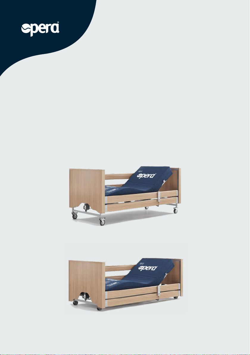
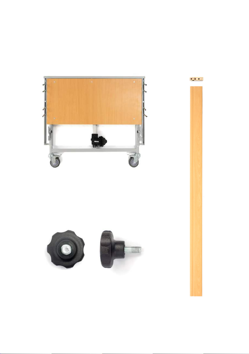
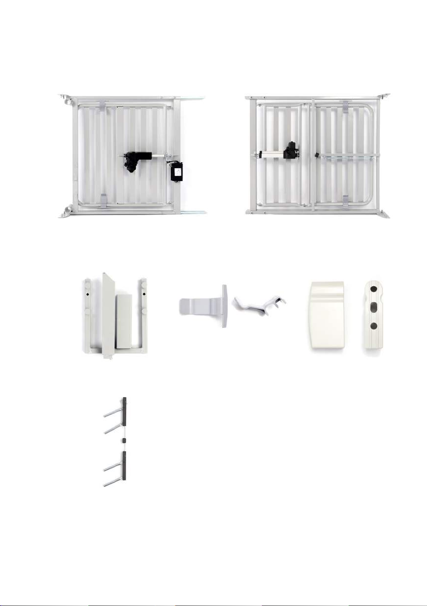
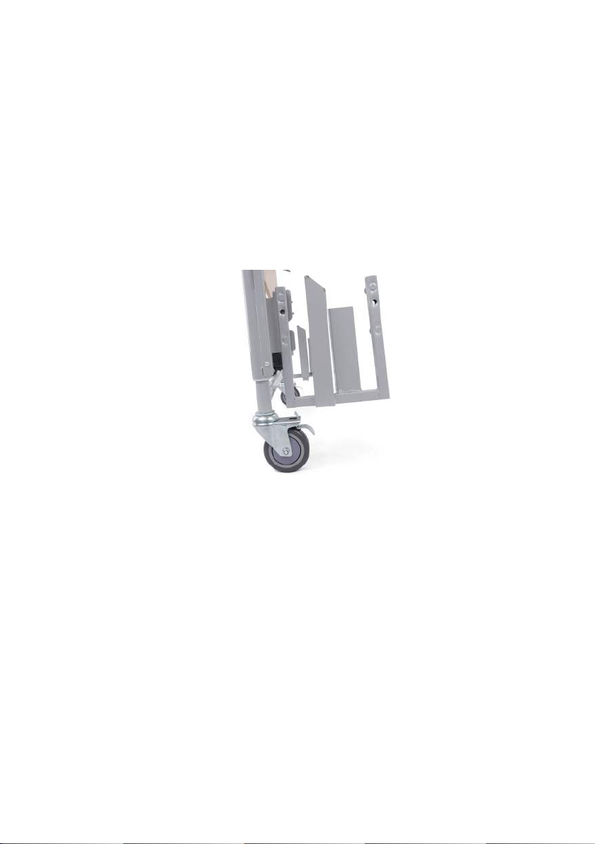
Opera Classic User manual
Other Opera Indoor Furnishing manuals

Opera
Opera IMPULSE AUTO User manual

Opera
Opera MAM001-30 User manual

Opera
Opera Serene Profiling User manual

Opera
Opera FLO User manual

Opera
Opera BPL002-OR User manual

Opera
Opera ULTIMATE User manual

Opera
Opera Classic User manual

Opera
Opera Static User manual

Opera
Opera Relieve Overlay User manual

Opera
Opera Classic User manual


Popular Indoor Furnishing manuals by other brands

Regency
Regency LWMS3015 Assembly instructions

Furniture of America
Furniture of America CM7751C Assembly instructions

Safavieh Furniture
Safavieh Furniture Estella CNS5731 manual

PLACES OF STYLE
PLACES OF STYLE Ovalfuss Assembly instruction

Trasman
Trasman 1138 Bo1 Assembly manual

Costway
Costway JV10856 manual