Opera Signature Series User manual

opera-care.co.uk | 0333 222 8584
Signature Bed
Installation Guide
and Technical
Specications

1| Opera Care Signature Installation Guide and Technical Specication | Version 2
1. Explanations of Symbols 2
2. Installation and Commissioning 3
3. Bed Operation and Maintenance 23
4. Troubleshooting 27
5. Safety Instructions 28
6. General Information 33
7. Servicing 36
8. Technical Specication 39
9. Service Life and Disposal 46
10. Guarantee 47
11. Opera Warranty Terms and Conditions 47
Contents

2
opera-care.co.uk | 0333 222 8584 |
Read information with this symbol carefully and urgently follow instructions.
This information is safety-relevant.
This symbol indicates hazards due to electrical voltage. There is mortal danger!
This symbol indicates general hazards. There is danger to life and health.
Conformity mark in accordance with the Medical Device Directive (93/42 EEC).
The electrical equipment is splash-proof.
Symbol for Protection Class II device, double shock-proof.
Symbol for type B device according to DIN EN 60601-1.
This care bed may only be used indoors
This product must be disposed of in a separate refuse collection in the European
Union. Do not dispose of as normal domestic waste.
Symbol for direct current.
Symbol for alternating current.
Maximum permissible load.
Maximum patient weight.
Read instructions
DANGE R
ELECT RICAL
IPX4
i
1. Explanations of Symbols
3| Opera Care Signature Installation Guide and Technical Specication | Version 2
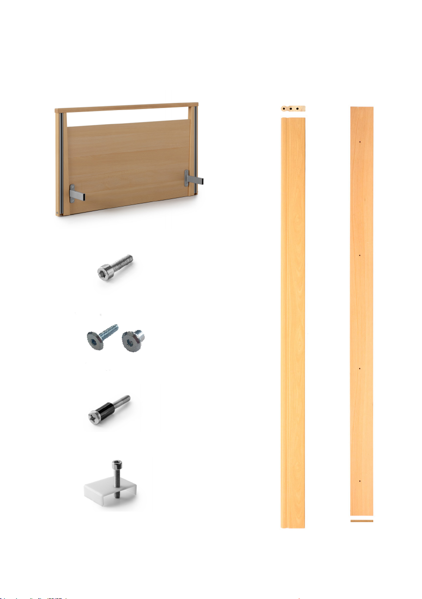
(E) Chassis Securing Bolt x 4
* Eight of these are already tted to the Mattress Platform Backrest Section
** These items are already tted to the Head/Footboards
*** These items are already tted to the Mattress Platform Sections
**** Foot and headboards styles vary
(A) Head/Footboard**** x 2 (F) Side Rail x 4
(C) Side Skirt Fixing Bolt and Insert Nut x 8
(D) Side Rail Channel Fixing Bolt** x 4
(B) Mattress Platform Securing Bolt* x 16
(G) Side Skirt x 2
2. Installation and Commissioning
2. Installation and Commissioning

4
opera-care.co.uk | 0333 222 8584 |
(H) Mattress Backrest platform
N.B. Easily identiable because it has both an actuator
and the black control box.
(I) Mattress Legrest platform
N.B. Easily identiable because it only has one actuator.
(K) Mattress Retainers*** x 4(J) Bed Chassis (L) Side Rail End Cap x 8
(O) Power Transformer
(N) Handset
(M) Side Rail Runner x 4
Before you begin, you will also need:
• Wall space with a plug socket nearby
• Tools: 4mm & 6mm Allen Key, A cross head screw driver, Pair of scissors
2. Installation and Commissioning

5| Opera Care Signature Installation Guide and Technical Specication | Version 2
Place accessories to one side
Detach the following accessories and place to one side:
(B) Mattress Platform Securing Bolt x 16
(C) Side Skirt Fixing Bolt and Insert Nut x 8
(E) Chassis Securing Bolt x 4
(L) Side Rail End Cap x 8
(M) Side Rail Runner x 4
Position the bed
Move the bed into the centre of the room.
Place the side rail and side skirt boxes to one
side.
Read before you begin! We recommend that two people install this bed due to
the weight of individual parts.
1
2
B
x 16
C
x 8
E
x 4
L
x 8
M
x 4
2. Installation and Commissioning
6
opera-care.co.uk | 0333 222 8584 |
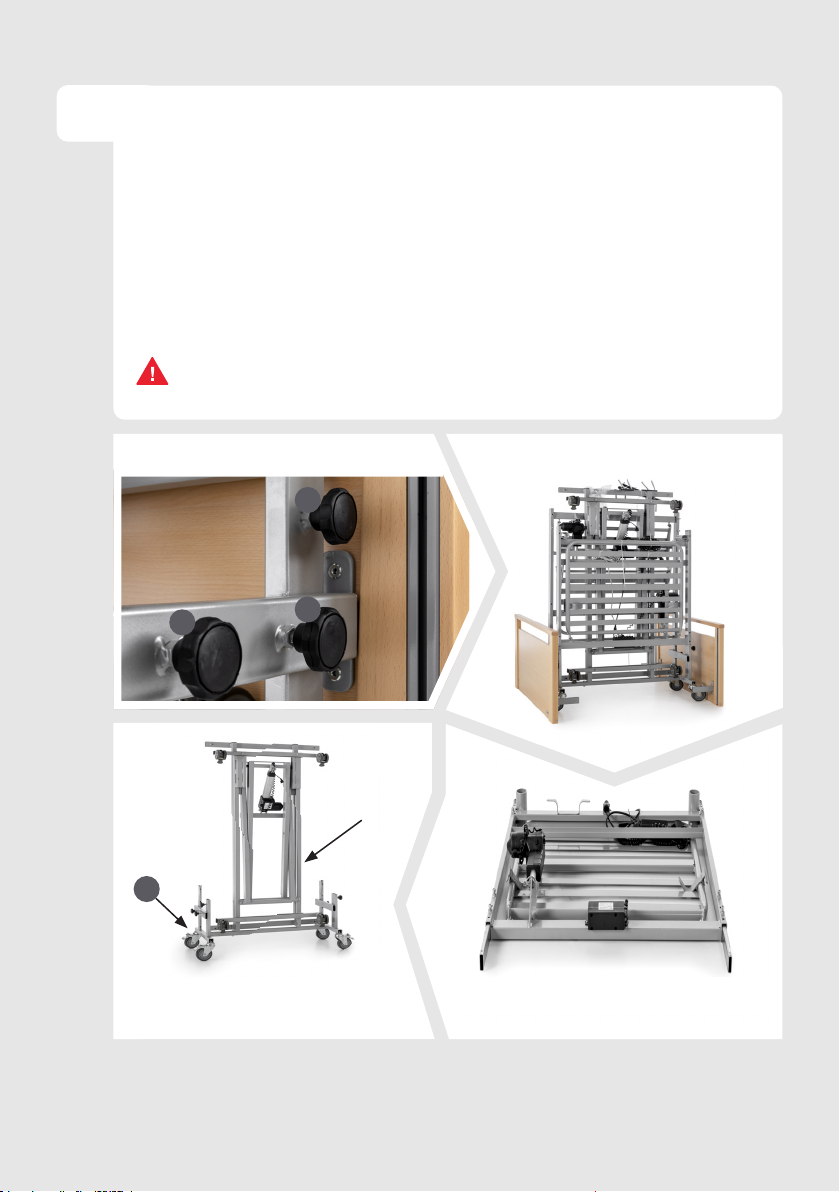
Remove head/footboards and mattress
platforms from the transportation bracket
Loosen the thumb screws (1) on each side of the transportation bracket,
and slide the head and footboards (A) out of the bracket. Place the
detached boards to one side. Lift the mattress platform sections out of the
transportation bracket, place these to one side with the actuator motors
facing up/on top of the sections.
3
ATTENTION: The bed parts are heavy, please observe the general rules of manual
handling to prevent strain and injury.
1
1
1
Transportation bracket thumb screws Head/footboard detached
Mattress platform sections
detached, leaving the chassis in the
transportation bracket
A
A
1
J
Mattress backrest platform with the
actuator motor on top
2. Installation and Commissioning
7| Opera Care Signature Installation Guide and Technical Specication | Version 2
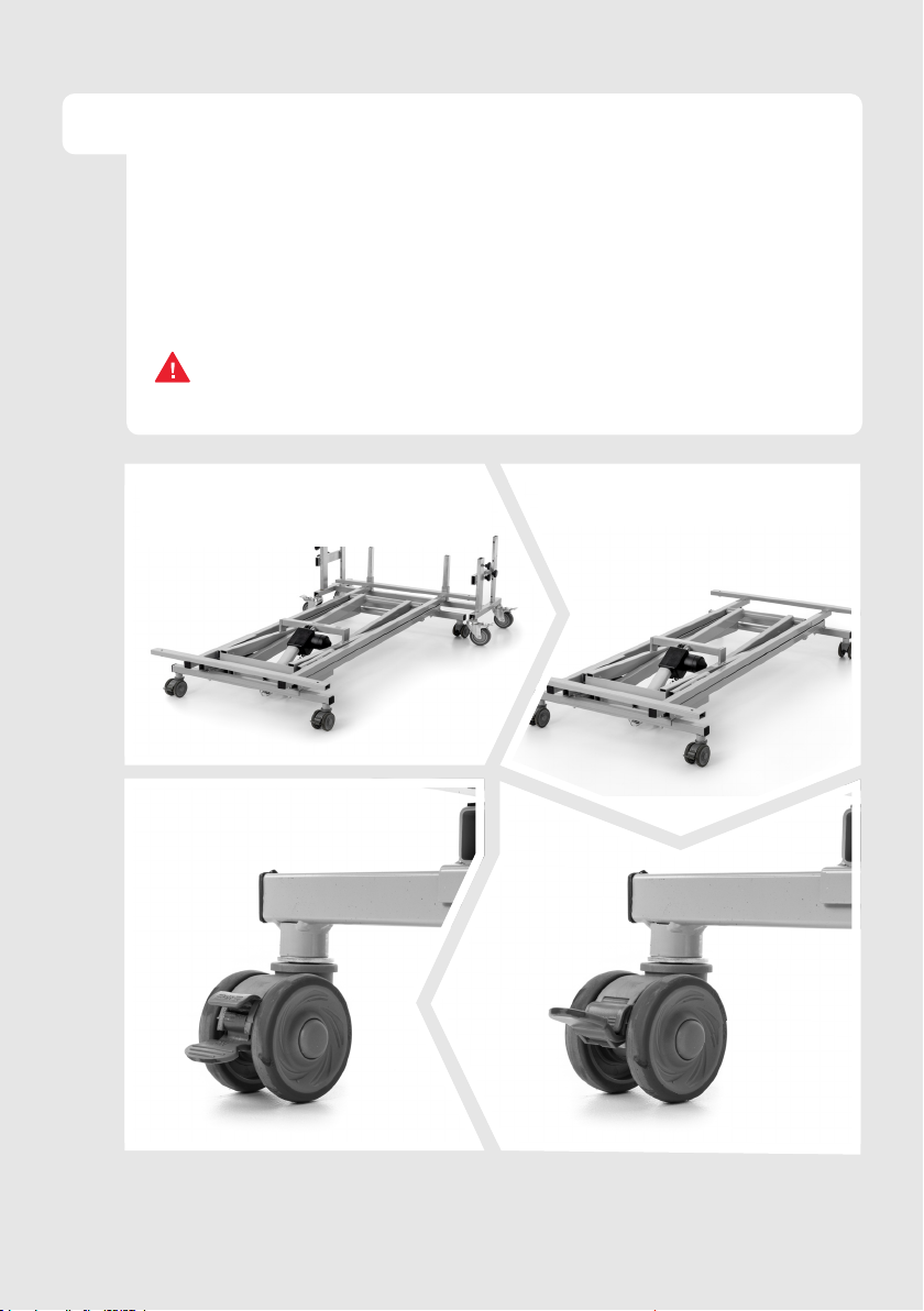
Position the bed chassis
With two people lower the bed chassis (J) down on to the oor. Next,
carefully lift the chassis off the transportation bracket and place down.
Move the transportation bracket to one side. Once the chassis is
positioned, brake all four castors of the chassis by pressing down on the
brake peddles.
4
ATTENTION: The bed chassis is heavy, please observe the general rules of manual
handling to prevent strain and injury.
JJ
Chassis lowered down in the
transportation bracket Chassis with transportation bracket
removed
Brake Off
Brake On
2. Installation and Commissioning

8
opera-care.co.uk | 0333 222 8584 |
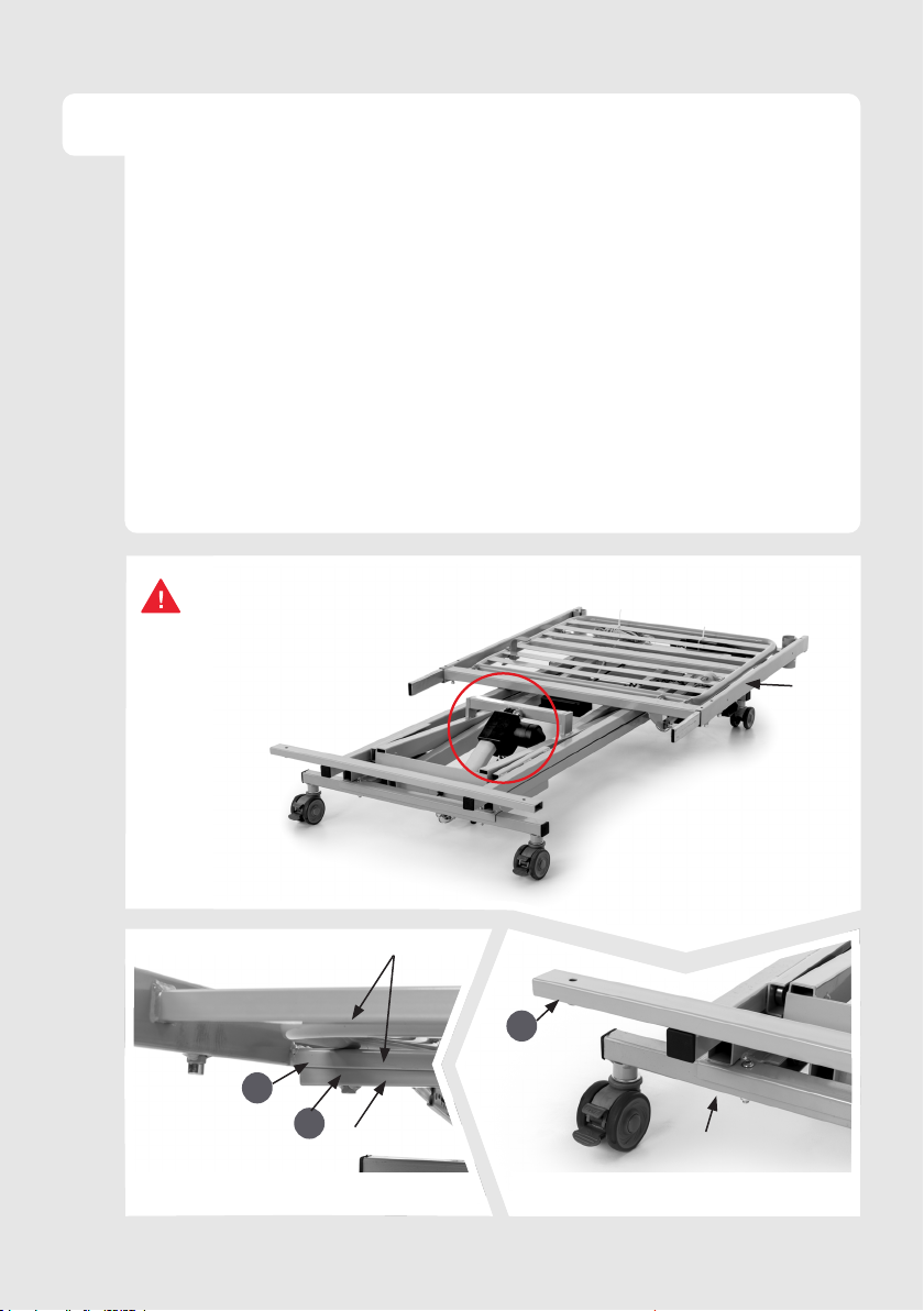
5Secure the actuator motor
Lay down the mattress legrest platform (I)
with the actuator motor facing up (2).
On the actuator securing bracket (3) pull
back the metal guard and remove the pin
(4). Align the holes in the actuator to the
bracket (this is where the pin was). Insert
the pin through the holes and pull the metal
guard back over the pin to secure the actuator in place. Repeat for the
mattress backrest platform.
3344
22
I
Actuator not aligned Pin removed and holes aligned
Pin inserted
Pin inserted with guard in place
2. Installation and Commissioning
9| Opera Care Signature Installation Guide and Technical Specication | Version 2
6Place the backrest mattress platform on the
bed chassis
Lift the mattress backrest platform (H) onto the head end of the bed
chassis (as per the photos below). Ensure that the mattress backrest
platform is not placed above the height adjustment actuator/motor on the
chassis.
Position the mattress backrest platform so that the securing bar (5) at the
head end of the chassis is placed into the U bracket of the backrest (6).
ATTENTION:
Do NOT place the mattress platform
backrest section over the actuator/
motor on the bed chassis.
H
55
66
H
JJ
55
U bracket placed over security bar Security bar
2. Installation and Commissioning
Table of contents
Other Opera Indoor Furnishing manuals

Opera
Opera ULTIMATE User manual

Opera
Opera Static User manual

Opera
Opera Classic User manual

Opera
Opera Serene Profiling User manual

Opera
Opera IMPULSE AUTO User manual

Opera
Opera FLO User manual

Opera
Opera MAM001-30 User manual

Opera
Opera Relieve Overlay User manual

Opera
Opera FLO AUTO User manual

Opera
Opera BPL002-OR User manual


Popular Indoor Furnishing manuals by other brands

Regency
Regency LWMS3015 Assembly instructions

Furniture of America
Furniture of America CM7751C Assembly instructions

Safavieh Furniture
Safavieh Furniture Estella CNS5731 manual

PLACES OF STYLE
PLACES OF STYLE Ovalfuss Assembly instruction

Trasman
Trasman 1138 Bo1 Assembly manual

Costway
Costway JV10856 manual


