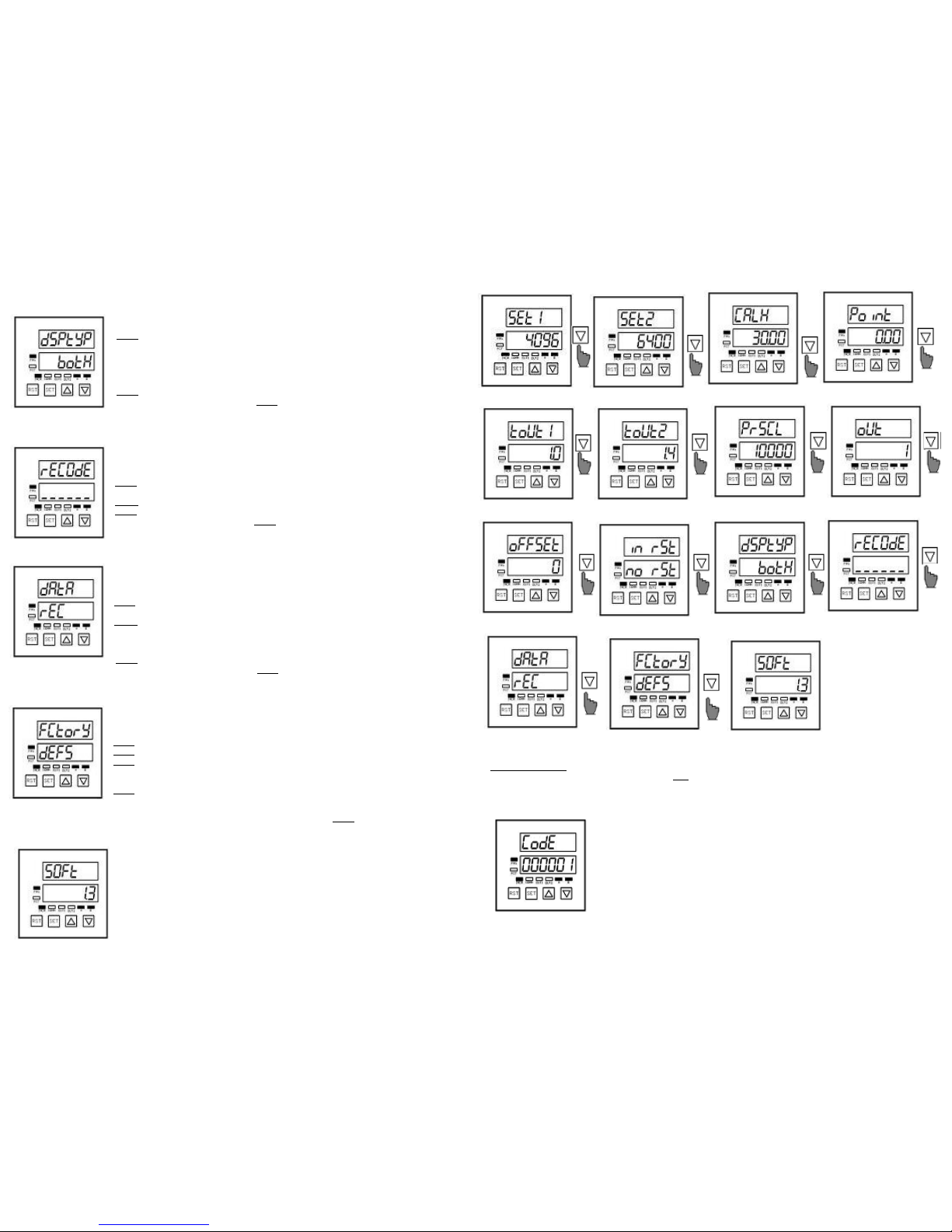
manuals.online logo
Brands
  1. Home
  2. •
  3. Brands
  4. •
  5. Opkon
  6. •
  7. Cash Counter
  8. •
  9. Opkon OP-CN4 User manual

Opkon OP-CN4 User manual

ELECTRICAL CONNECTION
Manufacturer:
Terazidere Mah.60.Yil Cad.No:5/3
34035 Bayrampasa/ISTANB L/T RKEY
TEL: 0 212 501 48 63
FAX: 0 212 501 48 83
Email: [email protected]
MODEL OP-CN
UNIVERSAL
INCREMENTAL
COUNTER
Ver 2.0E
USER GUIDE
WARNING!
READ CAREFULLY BEFORE POWER ON
1. Complete electrical connections according to the
schematic at the last page.
2. Check Supply Voltage 220V (or 2 V optional) AC, or DC, due to
Specifications on the equipment.
3. Use only shielded cable for sensors.
4. Keep away the equipment from direct heat source.
5. MODEL OP-CN is not suitable for outdoor use.
6. Keep away the equipment from water or other liquid
drains.
7. Do not open, modify or replace any component in the
equipment, If any problem occurs please contact an authorised
OPKON technical service or OPKON directly.
ELECTRICAL SPECIFICATIONS:
Microcontroller based
A /B /Z(Reset)-4 X Counter mode
200 kHz Max. counting frequency
2 X Relays output
1 X SSR output
Incremental or absolute positioning mode
Holding on the last value in memory
10 X Output modes
Offset calibration
Password to protect menus
Power Supply :220V ± % 20 (or 24V optional) ,50 Hz
Power Consumption :<4 VA (protected by fuse 50mA)
Sensor supply voltage :+5V or +12VDC (selectable by jumper)
Sensor supply current :Max.100mA(no fuse)
Relays max. ratings :Relay1 1xNO+NC 8A,230V AC
Relay2 1xNO+NC 8A,230V AC
SSR output :5V DC (non-isolated)
MECHANICAL SPECIFICATIONS:
Dimensions :72x72x90 mm
Panel cut dimensions :67x67mm
Body :ABS plastic
Working temperature :0-60 ºC
Storage temperature :-10ºC …+80ºC
Humidity :<%90 RH
DESCRIPTIONS
B TTONS
1. Resets the counter.
2. Escapes from program menu. CO NTER DISPLAY
1. Enters to program menu.
2. Shifts the rows When
programming parameters
PARAMETER DISPLAY
1. Travels in menu.
2. Changes the program
LED INDICATORS
Turns on when equipment programming Indicates Communication RS232(optional).
Turns on when press RST button. O T1- O T2 İndicates that Relay1- Relay2 is activated
Indicates that the value on counter display A-B indicates the A-B counting inputs from sensor
is Incremental value. By presing P/DOWN
buttons you can see calibrated value.
MODEL-CN MAIN MENU
When normal working mode ;
-Press SET button to Enter Main Menu
- pper display shows Count value, - Press UP/DOWN buttons to see all
- Lower display shows SET1 Parameter value Parameters in the Menu
MODEL OP -CN OUTPUT TYPES
11. dSPtyP
This parameter defines screen format.Available 3 states;
• Press SET button to enter the submenu When stay on dSPtyP
• Please refer to " enterring the CodE."
•
Press . UP/DOWN buttons and select one of this condition.
1. INC: Screen shows INCREMENTAL Value.
2. LEngtH : Screen shows MEAS RING Value.
3. Both : By P/DOWN buttons can be see INC/Measuring values.
• Press SET button to save.
• If u want to back menu without saving Press RST button (ESCAPE).
• Then equipment backs to main menu automatically.
12. rECodE
This Parameter is used to Change the Password(COdE).If the new Password is written “000000” then
the Equipment do not ask any Password.
• Press SET button to enter the submenu When stay on rECodE.
• Please refer to " enterring the CodE."
• Press UP/DOWN buttons to write new CodE.
• Press SET button to save.
• If u want to back menu without saving Press RST button (ESCAPE).
• Then equipment backs to main menu automatically.
13. dAtA
This parameter is used to HOLD or DELETE the last counter value in the Memory While the Equipment
is switched down electricaly.Available 2 states;
• Press SET button to enter the submenu When stay on dAtA
• Please refer to " enterring the CodE."
• Press . UP/DOWN buttons and select one of this condition.
1. rEC : Counter value is stored on memory.When power turns on, counting value comes to screen.
2. CLear : Counter value is not stored on memory.When power turns on counting value starts from
oFFSEt value.
• Press SET button to save.
• If u want to back menu without saving Press RST button (ESCAPE).
• Then equipment backs to main menu automatically.
1 . FCtory
This Parameter helps to turn the factory settings.This parameter has a specific code.To turn the factory
settings;
• Press SET button to enter the submenu When stay on FCtory
• Press UP/DOWN buttons to write “352947” on display.
• Press SET button.trUe appears for 2 seconds.
• At the end of the 2 second, rEStrE(ReStore) appears on the upper display ,and
dEFS(dEfaults) appears on the lower display.
• Press SET to turn the factory settings.
• LodnG (loading) appears on the display for 3 second.The equipment turns the factory
settings end of the 3 seconds.
• If u want to back menu without turning the factory settings Press RST button (ESCAPE).
• Then equipment backs to main menu automatically.
15. SoFt
This parameter shows the version of the software.
ENTERING “CODE”
For Changing any Parameter, Stay on and Press SET button.Program will ask “CodE” to enter.
Entering the code is shown below;
• ENTER CodE by UP/DOWN buttons
• CodE is “000001” by factory settings.
• Pres SET button to enter the code.
• If the code is correct,for 2 seconds .TrUE will be shown on display.
• Then you do not need to re-enter code during programming.
• For changing CodE please refer submenu Settings.(11-rECodE).
SUBMENU SETTINGS
1. SEt1
SEt1 is the value of Relay1 turns active. (please refer to tOut1 for duration of activation of Relay1).
• Press SET button to enter the submenu When stay on SEt1.
• Please refer to " enterring the CodE."
• Press UP/DOWN buttons to set the value
• Press SET button to shift the row on left.
• After setting all the rows Press SET button finally to save the value.
• If u want to back menu without saving Press RST button (ESCAPE).
• Then equipment backs to main menu automatically.
2. SEt2
SEt2 is the value of Relay2 turns active. (please refer to tOut2 for duration of activation of Relay1).
• Press SET button to enter the submenu When stay on SEt2
• Please refer to " enterring the CodE."
• Press UP/DOWN buttons to set the value
• Press SET button to shift the row on left.
• After setting all the rows Press SET button finally to save the value.
• If u want to back menu without saving Press RST button (ESCAPE)
• Then equipment backs to main menu automatically.
3. CALH (CALIBRATION)
MODEL-CN5 is an Incremental Counter, as well as owing to scaled and calibrated, it is operated as a
Distance/Angel Measurement Equipment. Therefore,occured the LENGTH by Sensor movement
mechanically is matched the Value seen on the screen.
Sample: When the Senor makes 5000 pulse movement Mechaically,
In order to see 100.00 on the screen;
• Move the sensor to the designated position mechanically.
• Press RST button to zero the counter display.
• Move on the sensor to make 5000 pulse on the display.
• After the 5000 pulse occured Press SET button to enter the main menu.
• Press DOWN button for 3 times and stay on CALH submenu. • Press .SET button to enter the submenu.
• Please refer to pg.5 for enterring the CodE • Press UP/DOWN buttons and write “0100.00”.
• After setting all the rows Press SET button finally to save the value • Then equipment backs to main menu automatically.
• Anymore,While the INCR mode is not used, for 5000 Pulse 100.00 is written on the screen.(Look at dSPtYP for INCR mode).
. Poınt
This Parameter defines the Decimal Point.
• Press SET button to enter the submenu When stay on Poınt.
• Please refer to " enterring the CodE."
• Press UP/DOWN buttons to shift the point.
• Press SET button to save the point
• If u want to back menu without saving Press RST button (ESCAPE).
• Then equipment backs to main menu automatically.
5. toUt1
This parameter is used to keep in active durationof the RELAY1 in seconds(s). Sample: For 1 second
duration of RELAY1;
• Press SET button to enter the submenu When stay on toUt1.
• Please refer to " enterring the CodE."
• Press UP/DOWN buttons to write “00001 0” on the display..
•
Press
SET button to save.
• If u want to back menu without saving Press RST button (ESCAPE).
• Then equipment backs to main menu automatically.
• Write to display “000000” for duration continuosly (HOLD)
6. toUt2
This parameter is used to keep in active durationof the RELAY2 in seconds(s). Sample: For 1.4 second
duration of RELAY2;
• Press SET button to enter the submenu When stay on toUt2.
• Please refer to " enterring the CodE."
• Press UP/DOWN buttons to write “00001 4” on the display..
• Press SET button to save.
• If u want to back menu without saving Press RST button (ESCAPE).
• Then equipment backs to main menu automatically.
• Write to display “000000” for duration continuosly (HOLD).
7. PrSCL
This parameter is used as a Multiply Coefficient.In CALH Parameter setup,If the right value is not able
to been create mechanicly, the Calibration can been made by calculating the coefficient
Mathematically.Write it in space 0.001<PrSCL<99000 .
When the PrSCL value changed,the Previous Calibration data is deleted automaticaly.
• Press SET button to enter the submenu When stay on PrSCL.
• Please refer to " enterring the CodE."
• Press UP/DOWN buttons to write the calculated value.
• Press SET button to save.
• If u want to back menu without saving Press RST button (ESCAPE).
• Then equipment backs to main menu automatically.
8. oUt
This parameter is used to define the Operation Types of the Realy1 and Relay2.please refer O TP T
TYPES
• Press SET button to enter the submenu When stay on o t.
• Please refer to " enterring the CodE."
• Press UP/DOWN buttons to write among 0-9 a number .
• Press SET button to save.
• If u want to back menu without saving Press RST button (ESCAPE).
• Then equipment backs to main menu automatically.
9. oFFSEt
This Parameter is used to define the initial value of the Counter, When Pressed the RST button or an
external Z/Reset Pulse enabled.After this Resettlement the counter count forward or reverse from new
OFFSET value. The Default Counter value is zero
• Press SET button to enter the submenu When stay on oFFSEt.
• Please refer to " enterring the CodE."
• Press UP/DOWN buttons to write the ofset value.
• Press SET button to save.
• If u want to back menu without saving Press RST button (ESCAPE).
• Then equipment backs to main menu automatically.
10. ınrST
This Parameter is used to define that, in which EDGE of External Z/Reset pulse, the Counter will
reset.Available 3 states
• Press SET button to enter the submenu When stay on ınrSt.
• Please refer to " enterring the CodE."
• Press . UP/DOWN buttons and select one of this condition.
1. norSt :Disable Z/Reset.
2. FALL :Triggered by the falling edge of Z/Reset.
3. .riSE :Triggered by the rising edge of Z/Reset.
• Press SET button to save.
• If u want to back menu without saving Press RST button (ESCAPE).
• Then equipment backs to main menu automatically.

Popular Cash Counter manuals by other brands

CashConcepts CCE 400 manual

CashConcepts

CashConcepts CCE 400 manual

Particle Measuring Systems HandiLaz Mini Operator's manual

Particle Measuring Systems

Particle Measuring Systems HandiLaz Mini Operator's manual

Eaton Durant Courier 5330 403 Series Installation and operation

Eaton

Eaton Durant Courier 5330 403 Series Installation and operation

Hejm Automation MC331 Technical manual

Hejm Automation

Hejm Automation MC331 Technical manual

Easson ES-1M Operation manual

Easson

Easson ES-1M Operation manual

Velleman DVM13MFC2 user manual

Velleman

Velleman DVM13MFC2 user manual

MULTISPAN LC-2046 manual

MULTISPAN

MULTISPAN LC-2046 manual

HP 53132A Assembly and service manual

HP

HP 53132A Assembly and service manual

Amrotec MiB-1 Service manual

Amrotec

Amrotec MiB-1 Service manual

HYOSUNG NH-2700 manual

HYOSUNG

HYOSUNG NH-2700 manual

HP 53150A Series Programming guide

HP

HP 53150A Series Programming guide

DIEBOLD NIXDORF CS 7790 operating guide

DIEBOLD NIXDORF

DIEBOLD NIXDORF CS 7790 operating guide

Lighthouse RLPC 0.1m operating manual

Lighthouse

Lighthouse RLPC 0.1m operating manual

Beckmann EMS-58 operating manual

Beckmann

Beckmann EMS-58 operating manual

Leica Microsystems DARKFIELD QUEBEC 3325 instruction manual

Leica Microsystems

Leica Microsystems DARKFIELD QUEBEC 3325 instruction manual

DIEBOLD NIXDORF CS 7780 operating guide

DIEBOLD NIXDORF

DIEBOLD NIXDORF CS 7780 operating guide

Vega SI-13-485 user manual

Vega

Vega SI-13-485 user manual

CashTester BC 231 SD user manual

CashTester

CashTester BC 231 SD user manual

manuals.online logo
manuals.online logoBrands
  • About & Mission
  • Contact us
  • Privacy Policy
  • Terms and Conditions

Copyright 2025 Manuals.Online. All Rights Reserved.