Metasys 2400AT Service manual

Fire Initiating Devices and Notification Appliances Technical Manual 408
Conventional Products Section
Technical Bulletin
Issue Date 1095
© 1995 Johnson Controls, Inc. 1
Code No. LIT-408145
Introduction Page 3
●
General Description 4
Installation Procedures 7
●
General Information 7
●
Mounting 7
●
Spacing 8
●
Wiring Installation Guidelines 8
●
Installation 9
●
Tamper-Proof Feature 10
Testing and Maintenance Procedures 11
●
Testing 11
●
Maintenance 13
●
Limitations of Smoke Detectors 15
●
Limitations of Sounders 16
2400AT and 2400AIT Direct 2-Wire Smoke Detector

2 Conventional Products—2400AT and 2400AIT Direct 2-Wire Smoke Detector

Conventional Products—2400AT and 2400AIT Direct 2-Wire Smoke Detector 3
Introduction
This document contains important information about installing and
operating 2400AT and 2400AIT direct wire smoke detectors. These
conventional detectors are manufactured by System Sensor for use with
Johnson Controls systems. If you install this detector for someone else to
use, you must leave a copy of this document with the user.
These instructions provide information regarding mounting, spacing,
wiring, installation, testing, and maintenance. Follow only those
instructions that apply to the model you are installing.
Before you install any 2400AT and 2400AIT direct wire detectors, read
and be familiar with:
●The Guide for Proper Use of System Smoke Detectors Technical
Bulletin in the Fire Initiating Devices and Notification Appliances
Technical Manual (FAN 408) that provides detailed information on
detector spacing, placement, zoning, wiring, and special applications
●or, for non-United States installations, applicable codes and standards
specific to the country and locality of installation.
Failure to follow these directions may result in failure of this device to
report an alarm or trouble condition or respond properly to an alarm
condition. Johnson Controls is not responsible for devices that have been
improperly installed, tested, or maintained by others.

4 Conventional Products—2400AT and 2400AIT Direct 2-Wire Smoke Detector
!
CAUTION: Equipment hazard. Do not use in potentially
explosive atmospheres. Do not leave unused
wires exposed.
The 2400AT and 2400AIT photoelectronic smoke detectors, listed to
UL 268, provide open area protection and are intended for use with
UL Listed, compatible, 2-wire control panels. The sensor in this detector
operates on the light scattering principle and features a unique photo-optic
sensing chamber that optimizes smoke entry while minimizing the effects
of ambient light.
These detectors also provide restorable, 135°F fixed-temperature heat
detection. The 2400AT heat detection unit is integrated with the
photoelectronic detector; in contrast, the 2400AIT’s heat detection unit is
isolated from the photoelectronic smoke detector and can be monitored
separately. In addition, a piezoelectric horn in each detector produces an
interrupted, 85 dBA tone when the individual detector alarms or when the
supply voltage polarity is reversed.
A Light Emitting Diode (LED) on each detector lights to provide a local
alarm indication. When the control panel receives the alarm signal, the
supply polarity is reversed on the system to sound all the devices. Once
the signal circuit is deactivated, the polarity is reset to the original state.
A screw terminal is provided for a remote LED annunciator optional
accessory (RA400Z). These detectors also have the latching feature.
The alarm can be reset only by momentary power interruption.
Table 1: 2400 Series Direct Wire Smoke Detectors
Model Control Description Operating Current Consumption
Panel Voltage Standby
(Min) Alarm
(Max)
2400 2-wire Photo Detector 12/24 VDC 120 µA —
2400TH 2-wire Photo Detector with Fixed
Heat Sensor 12/24 VDC 120 µA —
2400AT 2-wire Photo Detector with Fixed
Heat Sensor and Horn 24 VDC 120 µA 67 mA
2400AIT 2-wire Photo Detector with
Isolated Heat Sensor 24 VDC 120 µA 67 mA
2412AT 4-wire Photo Detector with Fixed
Heat Sensor and Horn 24 VDC 120 µA 51 mA
2424AT 4-wire Photo Detector with Fixed
Heat Sensor and Horn 24 VDC 120 µA 43 mA
2424AIT 4-wire Photo Detector with
Isolated Heat Sensor and
Horn
24 VDC 120 µA 43 mA
General
Description

Conventional Products—2400AT and 2400AIT Direct 2-Wire Smoke Detector 5
Table 2: Specifications Summary
Specifications
Diameter 5.5 in. (140 mm)
Height 3.19 in. (81 mm)
Add 0.5 in. (13 mm) for thermal units.
Weight 0.7 lb (310 g)
Air Velocity 3,000 ft/min. (15 M/s)
Operating Temperature 0 to 38°C (0 to 100°F)
Operating Humidity 10 to 93% RH, Non-condensing
Visual Indicator Solid-state LED
Latching Alarm Reset by Momentary Power Interruption
Audible Signal 85 dBA minimum interrupted tone when in
alarm or supply voltage polarity is reversed
Detector Sensitivity Setting 3.0 ± 0.7%/Ft
Fixed Temperature Heat Detector 135°F (57°C)
Electrical Ratings
System Voltage 24 VDC
Maximum Ripple Voltage 4 volts Peak-to-Peak
Reset Voltage 2.5V
Reset Time 0.3 Seconds
Start-up Capacitance 0.02
µ
F Maximum
Startup Time 36 Seconds Maximum
Voltage Limits 10 to 32 VDC
Current Limits
Standby 120
µ
A Maximum
100
µ
A Nominal
Alarm Current 15 mA at 10V
67 mA at 32V
48 mA at 24V
Reversed Supply* 5 mA at 10V
19 mA at 32V
15 mA at 24V
Alarm Impedance 666 ohms Maximum
478 ohms Minimum
Alarm Signal 15 mA Minimum in Alarm
* Detector not in alarm (horn sounding).

6 Conventional Products—2400AT and 2400AIT Direct 2-Wire Smoke Detector

Conventional Products—2400AT and 2400AIT Direct 2-Wire Smoke Detector 7
Installation Procedures
This section contains installation information for 2400AT and 2400AIT
direct wire smoke detectors. Instructions are given for mounting the
detector, and basic wiring information is provided.
Each 2400 series detector is supplied with a mounting bracket kit that
permits it to be mounted in either of two ways:
●directly to a 3 inch (76.2 mm) octagonal, 4 inch (101.6 mm)
octagonal, or 1-1/2 inch (38.1 mm) deep electrical box
(Figures 1 and 2)
●to a 4 inch (101.6 mm) square electrical box using a plaster ring with
the mounting bracket kit supplied
flmount2
Figure 1: Flush Mounting of Detector on 4 Inch Octagonal Box
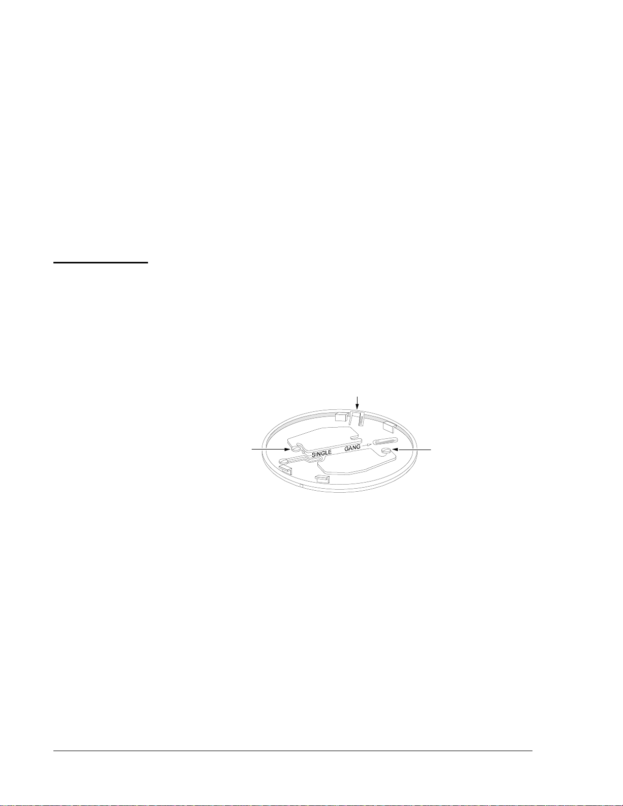
Tamper
Resistant Tab
mountbrk
To make detector tamper-proof,
break off tab extension at scribed line.
Figure 2: Detector Mounting Bracket
General
Information
Mounting

8 Conventional Products—2400AT and 2400AIT Direct 2-Wire Smoke Detector
National Fire Protection Agency (NFPA) 72-National Fire Alarm Code
defines the spacing requirements for smoke detectors. Typically, this is
30 feet when the detectors are installed on a smooth ceiling. However, all
installations must comply with NFPA 72-National Fire Alarm Code
and/or special requirements of the authority having jurisdiction. Where
conditions or response requirements vary, other spacing may apply.
All wiring must comply with the National Electrical Code, the applicable
local codes, and any special requirements of the authority having
jurisdiction, using the proper wire gauges. The conductors used to connect
smoke detectors to control panels and accessory devices should be color-
coded to reduce the likelihood of wiring errors. Improper connections can
prevent a system from responding properly in the event of a fire.
For Initiating Device Circuit (IDC) wiring (the wiring between
interconnected detectors as well as the control panel), it is recommended
that the wire be no smaller than No. 18 American Wire Gauge (AWG)
(1.0 square mm). However, the screws and clamping plate in the base can
accommodate wire sizes up to No. 12 AWG (3.3 square mm).
For best system performance, the power (+ and –) wires should be a
twisted pair and installed in a separate grounded conduit or shielded cable
to protect the IDC from extraneous electrical interference. If a cable shield
is provided, the shield connection to and from the detector must be made
continuous by using wire nuts, crimping, or soldering, as appropriate for a
reliable connection.
To make wire connections:
1. Strip about 3/8 inch insulation from the end of the wire.
2. Slide the bare end of the wire under the clamping plate.
3. Tighten the clamping plate screw.
Note: Do not loop the wire under the terminals.
The detectors are marked with a compatibility identifier located as the last
digit of a five digit code stamped on the back of the product. Connect
detectors only to compatible control units as indicated in the Device
Compatibility Technical Bulletin in the Fire Management Accessories
Manual (FAN 445).
Spacing
Wiring
Installation
Guidelines

Conventional Products—2400AT and 2400AIT Direct 2-Wire Smoke Detector 9
Figure 3: Wiring Diagram for the 2400AT Detector
with 2-Wire Control Panel
Figure 4: Wiring Diagram for the 2400AIT Detector
with Isolated Thermal and 2-Wire Panels
!
WARNING: Shock hazard. Disable the power IDCs before
installing detectors.
1. Wire each detector following installation guidelines.
2. Line up arrows on the detector with arrows on the mounting bracket.
3. Turn the detector clockwise until it clicks into place.
4. Enable the tamper-proof feature. For instructions see the
Tamper-Proof Feature section of this technical bulletin.
Remote
Annunciator
smkwire3
2
1
3
UL Listed
2-Wire
Panel
Remote
Annunciator
21
3
Panel
MF GRS
Su
g
g
ested
End-of-Line
(
EOL
)
Resistor
Remote
Annunciator
smkwire4
2
1
3
Remote
Annunciator 2
1
3
Panel.....
MF GRS.....
Su
g
g
ested.....
EOL.....
Resistor.....
UL Listed
2-Wire
Panel
UL Listed
2-Wire
Panel
4545Panel.....
MF GRS.....
Su
g
g
ested.....
EOL.....
Resistor.....
Isolated Heat Detection Loop
Smoke Detector Loop
Installation
10 Conventional Products—2400AT and 2400AIT Direct 2-Wire Smoke Detector
5. After all detectors have been installed, apply power to the control unit.
6. Test the detector as described in the Testing section of this
technical bulletin.
7. Reset the detector at the system control panel.
8. Notify the proper authorities that the system is in operation.
Dust covers must be removed before the smoke detectors can sense smoke.
Dust covers provide limited protection against airborne dust particles
during shipping. Remove detectors before beginning remodeling or heavy
construction.
The tamper-proof tab in the detector mounting bracket can make the
detector tamper-proof by using a pocket screwdriver, or similar tool, to
detach the detector from the bracket.
To make the detector tamper-proof:
1. Use needle-nose pliers to break the smaller tab at the scribed line on
the tamper-proof tab (Figure 5).
Tamper-Proof
Slot
dirwirtm
Mountin
g
Bracket
Mountin
g
Screw
Mountin
g
.....
Screw.....
Figure 5: Enabling the Tamper-Proof Feature
To remove a detector from the bracket after it has been made
tamper-proof:
1. Use a pocket screwdriver, or other similar tool, to depress the
tamper-proof tab in the slot on the mounting bracket.
2. Rotate the detector counterclockwise.
The tamper-proof feature may be defeated by breaking and removing
the plastic lever from the base. However, this prevents using the
feature again.
Limiting
Exposure to Dust
Tamper-Proof
Feature

Conventional Products—2400AT and 2400AIT Direct 2-Wire Smoke Detector 11
Testing and Maintenance
Procedures
Before testing, notify the proper authorities that the smoke detector system
is undergoing maintenance and will be temporarily out of service. Disable
the zone or system undergoing maintenance to prevent unwanted alarms.
Before testing the detector, check for the presence of the flashing LED.
If it does not flash, power has been lost (check the wiring) or it is defective
(return for repair).
Detectors must be tested after installation and periodic maintenance.
After a detector is set into alarm by one of the following test methods, and
the alarm activating device is removed from the detector, the system
should be reset at the control panel before testing any additional detectors.
After all testing is complete, notify the proper authorities the system is
back in service.
Recessed Test Switch
1. Push and hold the recessed test switch with a 0.1 inch maximum
diameter tool, such as a pocket screwdriver.
2. The LED on the detector should light and report an alarm condition to
the control panel on the IDC within five seconds.
3. The piezo horn should also sound.
Calibrated Test Card (R59-18-00)
1. Remove the detector cover by placing a small-bladed screwdriver in
the side slot of the detector cover.
2. Twist it slightly until the cover can be turned counterclockwise for
removal.
3. Insert the NO ALARM end of the test card fully into the test slot
(Figure 7).
4. Slide it counterclockwise until it stops.
5. The detector should not alarm (wait at least 20 seconds).
6. Remove the test card by sliding it clockwise before removing.
7. Repeat with the ALARM end of the test card.
Testing
Testing the
2400AT and
2400AIT
12 Conventional Products—2400AT and 2400AIT Direct 2-Wire Smoke Detector
8. The LED should latch on within 20 seconds indicating alarm and
annunciating the panel.
9. Replace the cover by gently rotating it clockwise until it locks
in place.
Test Module (System Sensor Model No. MOD400R and MOD400)
The MOD400R and MOD400 is used with an analog or digital voltmeter
to check the detector sensitivity as described in the test module manual.
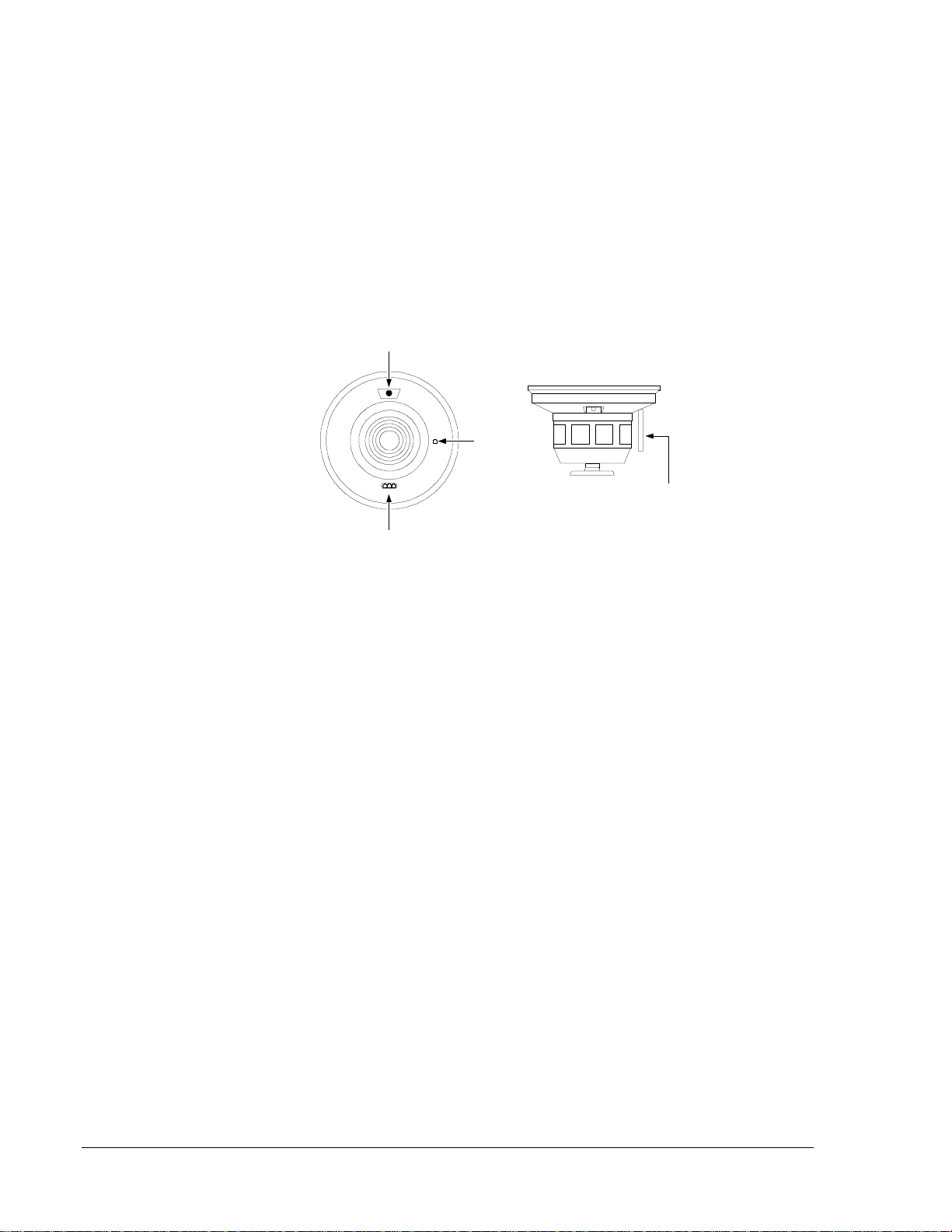
testswc3
Test Module
Socket
LED
Push recessed test switch
with a 0.1 inch Max. Diameter tool.
Recessed
TestSwitch
Figure 6: Bottom and Side Views
Showing Position of Test Switch
Aerosol Generator (Gemini 501)
1. Set the generator to represent 4%/ft to 5%/ft obscuration as described
in the aerosol generator manual.
2. Using the bowl-shaped applicator, apply aerosol until the unit alarms.
Direct Heat Method (Hair dryer of 1000-1500 watts)
1. Direct the heat toward the bimetallic collector.
2. Hold the heat source about 12 inches from the detector in order to
avoid damage to the plastic.
3. When the heat rises to greater than 135°F, the detector will latch
in alarm.
4. The detector will reset only after it has had sufficient time to cool and
the power source has been temporarily interrupted.
5. Both smoke and heat detection testing are recommended for verifying
system protection capability.
Detectors that fail these tests should be cleaned as described in the
Maintenance section of this technical bulletin and retested. If the detectors
still fail these tests, they should be returned for repair.

Conventional Products—2400AT and 2400AIT Direct 2-Wire Smoke Detector 13
Before cleaning, notify the proper authorities that the smoke detector
system is undergoing maintenance, and it will be temporarily out of
service. Disable the system undergoing maintenance to prevent unwanted
alarms. After maintenance is performed on a detector, it should be
functionally tested to assure proper operation.
1. Remove the detector cover by placing a small-bladed screwdriver in
the side slot of the detector cover.
2. Twist it until the cover can be turned counterclockwise for removal.
3. Vacuum the screen carefully without removing it.
If further cleaning is required, continue with Step 4, otherwise skip to
Step 9.
4. Remove the screen by pulling it straight out.
5. Vacuum the inside.
6. Clean the vaned chamber piece by vacuuming out dust and particles.
7. To replace the screen, orient it so that the arrow on top aligns with the
field test socket on the base of the detector.
8. Carefully push the screen onto the base making sure it fits tightly to
the chamber.
9. Replace the cover by gently rotating it clockwise until it locks
in place.
Maintenance

14 Conventional Products—2400AT and 2400AIT Direct 2-Wire Smoke Detector
covscr5
Removable
Head Cover
Cleanable Screen .....
(P/N RS24T) .....
Test Slot
Removal Slot
Figure 7: Removal of Cover and Screen for Cleaning

Conventional Products—2400AT and 2400AIT Direct 2-Wire Smoke Detector 15
This smoke detector is designed to activate and initiate emergency action,
but will do so only when it is used in conjunction with other equipment.
This detector is designed for installation in accordance with NFPA
Standards 71 and 72.
●Smoke detectors will not work without power. Alternating Current
(AC) or Direct Current (DC) powered smoke detectors will not work
if the power supply is cut off for any reason.
●Smoke detectors will not sense fires that start where smoke does not
reach the detectors. Smoke from fires in chimneys, in walls, on roofs,
or on the other side of closed doors may not reach the smoke detector
and alarm it.
●A detector may not detect a fire developing on another level of a
building. For this reason, detectors should be located on every level
of a building.
●Smoke detectors have sensing limitations. Ionization detectors offer a
broad range fire-sensing capability, but they are better at detecting
fast, flaming fires than slow, smoldering fires. Photoelectronic
detectors sense smoldering fires better than flaming fires. Because
fires develop in different ways, and are often unpredictable in their
growth, neither type of detector is always best, and a given detector
may not always provide warning of a fire. In general, detectors
cannot be expected to provide warnings for fires resulting from
inadequate fire protection practices, violent explosions, escaping gas,
improper storage of flammable liquids like cleaning solvents, other
safety hazards, or arson.
This detector is UL Listed to operate in a maximum air velocity of
3000 ft./min. Air velocity, along with other factors, may affect
detector sensitivity. See the 1993 NFPA-72-National Fire Alarm
Code, Appendix B for information.
●Test your smoke detector system per NFPA-72-National Fire Alarm
Code, or codes and standards specific to the country of installation, at
least semiannually. Clean your smoke detectors regularly.
Limitations of
Smoke
Detectors

16 Conventional Products—2400AT and 2400AIT Direct 2-Wire Smoke Detector
The sounder in this detector may not operate if the power is cut off for any
reason.
●The sounder may not be heard. The loudness of the sounder meets or
exceeds current Underwriters Laboratories (UL) standards. However,
the sounder may not alert a sound sleeper, one who has recently used
drugs, or one who has been drinking alcoholic beverages. The
sounder may not be heard if it is placed in an area which is isolated by
a closed door, located on a different floor from the person in hazard,
or placed too far away to be heard over the ambient noise such as
traffic, air conditioners, machinery, or music appliances that may
prevent alert persons from hearing the alarm.
●The sounder may not be heard by persons who are hearing impaired.
Limitations of
Sounders
Controls Group FAN 408
507 E. Michigan Street Fire Initiating Devices and Notification Appliances Technical Manual
P.O. Box 423 Printed in U.S.A.
Milwaukee, WI 53201
This manual suits for next models
1
Table of contents
Other Metasys Smoke Alarm manuals


Popular Smoke Alarm manuals by other brands


Landmann
Landmann 3215GS Assembly and operation manual

NEAT Electronics
NEAT Electronics SMOKE user manual

Teletek electronics
Teletek electronics SensoMAG M4 Installation instruction

Bellman & Symfon
Bellman & Symfon VISIT BE1551 user manual

IKEA
IKEA VAKTA manual

olympia electronics
olympia electronics BSR-6057/A/MAR quick start guide