Oppermann Regelgeräte KRM User manual

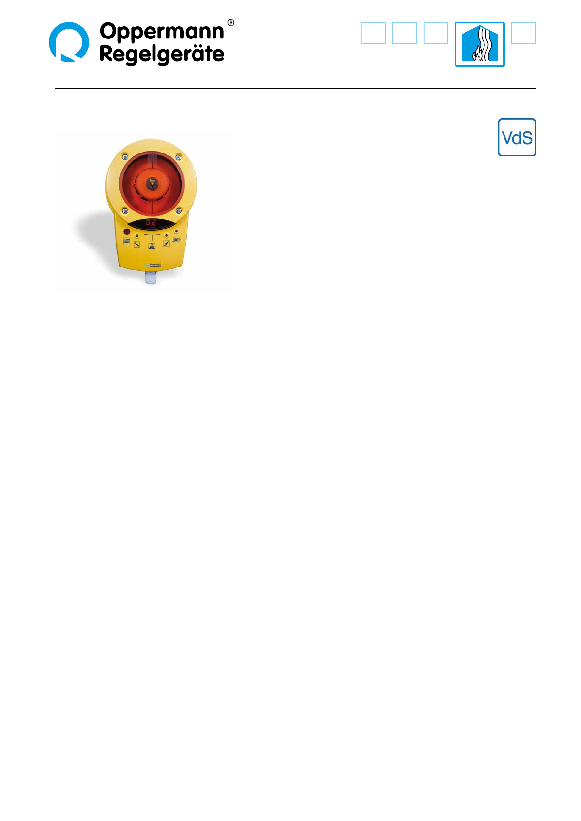
Duct Smoke Detector KRM®
Fire Protection | Data sheet No. 41300 | Version 06-2012 | 1 | 9
Technical Data
Sensor: Scattering RM 3.3 (ALK-E)
Supply voltage KRM-1: 230 V AC ± 10 %, 50/60 Hz
Supply voltage KRM-2/KRM-2-MOD:
24 V AC/DC +15 % / -10 %
Rated current: KRM-1: 30 mA
KRM-2/KRM-2-MOD: 120 mA
Relay outputs: oating
Alarm relay locked: 1 changeover contact, 8 A,
250 V AC or 24 V DC
1 NC, 8 A, 250 V AC or 24 V DC
Contamination relay:
1 NC contact, 6 A, 250 V AC or 24 V DC
Operating temperature:
-20 °C – +50 °C
Permissible ow:
1 – 20 m/s
Permissible humidity:
10 – 95 % non-condensing
Protection class:
IP54, IP65 with WDG
(water resistant housing)
Certication/approvals: VdS approval G210059
according to FprEN54-27
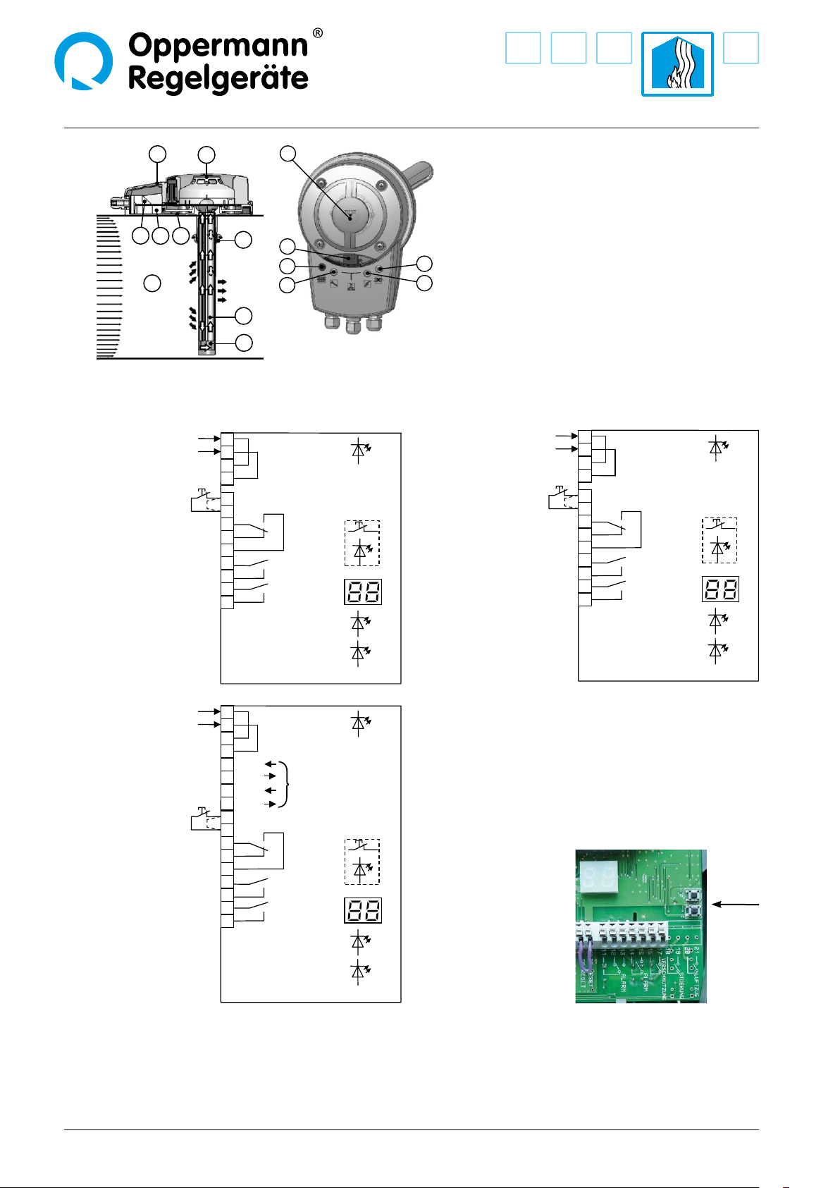
LED display:
% contamination level ashes
at > 70 %
LED in housing:
green operating
blue lack of air ow
yellow failure, electronics,
smoke detector defective,
low voltage
red smoke alarm, including
contamination > 99 %,
ashes at attempts to release
when the sensing chamber is
not empty
Adapter housing: ABS
Air measuring tube:
Aluminium / plastic
shortest length 160 mm
standard length 600 mm
Dimensions:
257 x 166 x 77 mm (L x W x H)
Screw connection:
3 x M16
• VdS certication (G210059)
• Patented single tube air sampling system
• Contamination display in %
and signalling at 100 %
• Electronic air ow control
• Externally operable reset button in the
housing
• Remote reset option via terminals
• Long service life, low contamination
• Modbus interface (KRM-2-MOD only)
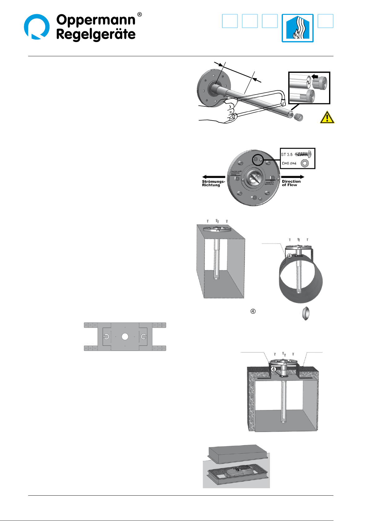
Accessories
Mounting bracket: KS (for insulated / circular ducts)
KS-WDG (for insulated / circular ducts in
combination with WDG)
Housing: WDG – waterresistant housing for
outdoor installation and increasing
protection class to IP65
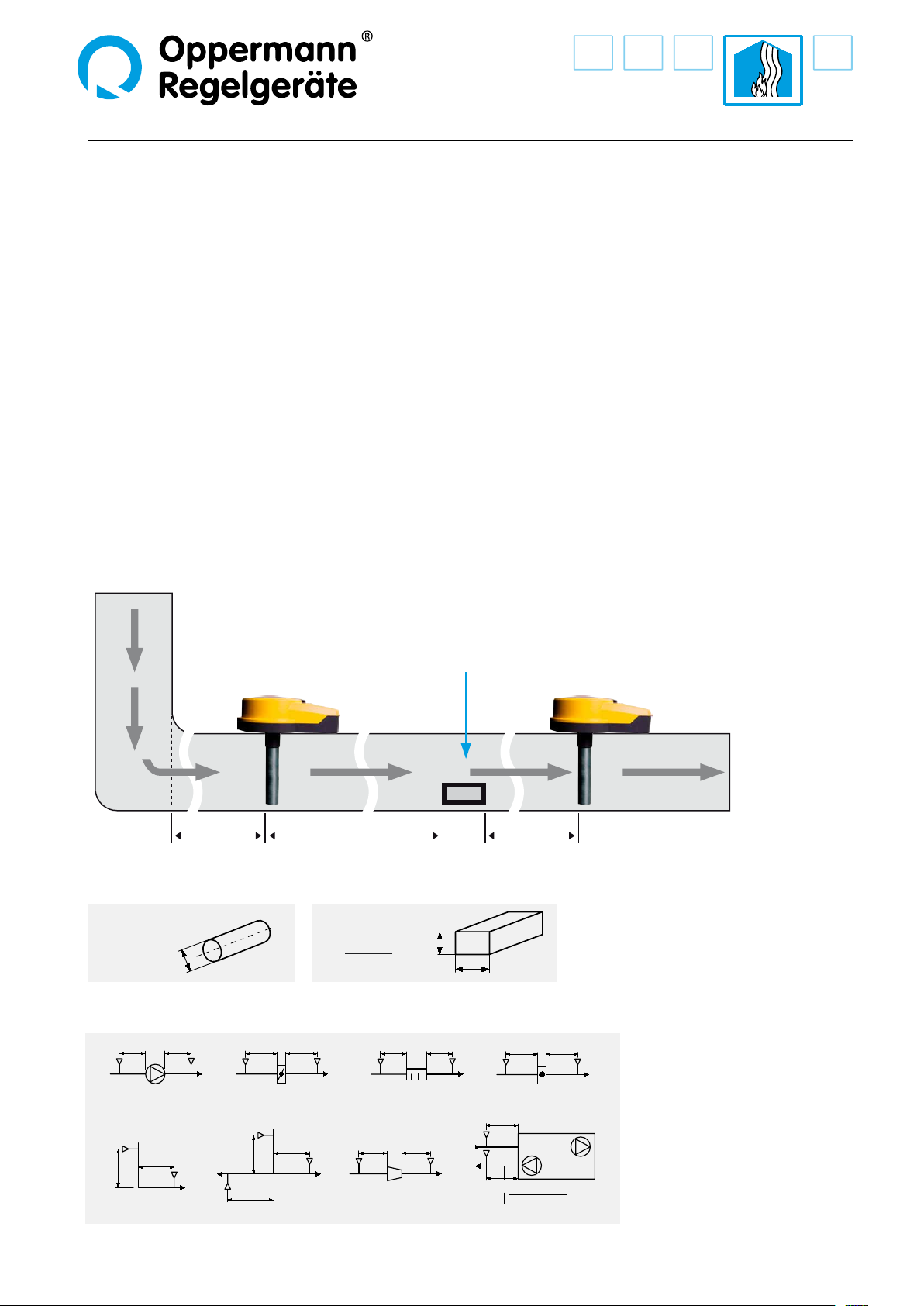
Function
The KRM duct smoke detector is designed for smoke detection in
ventilation ducts. It constitutes a combination of a smoke detec-
tor with an adapter system, whose measuring tube and housing
have been specially adapted for optimal air ow through the
smoke detector.
The multi-chamber measuring tube in the air duct transports the
air within the air duct along the entire length of the tube, through
the sensing chamber and back into the air duct. Upon detection
of smoke, the sensor reacts immediately and triggers an alarm.
Over time, the sensor becomes contaminated. Because of alarm
threshold tracking, the sensitivity up to total pollution remains
the same. From 70 % contamination upwards, the sensor is trig-
gered and indicates this by ashing. If the sensor is not replaced
the smoke alarm is triggered at 99 % contamination. The contami-
nation level is indicated in a two-line LED display; at > 70 % it
ashes.
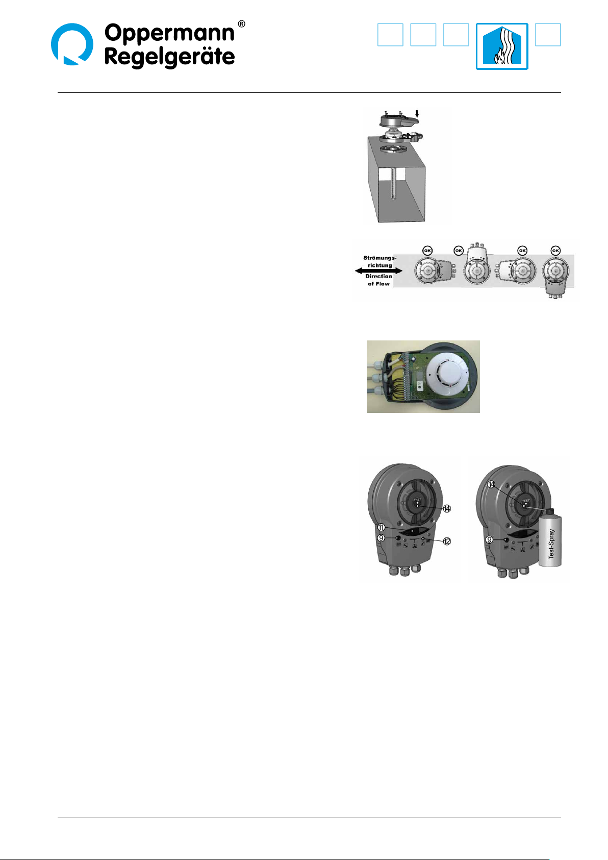
To verify operability, the device is equipped with electronic air
ow monitoring, which lights a blue LED at < 1 m/s. The failure
LED illuminates when the smoke sensor or the electronics are
defective, and in the absence of a smoke detector.
The smoke alarm must be released with the reset button.
A functionality test is also possible with the same button.
The operation functions like a smoke alarm.
Furthermore, the same function takes place on restart or when
the bridge circuit between terminals 9 and 10 is opened (remote
release).

Duct Smoke Detector KRM
2 | 9 | Fire Protection | Data sheet No. 41300 | Version 06-2012
Power supply
230 V AC
Test/Reset
(NC contact)
Power supply
24 V AC / DC
Test/Reset
(NC contact)
Power supply
24 V AC / DC
Test/Reset
(NC contact)
Contact depictions are with
the power o (alarm)
KRM-2, 24 VKRM-1, 230 V
KRM-2-MOD, 24 V
9
10
11
12
13
14
15
green
16
17
yellow
blue
Smoke alarm
Smoke alarm
Service signal
Contamination
red
Test/Reset
3
4
Power supply
230 V AC
1
2
KRM-1
9
10
11
12
13
14
15
green
16
17
yellow
blue
Smoke alarm
Smoke alarm
Service signal
Contamination
red
Test/Reset
3
4
Power supply
230 V AC
1
2
KRM-2
Electrical connection
10
1
2
3
4
5
6
7
8
9
11
12
13
15 10
9
11
12
13
14 1 Adapter plate with gasket
2 Patented measuring tube (max. length 3 m)
3 End cap
4 Rubber bushing
(only for insulated or circular ducts)
5 Lower housing with seal
6 Electronics
7 Optical smoke sensor
8 Upper casing with seal
9 Red LED: alarm / reset button
10 Yellow LED: failure
11 LED display: % of sensor contamination
12 Green LED: in operation
13 Blue LED: air ow under 1 m / s
14 Opening for test gas
15 Air duct
Remote reset/test (terminal 9 +10): if bridge circuit is removed, a oating NC contact must be connected.
Notes: The oating switching contacts (terminals 11 – 17) are to be assigned as uniformly as possible to an installation category according
to EN 60730-1. These switching contacts are only to be used for 230 V AC or 24 V AC / DC, no combinations are permitted unless at least one
contact between the potentials remains unassigned. A mixed connection of safety extra-low voltage (SELV) and low voltage must not occur.
The assembly may only be operated on one mains phase. The voltage / safeguard activation is to be provided on site. KRM-1-xx
(230 V versions) with a fuse of 16 A; KRM-2-xx (24 V version) with 4 A.
9
10
11
12
13
14
15
green
16
17
yellow
blue
Smoke alarm
Bus B
Bus B
Bus A
Bus A
Smoke alarm
Service signal
Contamination
red
Test/Reset
3
4
5
6
7
8
Power supply
RS485 Modbus
(for information)
Power supply
24 V AC/DC
1
2
KRM-2-MOD
Programming the Bus address for the KRM-2-Mod:
Press buttons T3+T4 on the circuit board (to the right, next to the
display) at the same time, so that the display changes from con-
tamination level to show the bus address (the display will ash).
Press button T3 or T4 to adjust the desired address (1 – 99). The
last set bus address is automatically saved. The display resets auto-
matically after 3 seconds or by simultaneously pressing T3+T4.

Fire Protection | Data sheet No. 41300 | Version 06-2012 | 3 | 9
Duct Smoke Detector KRM
Display and operation for Duct Smoke Sensor KRM
LED Smoke alarm (red) LED Smoke alarm (red)
LED Failure (yellow) LED Power supply
(green)
LED Alarm (red) and
Alarm / reset button
Failure reset:
Briey press button and release
Alarm reset:
Press button for at least 2 seconds
until the red LED goes out
Display indicator
(contamination in % or status)
LED Air ow (blue)
lights up when there is insucient ow
Display Meaning Comments
Start / calibration
Shortly after starting the software version is displayed (4 digits),
e. g. 00 then 20 = Software 0020
Thereafter, the rotating segment display follows at startup or after a power failure.
00 – 99
Contamination
in % Flashes starting at 70 %; at 99 % with display LED alarm.
Failure
e.g. Missing smoke detector, disrupted communication with the smoke detector,
processor failure.
Failure LED & alarm LED light up at the same time (not on the DIBt version).
Troubleshooting: Change the detector and conrm by pressing the alarm / reset button.
+
all LEDs on the
circuit board
light up
Conrmation
reset / new start
If alarm / reset button is pressed for more than 8 seconds, or if bridge circuit / terminal
9 / 10 is open (missing bridge circuit or remote reset). Display goes out after releasing the
alarm / reset button or closing the bridge circuit between terminal 9 + 10.
00 – 99
ashing BUS address Display only with MOD versions after pressing the address buttons T3 / T4 directly on the
circuit board.

Duct Smoke Detector KRM
4 | 9 | Fire Protection | Data sheet No. 41300 | Version 06-2012
Behavior of the alarm relay and fault relay and displays, plus reset options
Installation instructions and positioning
The KRM is to be positioned in accordance with the current
local state regulations on ventilation systems. Reliable smoke
detection must be guaranteed. Depending on the cross section
of the ventilation duct the air collecting tube may be cut to a
length of 160 mm. This minimum length of 160 mm must not
be undercut. This way, up to <100 mm ø can be monitored in
conjunction with the KS mounting bracket. With respect to the
maximum width/ maximum height/ maximum diameter of the
air ventilation ducts to be monitored with the 600 mm long
standard air collecting tube, there are no limitations according to
the VdS approval / DIBt certication. The airow direction must
be observed during the installation of the air collecting adapter.
The air collecting tube may be mounted laterally below or above
the air duct – the location is arbitrary.
LEDs Meaning Comments
Alarm / reset
(red)
Smoke alarm
or failure
Reset after failure:
Briey press alarm / reset button. KRM immediately restarts.
Reset after alarm:
Press and hold the alarm / reset button for at least 2 seconds until the red alarm LED in the
button goes out. Do not release it until then. KRM will start again only after release. As long as
the alarm / reset LED ashes when the button is pressed, the smoke sensor is still lled with test
gas / test spray / smoke, and can not be reset. In that case blow the sensor out or wait.
Failure
(yellow)
Defective circuit
board or missing
smoke alarm
Check / replace circuit board or smoke detector RM 3.3 (ALK-E).
Smoke alarm
(2 x red)
Smoke alarm
or contamination
99 %
Red LEDs directly on the smoke detector RM 3.3 (ALK-E). LEDs permanently on until reset has
taken place.
Power
(green)
Supply voltage
is on Green LED lights up if supply voltage is on.
Air ow
(blue)
Air ow is too
low
Blue LED lights up when air ow is too low and air relay (only equipped on DIBt versions) drops
out. Check smoke detector position in the duct, check sampling tube (TurboTube) for contami-
nation / clean if necessary.
Valid with soft-
ware 0020 Smoke alarm Device failure / missing detector…
DIBt versions
KRM-1-DZ / KRM-2-DZ
KRM-2-DZ-MOD
KRM-1 / KRM-2
KRM-2-MOD
DIBt versions
KRM-1-DZ / KRM-2-DZ
KRM-2-DZ-MOD
KRM-1 / KRM-2
KRM-2-MOD
Alarm relay
11 / 12 / 13 Drops out Drops out Drops out Drops out
Relais Alarm
14 / 15 Drops out Drops out Drops out Drops out
LED
Alarm / Reset Lights up Lights up Lights up Lights up
Relay failure
18 / 19 Does not drop out ---------
Not equipped Drops out ---------
Not equipped
LED failure Does not light up Does not light up Lights up Lights up
Alarm reset or
failure reset
Not with power
interruption!
It is mandatory to use
the alarm button or ter-
minal 9 / 10 provided that
sensing chamber is free.
With power interruption,
alarm button or with
terminal 9 / 10 provided
that sensing chamber
is free.
Not with power
interruption!
It is mandatory to use
the alarm button or ter-
minal 9 / 10 provided that
sensing chamber is free +
disturbance has ceased.
With power interruption,
alarm button or with
terminal 9 / 10 provided
that sensing chamber
is free + disturbance has
ceased.

Fire Protection | Data sheet No. 41300 | Version 06-2012 | 5 | 9
Duct Smoke Detector KRM
In the ideal case, install the KRM when structurally possible,
where ow meters, etc. are normally attached, so there is a lami-
nar airow along the measuring tube. We recommend that the
KRM be tted and installed at the same distance from heating,
cooling and humidity devices as ow sensors. The distance of
the KRM to ttings, valves, lters, etc. in terms of ow direc-
tion should be 3 times, and in the diagonal direction 5 times
that of the cross-section, if this structurally possible. The KRM
including the air collecting tube may not be installed along the
longitudinal edges of ventilation ducts (corner area). The KRM
is to be installed so that the air collecting tube is constantly in
the air stream. In horizontal ventilation ducts the KRM including
air collecting tube should be installed in the upper third of the
ventilation ducts or at the top of the ventilation ducts, if this is
structurally possible.
When, for structural reasons, the recommended positioning is
not possible, the KRM is to be mounted so that, nonetheless, a
reliable smoke detection/ow is ensured. The blue LED “Airow”
may be used as an indicator of a sucient ow (the LED is o
with sucient ow).
Follow these instructions. All work (such as installation, electri-
cal connection, start-up, operation and maintenance), must
be carried out by suciently qualied craftsman. Current local
rules and regulations (e. g. building regulations, elecrical/VDE
guidelines, etc.) are to be observed. Installers and operators are
required to be adequately informed before operation. Read the
product description before device start-up. Make sure that the
product is fully suited to the respective applications. We assume
no liability for misprints and changes after printing. Compliance
with operating and installation instructions is also included
within the regulations of intended use. We assume no liability
for damages caused by improper use. Operating licenses and
guarantees and all warranty claims will be voided in the event
of unauthorized modications or any tampering with the
device.
Hydraulic diameter dh
Example of positioning
after the change of
air duct direction. (Recommendation)
Example of positioning
after air outlets. (Recommendation)
Air outlet
Where there are large temperature dierences,
outdoors for example, or in places that are
dependent on outside temperature (roof, attic),
the air duct smoke sensor has to be insulated.
For this Oppermann Regelgeräte provides
a special splash-proof housing (WDG).
5 dh
3 dh
5 dh
MIN 3xd hMIN 5xd hMIN 3xd hMIN 5xd hMIN 3xd hMIN 5xd hMIN 3xd hMIN 5xd h
KRMKRMKRMKRMKRMKRMKRMKRM
KRM
KRM
KRM KRM KRM
KRM
KRM
KRM
MIN 5xd h
MIN 3xd h
MIN 5xd h
MIN 5xd h
MIN 3xd h
MIN 3xd hMIN 5xd h
MIN 5xd h
MIN 3xd h
Exhaust air
Supply air
Ventilator Airap Muer Battery
Air duct device
Air duct narrowing/
Air duct enlargement
Air duct forking
Change in air
duct direction
dh
=2xHxW
H+W
H
W
Rectangular duct
dh
=D øD
Round duct
Example of positioning (Recommendation)

Duct Smoke Detector KRM
6 | 9 | Fire Protection | Data sheet No. 41300 | Version 06-2012
Installation
1.
Drill a hole 43 – 44 mm in diameter at the intended mounting location.
Note: Installation of the TurboTube measuring tube is possible either from
the top, bottom or side of the channel for all duct
cross-sections (for round ducts as well).
2.
• Determine how long the measuring tube must be.
• If necessary, shorten the tube. Minimum length 160 mm.
• Deburr the cutting face and put the end plug back on up
to the stop collar.
Note: Depending on delivery batch, either the transparent end caps
displayed here or black end caps with a slightly dierent geometry will be
included in the delivery.
3.
• Determine the direction of ow and t the adapter plate so that
the line on the adapter plate under the text ”Strömungsrichtung” is
parallel to the ow direction.
• Four self-tapping screws serve for attaching it to the sheet metal
duct (not included in delivery).
4. Installation on a rectangular air duct
• see picture at right
5. Installation on a circular air duct
• For mounting on a circular air duct use mounting bracket type KS
and the rubber bushing . Thanks to the bend
perforations they can be adapted to a round duct.
The type KS mounting
bracket is supplied at.
6. Installation on air ducts with insulation
• Use the rubber bushing and insert it into the ø 43 – 44 mm
open ing in the air duct.
• Install the mounting bracket.
• Insert the assembled adapter plate into the measuring tube by
sliding the measuring tube through the grommet, and screw the
adapter plate onto the mounting bracket using the 4 self-tapping
screws. Then the insulation can be installed.
7. Installation outdoors or in a cold environment
• As protection for smoke detectors which are exposed to the open
air or in a cold environment there is a special WDG type splash-proof
housing. This enclosure prevents the warm air in the smoke detector
duct from condensing.
The interior of the housing is insulated with
foam rubber.
min. 160 mm
Mounting
bracket
Rubber bushing
inner
Mounting bracket Insulation
outer
Attention: Operation without
end plug not permitted.

Fire Protection | Data sheet No. 41300 | Version 06-2012 | 7 | 9
Duct Smoke Detector KRM
8. Installing the housing with the sensor
• Attach the housing bottom part with the electronics and sensor to the
adapter plate. The housing can be attached at increments of 90°. The
direction of the housing has no eect on the measurement result. You
can align the housing with the sensor optimally.
• Check that the seals in the housing upper part are correctly positioned.
• By snapping on and tightening the upper housing and then rmly
pressing down on the arrow marked on the central cable area (to ensure
that the catch at the lower end of the housing snaps in correctly), the
mounting is complete.
• Wire the unit according to the applicable circuit diagram.
• Attention: wiring and electrical connections may only be carried out by
a qualied electrician.
• Make sure that all cables are connected by a properly qualied electri-
cian. The cable jacket for eld wire connecting must be done as near as
possible to the terminal block. For wires longer than 10 mm, the wire
must be xed by a cable clip near the terminal block or insulated in
pairs with a suitably protective tube.
9. Testing the duct smoke sensor
• After completing the installation work, doing proper wiring (please
note the separate data sheets / circuit diagrams) and applying power,
the duct smoke sensor is operational.
• The green LED (12) illuminates.
• By pressing the alarm / reset button (9), an initial simple functional
test can be made. All LEDs must light up and all the relays drop out.
The units connected to the relays are activated! The display (11)
indicates the current degree of sensor contamination. If the button
is released, all LEDs will go out except for LED (12) which shows the
supply voltage, and the relays activate.
• For testing the smoke sensor the housing must not be opened. It has
a self-closing test opening (14) in the center of the transparent cover.
Use Oppermann test gas spray. Insert the test spray‘s tube fully into
the test opening (appx. 1.5 mm deep) and release as much test gas
as needed until the smoke sensor activates. Please do not spray too
much, otherwise the smoke sensor may display a higher degree of
contamination at the next start / reset. The alarm / reset button lights
up, the relays drop out. The electronics are on alert and locked. To
release, the alarm / reset button must be pressed. At the time of the
reset, the sensor must be free of smoke and test gas. Should there
still be test gas in the chamber a higher degree of contamination will
appear. In this case, after some time perform a reset by disconnecting
from the power or by an external reset, or if necessary, remove the
housing cover and blow out the smoke detector.
10. Final review
• Are all screws tight?
• Is the adapter plate properly mounted for the
ow direction?
• Are all seals in the correct position?
• In operation, when air ow > 1 m / s the blue
LED may not light up.
Application example:

Duct Smoke Detector KRM
8 | 9 | Fire Protection | Data sheet No. 41300 | Version 06-2012
Caution voltage
Before working on equipment, turn voltage o
Please follow the instructions
Maintenance and repair
1. Instructions for operation and
maintenance
The operator is responsible for the safe function of the ventila-
tion system. He has to ensure that the smoke sensors are always
ready for operation and that they are maintained, including all
controlling components and systems. In order to ensure good
performance over a longer period of time the smoke alarms
must be tested at least once a year. Without maintenance,
and depending on environmental conditions, the sensor will
become dirty sooner or later, and after a certain time will trigger
an alarm, which is a false alarm.
All types will give a specic maintenance requirement
signal at a contamination level of 70 % (display ashes).
Targeted maintenance can be carried out since the smoke
detector is equipped with a 2-digit digital contamination
indicator. From a 70 % contamination level or higher the smoke
sensor must be changed. There is a contact available for this
“contamination” signal, and it should be connected to the
automation station.
2. Maintenance and repair work
Before starting with the maintenance work, the functional
integrity of the unit when it is exposed to smoke must be clari-
ed with the sta. If, due to operational specications short-
term shutdowns cannot be tolerated, measures must be taken
to prevent this; if necessary by placing a bridge over the alarm
contact, but remembering to remove it after completion of the
service work. After maintenance work, a complete functional-
ity test of all plant parts must be carried out. If defects have
appeared they must be removed immediately. A protocol must
be made after all maintenance work and the results are to be
written into the operation manual, which is to be signed by the
operator in charge.
Caution:
Before opening the housing, unlock all supply voltages – The
housing may only be opened by a qualied electrician. Supply
and switching voltages must be observed.
Please note the symbols on the device:
The following work is required and can only be carried out by us
or by our authorized experts:
1. The smoke detector is accessible by removing the cover.
2. By turning the white detector on the base by about 20° to
the left the sensor can be unscrewed, and dirt and dust can
be removed. If it is too dirty (indicator >70 %), the sensor
must be removed and exchanged for a new sensor.
3. Also to be cleaned:
• the cover
• the TurboTube measuring tube
• the inner housing

Subject to change. Fire Protection | Data sheet No. 41300 | Version 06-2012 | 9 | 9
Duct Smoke Detector KRM
Oppermann Regelgeräte GmbH | Im Spitzhau 1 | D-70771 Leinfelden-Echterdingen
Telefon +49 711 72723560 | Telefax +49 711 7280527 | info@oppermann-regelgeraete.de | www.oppermann-regelgeraete.de
Dimensions
24
166
233
77
50
40
L= min. 160 mm
70
37.3
24
166
233
77
50
40
L= min. 160 mm
70
37.3
Dimensions in mm
4. Check the electrical connections, possibly tightening the
terminals. Make visual inspection and clean the electrical
circuit board if necessary, as well as the inner housing.
Check all seals.
5. Assemble all parts
6. Test system by triggering the smoke detector with
Oppermann Test Spray.
7. Check with the operator about the function of the down-
stream systems and components, such as:
• Turning o of fans
• Closing of aps
• Notication to the building automation system
• When checking network failure and recovery, does the
sensor return to its normal function and does it unlock
again from the state ”smoke alarm” and return to its normal
function when there is no longer any present?
• Release is possible by pressing the reset button (types:
KRM-1-DZ, KRM-2-DZ and KRM-2-DZ-MOD) or with
brief power interruptions (only for types KRM-1, KRM-2,
KRM-2-MOD)
• Release and approve for operation.

83
110
233
166
~260
4
44
Drilling template
Dimensions in mm
This manual suits for next models
6
Table of contents
Other Oppermann Regelgeräte Smoke Alarm manuals
Popular Smoke Alarm manuals by other brands

usi
usi USI-1213 manual

Gentex
Gentex 7109CS installation instructions

System Sensor
System Sensor D4120 Installation and maintenance instructions

Alecto
Alecto SA-19/5 manual

Ei Electronics
Ei Electronics Ei141 Ionisation installation instructions

System Sensor
System Sensor 1412A Installation and maintenance instructions