manuals.online logo
Brands
  1. Home
  2. •
  3. Brands
  4. •
  5. Oppermann Regelgeräte
  6. •
  7. Smoke Alarm
  8. •
  9. Oppermann Regelgeräte SOC-E3N User manual

Oppermann Regelgeräte SOC-E3N User manual

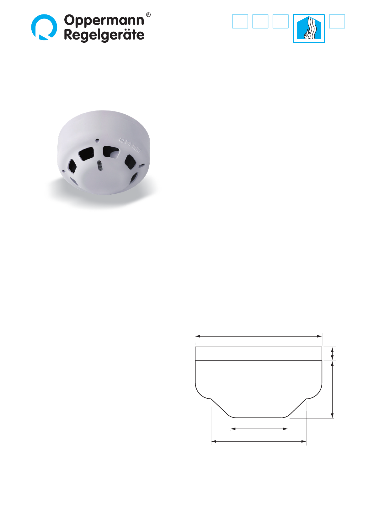
SOC-E3N Optical smoke detector with contamination indicator
and YBN-R/6 socket
Fire Protection | Data sheet No. 40105 | Version 08-2020 | 1| 3
Technical Data
Functional principle: Scattered light (Tyndall eect)
Certications:
LPCB (GB): certied iaw. EN 54-7
VdS (D) detector cavity: VDS G 217088
Power supply: 12 – 30 V DC
Operating current: approx. 0.04 mA
Alarm current: approx. 40 mA
Operating temperature: -10 – +50 °C
Max. humidity: 95 % RH, non-condensing
Detector housing: white polycarbonate
with insect guard
Socket: white polycarbonate
Weight: approx. 125 g
Contamination alarm: red LED ashing at 3s Intervals
Smoke alarm: red LED continuously lit
General information
The optical detector provides early warning for incipient res
with smoke, in particular smoldering res. The sensor cavity
houses a light source and receiver. Normally, the pulsating
light ray from the transmitter does not reach the receiver. If
smoke particles enter the sensor cavity, a portion of the light is
reected to the receiver resulting in an alarm trigger. A red LED
indicates the alarm. The alarm remains active until it is manually
reset at the control unit. In normal mode, the light transmitter
pulses every 8s to ensure a low monitoring current. The
detector design ensures enhanced resistance to interference
from air speeds, contamination, and EMC interference. The
detector module is mounted to the socket with a bayonet
lock and facilitates straightforward operation of the detector.
Fasten the smoke detector to the socket after removing the
plastic tab from the socket base. As contamination builds up,
the detector progressively approaches the alarm threshold. The
sensor is equipped with a contamination indicator to avoid false
alarms. When the contamination limit has been reached the
red LED starts ashing at 3-s intervals. Then the detector must
be cleaned by manufacturer or replaced. If this is not done,
the detector will indicate an alarm (red LED) after additional
contamination builds up.
Dimensions
Dimensions in mm
45
75
100
45
11
SOC-E3N Optical smoke detector with YBN-R/6 socket
2| 3| Fire Protection | Data sheet No. 40105 | Version 08-2020
Mounting and electrical connection
All work (such as installation, electrical connection, startup,
operation, and maintenance) must only be performed by
suciently qualied tradesmen. The respectively applicable
local rules and regulations (e.g. national building codes,
electrical/VDE regulations, etc.) must be observed. Installers
and operating entities are required to suciently familiarize
themselves before startup. Read the product description before
operating the equipment. Verify that the product can be used
for the relevant application without restrictions. We are not
liable for printing errors and changes after printing. Appropriate
use implies compliance with operating and installation
instructions. We are not liable for losses due to inappropriate
use. Unauthorized or inappropriate manipulations or
modications of the device render the operating permit,
the product warranty and warranty claims null and void.
Use dowels and screws to mount the socket on the ceiling
and route the cable through the center opening. The detector
locks onto the socket with a bayonet joint. Remove the plastic
tab from the bottom of the smoke detector before locking the
detector onto the socket. A tool with a diameter of ca. 3 mm
is required to dismount the detector.
Wiring diagram for operation with control unit ABAV-S3
Wiring the socket
12
5
6
3
412
5
6
3
412
5
6
3
4
14 13 12 11 10 98
ABAV S3
Control unit
Terminal
resistor
2.2 kOhm
Max. 30 detectors in total!
Optional
external LED indicator
(12 VDC, 20 mA)
Plastic tab on smoke detector
Unlocking the detector
Specications subject to change. Fire Protection | Data sheet No. 40105 | Version 08-2020 | 3| 3
SOC-E3N Optical smoke detector with YBN-R/6 socket
Oppermann Regelgeräte GmbH | Im Spitzhau 1 | 70771 Leinfelden-Echterdingen, Germany
Phone +49 711 72723560 | Fax +49 711 7280527 | info@oprg.de | www.oprg.de
Function check
The detector must be tested after installation and at least once
annually with suitable test spray (e.g. ASR-A10). The red LED
must light up; the control unit must switch to„Alarm“ and lock
out. The device is unlocked with the reset button on the
ABAV-S3 control unit or with a brief power supply interruption.
Maintenance
Contamination of the detector increases alarm sensitivity, which
can result in false alarms. This can be avoided by cleaning the
detector as soon as the red contamination indicator LED ashes.
Cleaning is possible by manufacturer only. The detector must be
replaced if it is completely contaminated.

Other Oppermann Regelgeräte Smoke Alarm manuals

Oppermann Regelgeräte DRM 3.3 User manual

Oppermann Regelgeräte

Oppermann Regelgeräte DRM 3.3 User manual

Oppermann Regelgeräte SOC-E3N User manual

Oppermann Regelgeräte

Oppermann Regelgeräte SOC-E3N User manual

Oppermann Regelgeräte KRM-X User manual

Oppermann Regelgeräte

Oppermann Regelgeräte KRM-X User manual

Oppermann Regelgeräte KRM User manual

Oppermann Regelgeräte

Oppermann Regelgeräte KRM User manual

Popular Smoke Alarm manuals by other brands

usi USI-1213 manual

usi

usi USI-1213 manual

Gentex 7109CS installation instructions

Gentex

Gentex 7109CS installation instructions

System Sensor D4120 Installation and maintenance instructions

System Sensor

System Sensor D4120 Installation and maintenance instructions

Alecto SA-19/5 manual

Alecto

Alecto SA-19/5 manual

Ei Electronics Ei141 Ionisation installation instructions

Ei Electronics

Ei Electronics Ei141 Ionisation installation instructions

System Sensor 1412A Installation and maintenance instructions

System Sensor

System Sensor 1412A Installation and maintenance instructions

SETRONIC VERONA BOOMERANG 5P70 quick start guide

SETRONIC VERONA

SETRONIC VERONA BOOMERANG 5P70 quick start guide

Edwards Signaling 517TCS Series installation instructions

Edwards Signaling

Edwards Signaling 517TCS Series installation instructions

Rielta Ladoga PD-RK installation guide

Rielta

Rielta Ladoga PD-RK installation guide

SB SB-SK540 quick start guide

SB

SB SB-SK540 quick start guide

Honeywell FMST FXV(E) Series installation manual

Honeywell

Honeywell FMST FXV(E) Series installation manual

Arton SPD-3.4 user manual

Arton

Arton SPD-3.4 user manual

Fire-Lite MS-9600 Supplement

Fire-Lite

Fire-Lite MS-9600 Supplement

Siterwell GS529 user manual

Siterwell

Siterwell GS529 user manual

Hekatron Genius H Mounting instructions

Hekatron

Hekatron Genius H Mounting instructions

Firephant SA800 user manual

Firephant

Firephant SA800 user manual

Firehawk FHB10W manual

Firehawk

Firehawk FHB10W manual

Cavius 2001-030 user guide

Cavius

Cavius 2001-030 user guide

manuals.online logo
manuals.online logoBrands
  • About & Mission
  • Contact us
  • Privacy Policy
  • Terms and Conditions

Copyright 2025 Manuals.Online. All Rights Reserved.