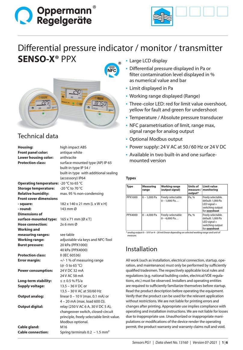
Oppermann Regelgeräte OPP-SENS P Series User manual

Sensors PG1 | Data sheet no. 13300 | Version 01-2020 | 1| 9
OPP-SENS® Pressure transmitter for water P-…
• Captive cover with 8-way positioning
• IP65 housing including seal
• Fast cable connection due to rotary lid and
spring terminals – tool-free
• 10 oset points: linear shift of characteristic
curve using the rotary switch
• 10 measurement ranges can be set using
the rotary switch
• 5P calibration: interpolation of the output
characteristics curve with 5 user-dened
interpolation points
Optional:
• Illuminated display, indicator and control
panel with capacitive keys
• BACnet / Modbus versions with 2 cable glands
Function
Measuring the pressure of uids in pipes and containers.
Installation
All work (such as assembly, electrical connection, commissio-
ning, operation and maintenance) must be carried out by sui-
tably qualied personnel. The current local rules and regulations
(e.g. building regulations, electrical/VDE guidelines etc.) should
be observed. Installers and operators are required to inform
themselves suciently before use. Read the product description
before operating. Make sure that the product is suitable for your
application. We accept no liability for misprints or changes after
publication. Intended use also includes compliance with the
operating and installation instructions. We assume no liability
for damage caused by improper use. Unauthorized or improper
alterations to this device will invalidate the type approval and
the warranty and guarantee claims.
Because of its minimal dimensions, the pressure transmitter
can be screwed almost anywhere via a sleeve into the medium,
if possible via a pressure gauge value with shut-o ventilation.
Attention to proper sealing should be ensured.
Technical data
Power Supply:
2-wire 15 – 35 V DC
3-wire / MOD / BAC 15 – 35 V DC or 15 – 30 V AC
Current draw: See table on page 3
Outputs:
2-wire 4 – 20 mA
(3.6 mA at fault)
3-wire 0 – 10 V or 4 – 20 mA
(-0.3 V or 3.6 mA at fault)
MOD/BAC digital
10 measurement 0 – 2 / 0 – 2.5 / 0 – 4 / 0 – 5 / 0 – 6 /
ranges:
0 – 8 / 0 – 10 / 0 – 12 / 0 – 14 / 0 – 16 bar*
*Factory setting
Tolerance: ±0.1 bar at 8 bar and 25°C
Long term stability: ±0.08 bar to EN60770-1
Max pressure: 40 bar
Perm.
ambient conditions: -20 – 70 °C, 0 – 95 % RH
(non-condensing)
Medium temperature: -25 – +85 °C
Insulation resistance: ≥ 100 M Ω, 20 °C, 500 V DC
Housing: base: PBT, color similar to RAL 7016
display: PC, transparent
front panel: PC, color similar to RAL 7016
ring: PBT, color similar to RAL 1003
Cable gland: M16, PA, color similar to RAL 7001
Terminals: Spring terminals 0.2 – 1.5 mm²
Connection thread: G½A
Wetted parts: process port: stainless steel 1.4305
sensor element: ceramic AI2O3
gasket: NBR

Pressure transmitter for water P-…
2| 9| Sensors PG1 | Data sheet no. 13300 | Version 01-2020
Important recommendations for installation
• The ceramic diaphragm can be ruptured by pressure con-
ditions or mechanical contact. HANDLE WITH CARE. Do not
attempt to test the sensor by pressing on the diaphragm.
• Short pressure pulses or surges (also called“hydro lock”)
are generated by a rapid change in the ow rate caused by
the operation of system components such as compressors,
pumps, pistons and valves. Hydro lock can reach pressure
levels that exceed the pressure rating of our pressure sensors
and damage the ceramic membrane.
• A pressure reducer (“snubber”) is a device to reduce the rate
of change of the ow system. The installation of a properly
sized snubber at the input of a pressure sensor, or nearby,
protects it from hydro lock damages. Snubbers are available
through plumbing and instrumentation dealers.
• When the sensor is screwed into a pipe system, back pressure
can cause damage to the ceramic membrane. Open nearby
valves to relieve any back pressure when screwing the sensor
into the pipe.
• While threading the sensor, if the nearby valves cannot be
opened in the pipe, a vent valve can be installed to prevent
over pressure.
• Make sure that there are no air bubbles in the pipe, especially
if a long tube is used to connect to the process pipe. Air
bubbles can cause measurement variations and errors. Main
valve closed.

Sensors PG1 | Data sheet no. 13300 | Version 01-2020 | 3| 9
Pressure transmitter for water P-…
Drawing
2x M16
Bus version
ø 89
110
Sizes in mm
Transmitter
Description Technical Data Type
Current transmitter (2-wire, 4 – 20 mA)
without display*
Power supply 15 – 35 V DC
Output 4 – 20 mA
P-TC-W16
Current transmitter (2-wire, 4 – 20 mA)
with display
Power supply 15 – 35 V DC
Output 4 – 20 mA
P-TC-W16-D
Current / voltage transmitter
(3-wire, 0 – 10 V/4 – 20 mA switchable)
without display*
Power supply 15 – 30 V AC/DC
Current draw 35 mA (24VAC) / 10 mA (24VDC)
Output 4 – 20 mA bzw. 0 – 10 V
P-T-W16
Current / voltage transmitter
(3-wire, 0 – 10 V/4 – 20 mA switchable)
with display
Power supply 15 – 30 V AC/DC
Current draw 100 mA (24VAC) / 30 mA (24VDC)
Output 4 – 20 mA bzw. 0 – 10 V
P-T-W16-D
Modbus transmitter (Modbus RTU)
without display*
Power supply 15 – 30 V AC/DC
Current draw 80 mA (24VAC) / 25 mA (24VDC)
P-MOD-W16
Modbus transmitter (Modbus RTU)
with display
Power supply 15 – 30 V AC/DC
Current draw 145 mA (24VAC) / 45 mA (24VDC)
P-MOD-W16-D
BACnet transmitter (MS/TP)
without display*
Power supply 15 – 30 V AC/DC
Current draw 80 mA (24VAC) / 25 mA (24VDC)
P-BAC-W16
BACnet transmitter (MS/TP)
with display
Power supply 15 – 30 V AC/DC
Current draw 145 mA (24VAC) / 45 mA (24VDC)
P-BAC-W16-D
* To program/assign addresses and 5P calibration, a display must be used at least once.
** Display on the 2-wire models are not illuminated.
43
G½A
13

Pressure transmitter for water P-…
4| 9| Sensors PG1 | Data sheet no. 13300 | Version 01-2020
Electrical connection/settings
Current transmitter with 5P calibration (2-wire, 4 – 20 mA)
2-wire variant (P-TC-W16):
Terminals
24 V 2 Supply (+) 24 V DC
out 3 Output pressure (4 – 20 mA)
SW1: Measurement range
Position 0 1 2 3 4 5 6 7 8 9
Range
[bar] 0 –2 0 –2.5 0 – 4 0 – 5 0 – 6 0 – 8 0 –10 0 –12 0 –14 0 –16
SW2: 10 oset points pressure
Position 0 1 2 3 4 5 6 7 8 9
Oset
[bar] 0 0.1 0.2 0.3 0.4 -0.5 -0.4 -0.3 -0.2 -0.1
Menu display
Valid from sensor rmware 0.27 and display rmware 0.56:
The device has got 3 hierarchical menu levels:
– main menu
– conguration menu (simple parameters)
– password level (complex parameters, 5P-calibration)
Use the and buttons to move through the menu.
In the main menu the following information is displayed:
Display Description
Prs bar
Pressure
Type
Hardware variant / sensor type
Ver Sen
Firmware version of the sensor
Ver Dis Firmware version of the display
By simultaneously pressing the two and buttons for about
4 seconds, the conguration menu is started. By pressing
the button the currently displayed value can be changed.
The variable value will ash, it is changed with the and
buttons. By pressing the button again, the entered value is
stored. The following data can be displayed or changed here:
Display Description
Contr.%
Display contrast (Default 50%)
Norm %
Simulation of analog output
e.g. 50 % = 12mA
Passwd Password entry„0000“*
Buttons and are used to navigate the parameter menu. By
pressing the button for approx. 4 seconds (or if no button is
pressed for approx. 1 minute), the device leaves the parameter
menu and returns to the configuration menu. By pressing
the button again for 4 seconds (or if no button is pressed
for approx. 1 minute), the device returns to the main menu.
* In older rmware versions, only the password„0815“ is accepted.

Sensors PG1 | Data sheet no. 13300 | Version 01-2020 | 5| 9
Pressure transmitter for water P-…
Electrical connection/settings
Current / voltage transmitter with 5P calibration
(3-wire, 0 – 10 V / 4 – 20 mA switchable)
3-wire variant (P-T-W16):
Terminals
0 V 1 Ground (-)
24 V 2 Supply (+) 24 V AC/DC
out 3 Output pressure
SW1: Measurement range
Position 0 1 2 3 4 5 6 7 8 9
Range
[bar] 0 –2 0 –2.5 0 – 4 0 – 5 0 – 6 0 – 8 0 –10 0 –12 0 –14 0 –16
SW2: 10 oset points pressure
Position 0 1 2 3 4 5 6 7 8 9
Oset
[bar] 0 0.1 0.2 0.3 0.4 -0.5 -0.4 -0.3 -0.2 -0.1
SW3 Position 1: ON = Analog output 0 – 10 V
OFF = Analog output 4 – 20 mA
Menu display
Valid from sensor rmware 0.27 and display rmware 0.56:
The device has got 3 hierarchical menu levels:
– main menu
– conguration menu (simple parameters)
– password level (complex parameters, 5P-calibration)
Use the and buttons to move through the menu.
In the main menu the following information is displayed:
Display Description
Prs bar
Pressure
Type
Hardware variant / sensor type
Ver Sen
Firmware version of the sensor
Ver Dis Firmware version of the display
By simultaneously pressing the two and buttons for about
4 seconds, the conguration menu is started. By pressing
the button the currently displayed value can be changed.
The variable value will ash, it is changed with the and
buttons. By pressing the button again, the entered value is
stored. The following data can be displayed or changed here:
Display Description
Time s
Illumination time of the display in seconds
(0 = light always on)
Contr.%
Display contrast (Default 50%)
Norm %
Simulation of analog output
e.g. 50 % = 5 V or 12mA
Passwd Password entry„0000“*
Buttons and are used to navigate the parameter menu. By
pressing the button for approx. 4 seconds (or if no button is
pressed for approx. 1 minute), the device leaves the parameter
menu and returns to the configuration menu. By pressing
the button again for 4 seconds (or if no button is pressed
for approx. 1 minute), the device returns to the main menu.
* In older rmware versions, only the password„0815“ is accepted.

Pressure transmitter for water P-…
6| 9| Sensors PG1 | Data sheet no. 13300 | Version 01-2020
Electrical connection / settings
Modbus transmitter with 5P calibration
Modbus variant (P-MOD-W16):
Terminals
0 V 1 Ground (-)
24 V 2 Supply (+) 24 V AC/DC
A 3 Modbus RS485A
B 4 Modbus RS485B
S 5 Screen
SW2: 10 oset points pressure
Position 0 1 2 3 4 5 6 7 8 9
Oset
[bar] 0 0.1 0.2 0.3 0.4 -0.5 -0.4 -0.3 -0.2 -0.1
SW3 Position 1: ON = 120 Ω terminating resistor
switched on
Note:
We recommend our parameter
programming tool PROG-MOD-01
to program Modbus parameters
quickly.
See data sheet 20914.
Menu display
Valid from sensor rmware 0.28 and display rmware 0.56:
The device has got 3 hierarchical menu levels:
– main menu
– conguration menu (simple parameters)
– password level (complex parameters, 5P-calibration)
Use the and buttons to move through the menu.
In the main menu the following information is displayed:
Display Description
Prs bar
Dierential pressure
MB Addr
Modbus address
Type
Hardware version/sensor type
Ver Sen
Firmware version of the sensor
Ver Dis
Firmware version of the display
By simultaneously pressing the two and buttons for about
4 seconds, the conguration menu is started. By pressing
the button the currently displayed value can be changed.
The variable value will ash, it is changed with the and
buttons. By pressing the button again, the entered value is
stored. The following data can be displayed or changed here:
Display Description
Time s
Illumination time of the display in seconds
(0 = illumination always on)
Contr.%
Display contrast (default: 50%)
Passwd Password entry„0000“*
After correctly entering the password (by pressing the button
jumps to the next position, using the buttons and changed
to the respective number) the following menu appears:
Display Description
MB Mode Modus (RTU or ASCII)
MB Baud baud rate (9.6, 19.2, 38.4 oder 56.0)
MB Pari Parity (Even, Odd or None)
MB Addr Modbus address
CHX1 bar
calibration -> see page 9...
CTY5 bar
Res. All Reset to default settings
Buttons and are used to navigate the parameter menu. By
pressing the button for approx. 4 seconds (or if no button is
pressed for approx. 1 minute), the device leaves the parameter
menu and returns to the configuration menu. By pressing
the button again for 4 seconds (or if no button is pressed
for approx. 1 minute), the device returns to the main menu.
* In older rmware versions, only the password„0815“ is accepted.

Sensors PG1 | Data sheet no. 13300 | Version 01-2020 | 7| 9
Pressure transmitter for water P-…
Bus settings
Modbus protocol
Mode: Sensor setting (default RTU) selectable RTU / ASCII
Baud rate: Sensor setting (default 9.6 (= 9600)) selectable 9.6 / 19.2 / 38.4 / 56.0
Parity: Sensor setting (default Even) selectable Even / Odd / None
Address: Sensor setting (default 1) selectable 1 to 127
CAUTION: Changes take eect immediately, without restarting the transmitter.
Data bits: 8 (in RTU mode); 7 (in ASCII mode)
Stop bits 1 (for parity Even / Odd); 2 (with no parity)
Function: 04 Read Input Registers (3x)
Register overview
Register PWM-Address Data type Measurement unit Description
0 (0x00)
30001
Signed 16 1/100 bar pressure
16 (0x10)
30017
Signed 16 0 = No sensor error
1 = Sensor error Error status
Request to the transmitter (RTU example)
Byte Byte 0 Byte 1 Byte 2 Byte 3 Byte 4 Byte 5 Byte 6 Byte 7
Description Address Function Start address Quantity register CRC
Example 01 04 0000 0001 …
Meaning Transmitter 1 Read input
registers Register 0
(PWM 30001) 1 Register Checksum
Response of the transmitter (RTU Example)
Byte 0 Byte 1 Byte 2 Byte 3 Byte 4 Byte 5 Byte 6
Description Address Function Quantity
data bytes Pressure
in 1/100 bar CRC
Example 01 04 02 002D …
Meaning Transmitter 1 Read input
registers 2
Data bytes 45 (= 0.45 bar) Checksum
Data type Signed 16

Pressure transmitter for water P-…
8| 9| Sensors PG1 | Data sheet no. 13300 | Version 01-2020
Electrical connection / settings
BACnet transmitter with 5P calibration
BACnet variant (P-BAC-W16):
Terminals
0 V 1 Ground (-)
24 V 2 Supply (+) 24 V AC/DC
A 3 BACnet (MS/TP), RS485A (Data+)
B 4 BACnet (MS/TP), RS485B (Data-)
S 5 Screen
SW2: 10-fach Oset Druck
Position 0 1 2 3 4 5 6 7 8 9
Oset
[bar] 0 0,1 0,2 0,3 0,4 -0,5 -0,4 -0,3 -0,2 -0,1
SW3 Position 1: ON = 120 Ω terminating resistor
switched on
Menu display
Valid from sensor rmware 0.30 and display rmware 0.56:
The device has got 3 hierarchical menu levels:
– main menu
– conguration menu (simple parameters)
– password level (complex parameters, 5P-calibration)
Use the and buttons to move through the menu.
In the main menu the following information is displayed:
Display Description
Prs bar
Dierential pressure
Bac MAC
BACnet MAC-Adresse
Type
Hardware version/sensor type
Ver Sen
Firmware version of the sensor
Ver Dis
Firmware version of the display
By simultaneously pressing the two and buttons for about
4 seconds, the conguration menu is started. By pressing
the button the currently displayed value can be changed.
The variable value will ash, it is changed with the and
buttons. By pressing the button again, the entered value is
stored. The following data can be displayed or changed here:
Display Description
Time s
Illumination time of the display in seconds
(0 = illumination always on)
Contr.%
Display contrast (default: 50%)
Passwd Password entry„0000“*
After correctly entering the password (by pressing the button
jumps to the next position, using the buttons and changed
to the respective number) the following menu appears:
Display Description
Bac Bd Baud rate (9.6 (Default),
19.2, 38.4, 57.6, 76.8, 115.2 or auto)
Bac MAC BACnet MAC address (1 to 127, Default 99)
CPX1 bar
calibration -> see page 9...
CPY5 bar
Res.All Reset to default settings
Buttons and are used to navigate the parameter menu. By
pressing the button for approx. 4 seconds (or if no button is
pressed for approx. 1 minute), the device leaves the parameter
menu and returns to the configuration menu. By pressing
the button again for 4 seconds (or if no button is pressed
for approx. 1 minute), the device returns to the main menu.
* In older rmware versions, only the password„0815“ is accepted.
The OPP-SENS_BACnet_Dokumentation (PICS, EPICS, EDE
and BTL certicate) can be found on our website
http://www.oprg.de/en/downloads/technical-information/
fully in one zip-le.

Specications subject to change. Sensors PG1 | Data sheet no. 13300 | Version 01-2020 | 9| 9
Oppermann Regelgeräte GmbH | Im Spitzhau 1 | 70771 Leinfelden-Echterdingen, Germany
Pressure transmitter for water P-…
Y (output value)
max
1
2
3
4
5
min
maxmin
X (sensor measuring value)
Y (output value)
max
1
2
3
4
5
min
maxmin
X (sensor measuring value)
Y (output value)
max
1
2
3
4
5
min
maxmin
X (sensor measuring value)
X (Sensor-Meßwert)
Y (Ausgabewert)
1
2
3
4
5
max
max
min
min
Original characteristic curve
End-values range
5P calibration
5P calibration
In all of the pressure transmitters 5-point calibration can be per-
formed. (optional display required).
Between the two end values 5 points can be adjusted as required
in X (sensor reading) and Y (output value). There is a linear inter-
polation between these points.
A reference point cannot be made through the measurement
limits in X and Y. The X values of the nodes must be numerically
in the order 1-2-3-4-5.
Non-monotonic values are ignored.
The following gures illustrate this:
Since the curve shown in the lower gure between the nodes
3 and 4 would be ambiguous (dashed line), the support
point 4 is ignored.
Should less than 5 calibration points be used, the unused
set points for X values should be set at the lower limit
(minimum setting) or the upper end value (maximum setting).
The corresponding Y value can be arbitrary.
In the conguration menu under
“
passwd
”
, enter the string
“
0000
”*
(by pressing the
button to jump to the next position,
with the
and
keys to change the respective number), the
calibration menu opens. Then additionally can be selected:
Menu option Reset to factory settings Default
CPX1 bar
1. Point Sensor reading
2.00
CPY1 bar
1. Point Output value
2.00
CPX2 bar
2. Point Sensor reading
4.00
CPY2 bar 2. Point Output
value
4.00
CPX3 bar 3. Point Sensor reading 6.00
CPY3 bar 3. Point Output
value
6.00
CPX4 bar 4. Point Sensor reading 8.00
CPY4 bar 4. Point Output
value
8.00
CPX5 bar 5. Point Sensor reading 12.00
CPY5 bar 5. Point Output
value
12.00
Res. All Reset to factory settings
To reset all values to the factory setting, select menu item“Res
All”and press the button for about 4 seconds. During the 4
seconds, the display will ash. Once the reset is complete, the
display shows“done”.
* In older rmware versions, only the password„0815“ is accepted.
This manual suits for next models
8
Table of contents
Other Oppermann Regelgeräte Transmitter manuals
Popular Transmitter manuals by other brands

4smarts
4smarts MEDIA&ASSIST quick guide

Extron electronics
Extron electronics DTP T USW 333 Setup guide

Risco
Risco WL T72C installation instructions

Rosemount
Rosemount 2051CF Series quick start guide

Siemens
Siemens SITRANS L Series Compact operating instructions

Silicon Laboratories
Silicon Laboratories Si4010 Series user guide