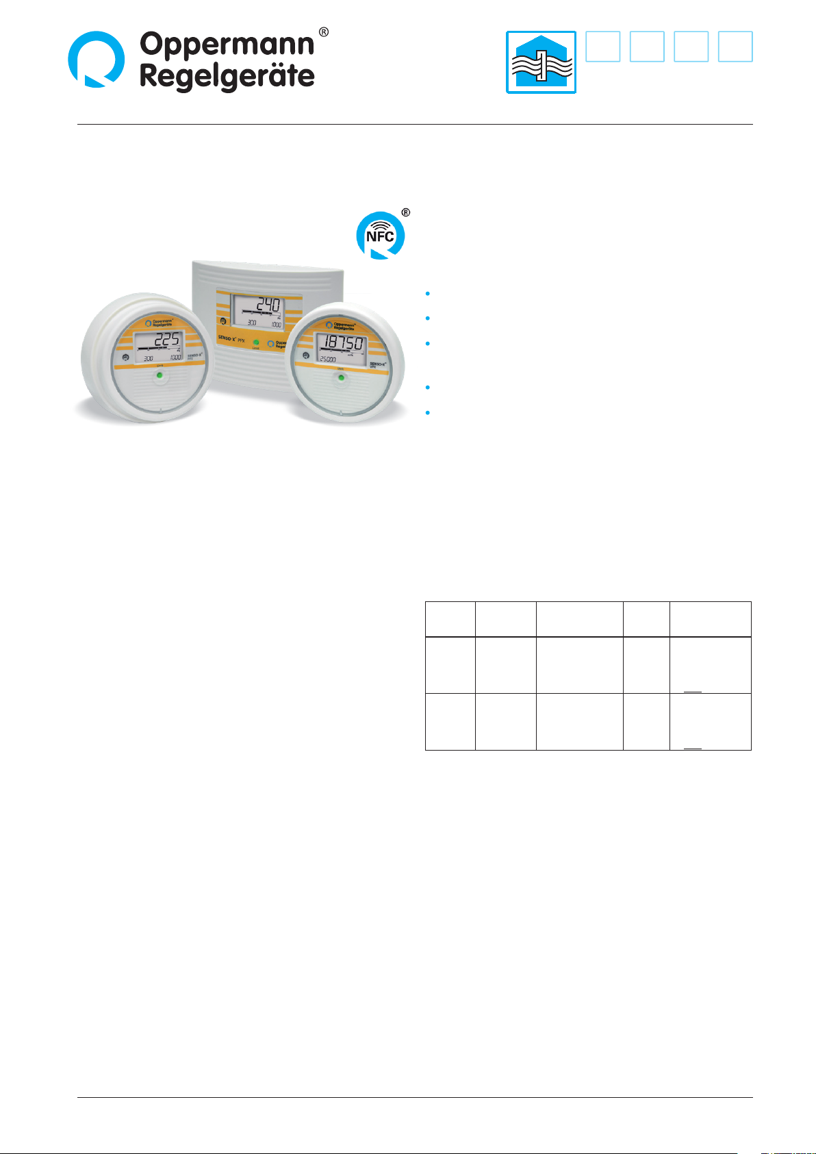
Dierential pressure indicator / monitor / transmitter SENSO-X® PPX
2| 6| Sensors PG1 | Data sheet No. 13160 | Version 07-2021
Built-in version
Mill a 115 mm Ø hole in the sandwich plate or cabinet door
and push the functional part through the opening from the
front. The mounting direction is indicated by an arrow pointing
upward on the back of the device. Screw the threaded rod
into the threaded sleeve with a screwdriver; slip the mounting
bracket over it and secure with a wing nut. When connecting
the pressure transfer hoses, care must be taken to comply with
the direction of the pressure (+/-). Finally, the front panel can be
snapped into place.
Surface-mounted housing
Screw the functional part onto a wall, duct or similar and then
connect it to the power and pneumatic lines. Then slip the ring
cover over the functional part and snap on the front cover.
Design
The built-in version of the SENSO-X®PPX consists of a round
section and a square or round front cover. The instrument is
optimized for installation in ventilation devices and control
cabinets. The two pressure test points, marked + (positive
pressure side) and - (negative pressure side), are sunk into the
housing on the back. In the middle is a threaded sleeve. Attach
the retaining bracket using the supplied threaded rod and wing
nut. The wing nut is secured against loosening. Two cable
breakthroughs are provided on the back of the housing. Two
M16 x 1.5 screw joints are included in the assembly kit. An
integrated O-ring serves to seal the functional part against the
mounting surface. The arrow on the back of the device points
upward in the correct mounting position.
The surface-mounted version of the SENSO-X®PPX consists of
a round functional part with three screw-on mounting brackets,
a ring cover and a snap-on front cover. The two measurement
connections, marked + (positive-pressure side) and – (negative-
pressure side), exit at the bottom. Exiting at the bottom are also
two strain relief elements.
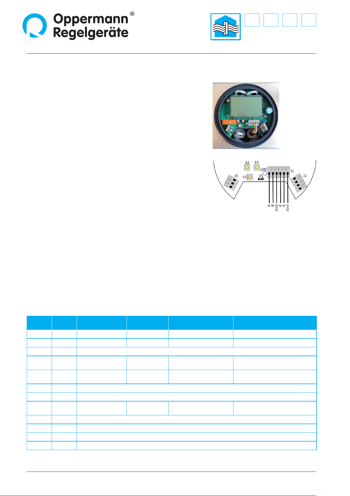
Built into the functional part in all versions, and visible from the
front, are an LCD display, an LED to indicate when limit values
are exceeded and 4 function keys.
After installation and conguration of the device, the front
cover is snapped onto the functional part. Due to 3 guided
notches this is only possible in the correct position. Removing
the front cover is done by pulling with both hands or by using
a screwdriver.
Operating principle
The measured dierential pressure is guided over the connecting
nipples with exible hoses onto the piezoelectric dierential
pressure sensor and electronically evaluated and displayed
on the LCD indicator. The limit can be programmed using a
key situated behind the front cover of the device. In the same
way, the value is passed on to the analog output, according to
the working range. The threshold set, monitors the available
measured values and reports an exceeded limit to the relay.
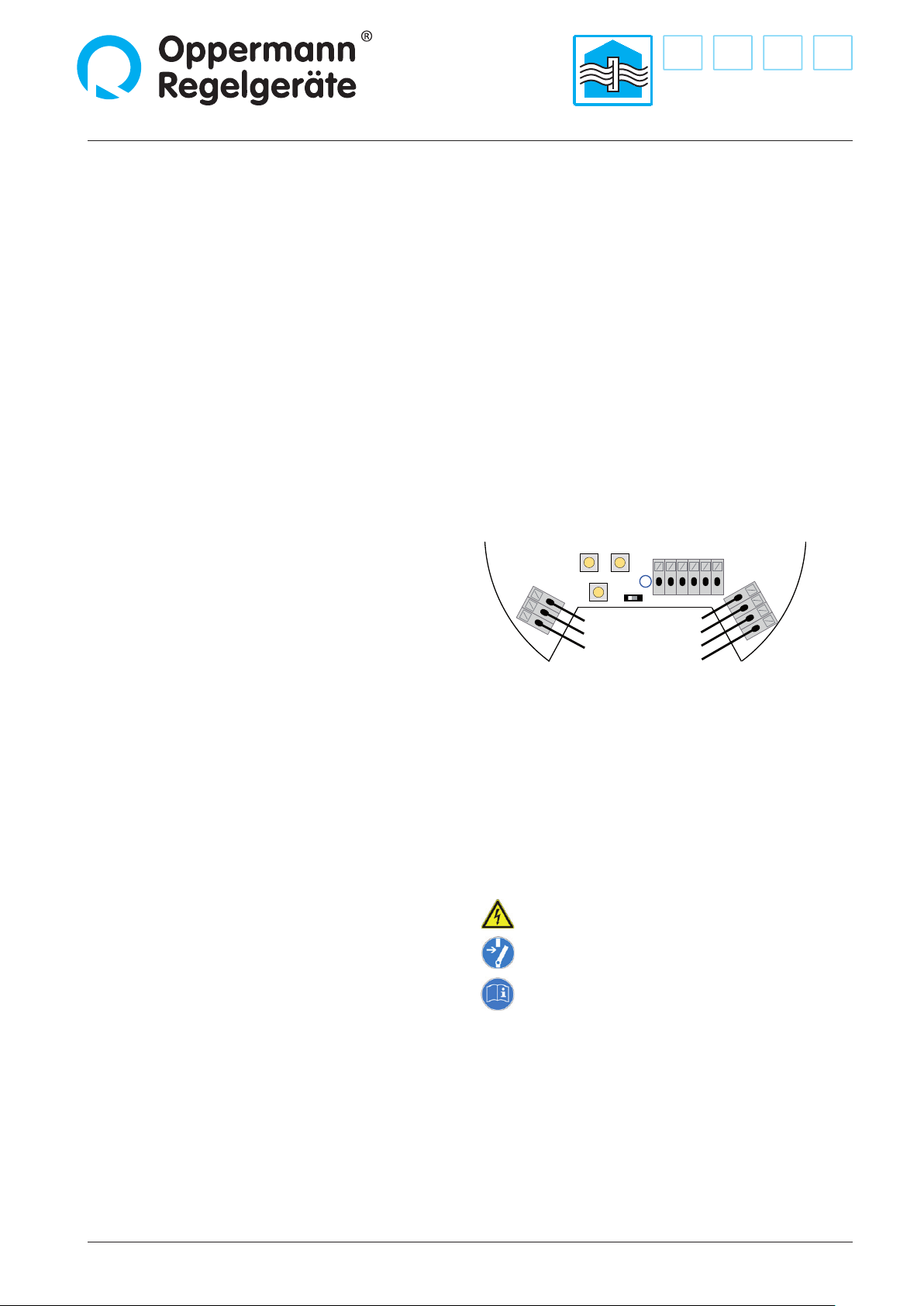
Activation and operation
Make all electrical connections before connecting the supply
voltage. Connect the 24 V supply voltage with the correct polarity
to start up the SENSO-X® PPX.
The device is ready for use immediately.
To set the parameters either take o the front panel and enter
the desired settings via the 3 keys or use the NFC tool (Windows
program for PCs: see Specication Sheet 13180; or Android App
for smartphones / tablets in the Google Play Store).
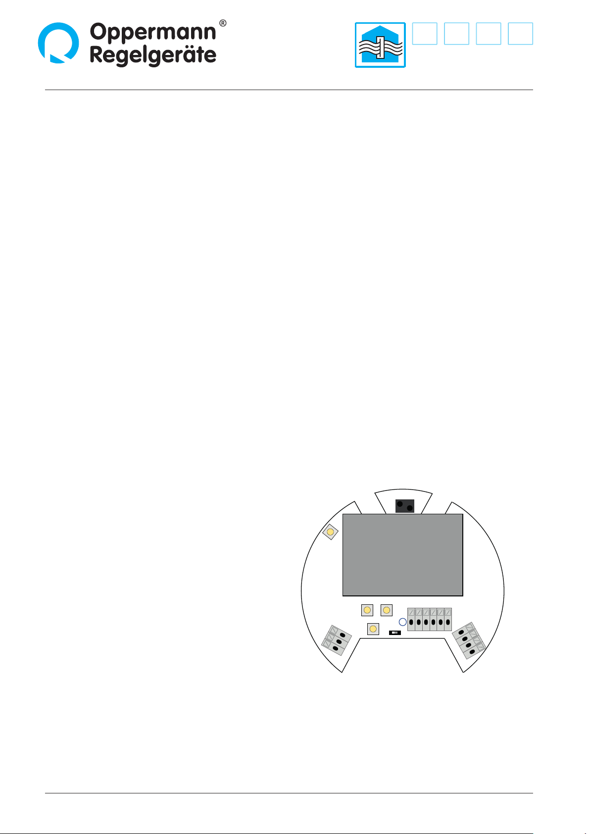
Setting display unit (dimension)
A brief push of the lower key (S1) in normal operation mode
switches the setting back and forth between Pa and %. If, e.g., %
is chosen as the unit of measure, the lter contamination level
is shown in numerals in % of the current limit value as well as
through an indicator bar.