manuals.online logo
Brands
  1. Home
  2. •
  3. Brands
  4. •
  5. OPTEX FA
  6. •
  7. Thermometer
  8. •
  9. OPTEX FA Thermo-Hunter PT-S80 User manual

OPTEX FA Thermo-Hunter PT-S80 User manual

THERMO-HUNTER PT-S80/U80
Portable Non-Contact Thermometer
Instruction Manual
Printed in JAPAN 1110-3 2015/8
OPTEX FA CO., LTD.
91 Chudoji-Awata-cho Shimogyo-ku Kyoto
600-8815 JAPAN
TEL: +81-75-325-1314 FAX: +81-75-325-2936
Ramco National - Optex FA Sensors
www.Optex-Ramco.com
Got Questions? 1-800-280-6933
2
introduction ・・・・・・・・・・・・・・・・・・・・・・・・・・・
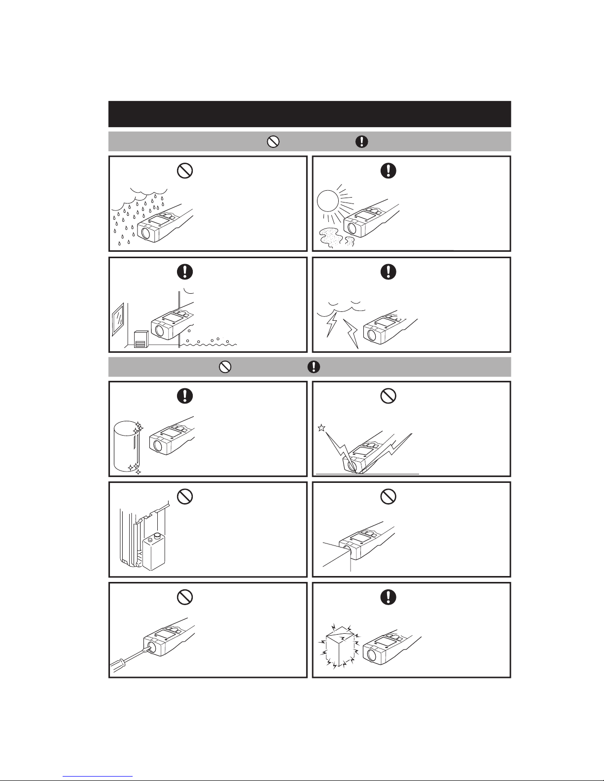
Safe Usage ・・・・・・・・・・・・・・・・・・・・・・・・・・・
Warnings & Caution on Environment and Usage ・・・・・・・・・・・
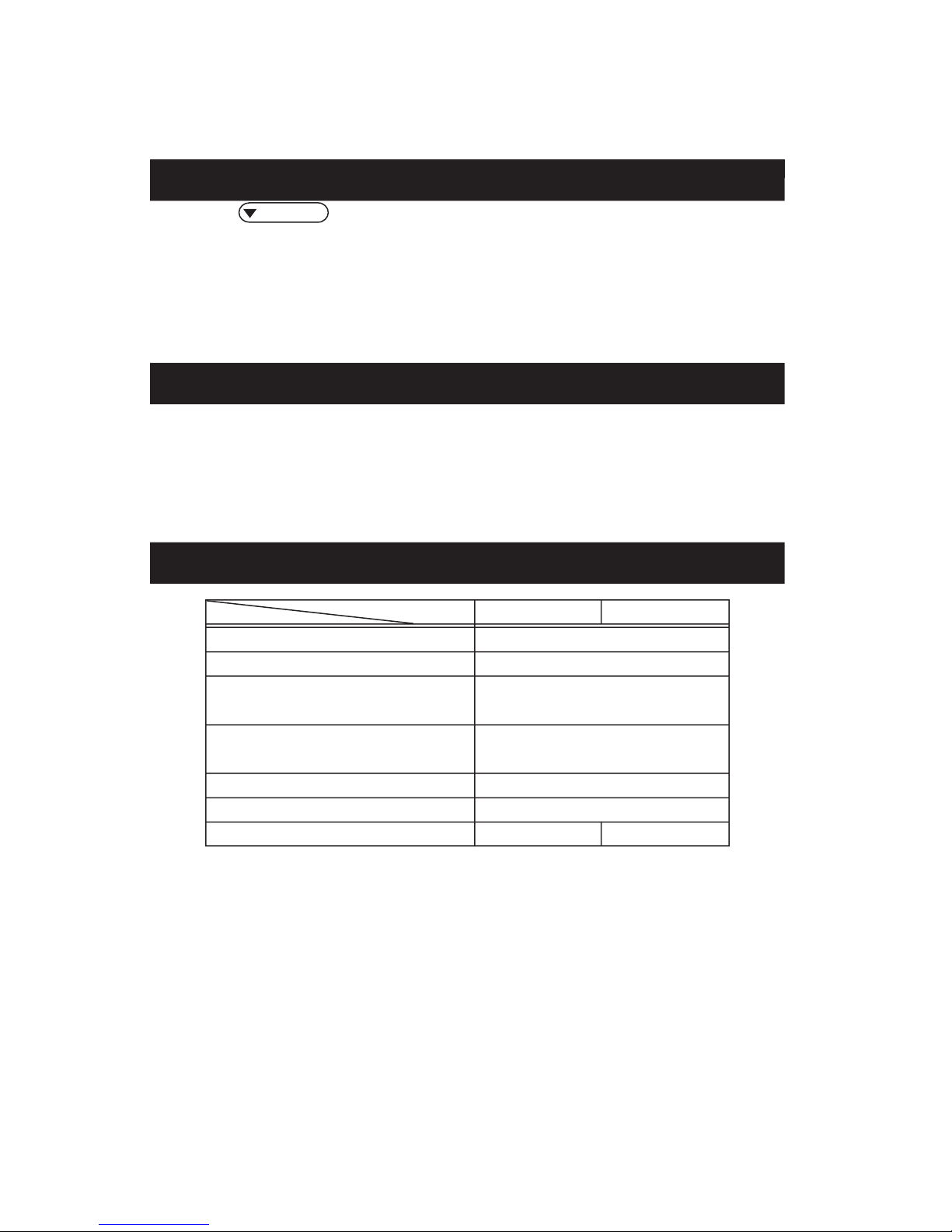
Specifications ・・・・・・・・・・・・・・・・・・・・・・・・・・
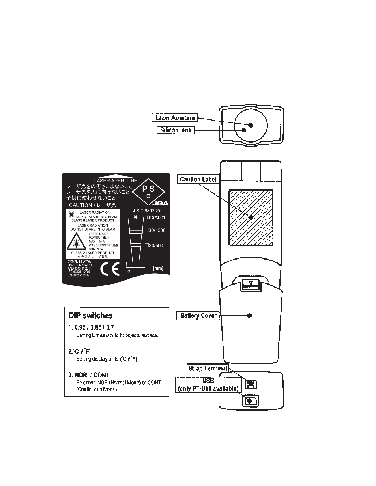
Name of Components ・・・・・・・・・・・・・・・・・・・・・・・
Operation ・・・・・・・・・・・・・・・・・・・・・・・・・・・・
Selection of Display Function ・・・・・・・・・・・・・・・・・・・
Selection of Temperature Unit ・・・・・・・・・・・・・・・・・・・
Default Value of Each Setting ・・・・・・・・・・・・・・・・・・・
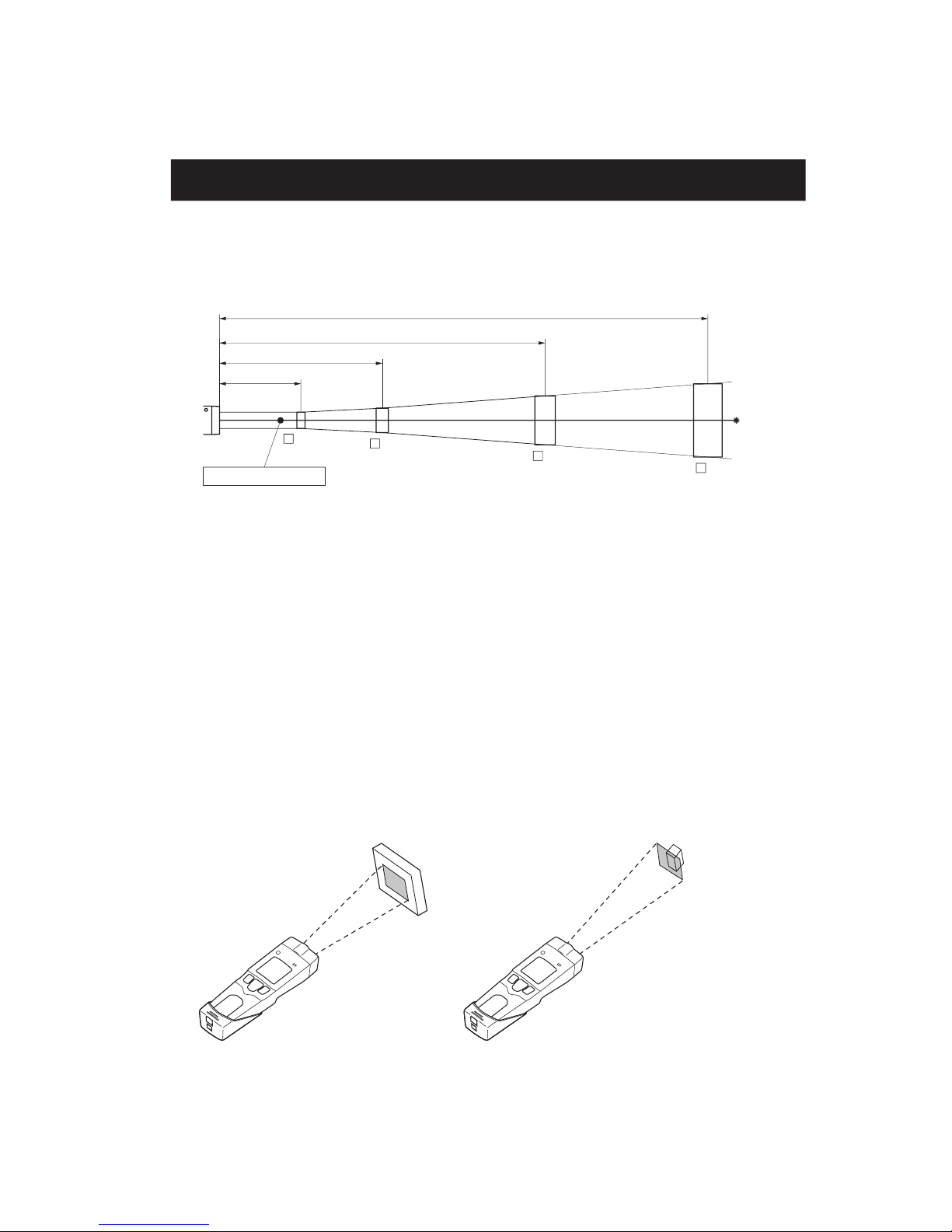
Field of View ・・・・・・・・・・・・・・・・・・・・・・・・・・・
Setting/Resetting the Upper/Lower Limit Temperature Alarm ・・・・・・
[PT-S80]
Recording Measured Temperature ・・・・・・・・・・・・・・・
•Record Measured Temperature(MEM.mode) ・・・・・・・・・・
•Call Temperature Record(CALL mode) ・・・・・・・・・・・・
Emissivity Setting ・・・・・・・・・・・・・・・・・・・・・・・
[PT-U80]
Date and Time Setting ・・・・・・・・・・・・・・・・・・・・・
Emissivity Setting ・・・・・・・・・・・・・・・・・・・・・・・
Recording Measured Temperature ・・・・・・・・・・・・・・・・
•Record Measured Temperature(MEM.mode) ・・・・・・・・・・
•Call Temperature Record(CALL mode) ・・・・・・・・・・・・
•Delete All the Temperature Records ・・・・・・・・・・・・・・
Continuous Measurement ・・・・・・・・・・・・・・・・・・・・
USB Connection ・・・・・・・・・・・・・・・・・・・・・・・・
Trouble Shooting ・・・・・・・・・・・・・・・・・・・・・・・・・
Maintenance Method/Batteries ・・・・・・・・・・・・・・・・・・・
2
3
4
5
6
8
9
9
9
10
11
12
13
13
13
13
14
15
17
18
18
18
19
19
20
21
22
Contents
Introduction
Conformance to EU Directives
・This in a class A product. In residential areas it may cause radio interference,
in which case the user may be required to take adequate measures to reduce
interference.
Thank you very much for purchasing OPTEX products. This device is a non-contact
thermometer to convert the infrared energy emitted from the surface of an object into
temperature. This thermometer measures the surface temperature of solid and liquid
without contacting them. The temperature of gas cannot be measured by this thermometer.
• Please make sure the model you purchased is the one you specified.
• Please read the manual thoroughly before using the THERMO-HUNTER
PT-S80/U80 for correct usage.
• After reading this manual,please retain it for future reference.
• OPTEX is not liable for any incidental or consequential damages or losses
including losses of data or changes of measurement,arising from
accident, misuse or abnormal conditions of operation or handling.
Ramco National - Optex FA Sensors
www.Optex-Ramco.com
Got Questions? 1-800-280-6933
3
This product is not a clinical thermometer
and therefore, can not be used for medi-
cal purposes.
Do not look into the laser beam, nor point
it directly at eyes. Even the reflection is
harmful. This laser may cause eye injury or
damage to your health.
Use of controls or adjustments or perfor-
mance of procedures other than those
specified herein may result in hazardous
radiation exposure.
Safe Usage
This instruction manual contains various warnings for your safety and proper usage to
avoid possible personal injury. Please be sure to heed the warnings and strictly follow
safety instructions.
This symbol signifies that improper usage may
result in injuries or damage.
!Caution:
! CAUTION
! CAUTION
! CAUTION
Ramco National - Optex FA Sensors
www.Optex-Ramco.com
Got Questions? 1-800-280-6933
4
Safe Usage
Environmental Warnings –– Warning –– Caution
_Environmental warnings/Cautions
KEEP THE THERMOMETER
AWAY FROM DROPPING WATER
AND DO NOT USE IN WATER.
This thermometer is not waterproof-
ing. Usage in such environments
may cause irreparable damages.
AVOID MEASURING SHINY OB-
JECTS.
KEEP THE THERMOMETER
AWAY FROM DIRECT SUNLIGHT,
DUST,HIGH TEMPERATURES
AND HIGH HUMIDITY DURING
USE AND STORAGE.
This may cause irreparable damage
or incorrect measurement.
DO NOT TOUCH THE FILTER.
Do not let a solid or shar p object
touch the filter and do not insert for-
eign objects into the filter.These may
cause incorrect measurement.
USE THE SPECIFIED BATTERIES.
Use of the other batteries may cause
irreparable damage or incorrect
measurement.
Usage Warnings –– Warning –– Caution
KEEP THE THERMOMETER
AWAY FROM SUDDEN CHANGE
IN AMBIENT TEMPERATURE.
Sudden temperature change may
cause incorrect measurement. Start
measurement when temperature
has become stable after leaving the
meter for a while.
KEEPTHETHERMOMETER AWAY
FROM STRONG ELECTROMAG-
NETIC SOURCES.
This may cause irreparable damage
or incorrect measurement.
Shiny objects reflect surrounding
infrared energy.
Therefore, it results in incorrect
measurement.
Usage in such environments may
cause irreparable damage or in-
correct measurement.
DO NOT DROP THIS THERMO-
METER NOR GIVE A STRONG
IMPACT TO IT, WHICH MAY
CAUSE IRREPARABLE DAMAGE
OR INCORRECT MEASUREMENT.
This product is a non-contact
thermometer. Touching high-
temperature object may cause
deformation of the meter, irreparable
damage or incorrect measurement.
DO NOT LET THE THERMO-
METER TOUCH THE OBJECT
THAT IS BEING MEASURED.
DO NOT BRING THE THERMO-
METER CLOSE TO ELECTRICALLY
CHARGED OBJECTS.
Ramco National - Optex FA Sensors
www.Optex-Ramco.com
Got Questions? 1-800-280-6933
5
Specifications
Accessories : AA battery
x
2pcs. (for checking operations), Instruction manual (this document)
exclusive protective case, USB cable (Only for PT-U80)
Optional : Blackbody tape
08U-TP08S-TPledoM
Measuring range - 30 to 600°C
(D:S=33:1)mm0001/03
weivfodleiF
sneliSscitpO
Sensing element Thermopile
mµ41ot8htgnelevaW
0%9/.ces5.0emitesnopseR
Accuracy (ε0.95) - 30.0 to 0°C : ± 3°C, 0.1 to 200°C : ± 2°C,
200 to 600°C : ±1% of reading value
eulavgnidaerfo°C1±ytilibataepeR
Display resolution - 30.0 to 199.9°C : 0.1°C, 200 to 600°C : 1°C
rekramresallaxaoCdohtemgnithgiS (Class 2)
sdnoces51emitDLOH
Continuous measurement mode
ON / OFF Selectable–
–
tuptuoBSU
Memory 1-point memory 35-point memory
High/Low Alarm LED/Buzzer Alarm LED/Buzzer ON/OFF Selectable
Emissivity (ε) Adjustment 0.95/0.85/0.70 Selectable εAdjustable
(0.30 to 1.20/0.01step)
Temperature unit °C / °F (Selectable)
NIM/XAM/RONnoitcnufyalpsiD
2pcs.×yrettaBAAylppusrewoP
)daolxamhtiW(sruoH51efilyrettaB
Ambient temperature 0 to 50°C
Ambient humidity 35% to 85%Rh (Without due condensation)
Storage temperature/humidity -10 ~ 60°C/35% to 85% Rh
EEET/SBAlairetaM
mm83×65×281=D×W×HnoisnemiD
s)eirettabgnidulcnI(g052.xorppAthgieW
complies with :
21 CFR 1040.10 AND 1040.11:2014
IEC 60825-1:2007
EN 60825-1:2007
EMC Directives 2014/30/EU
EN 61326-1:2013
※Specifications may change without prior notice.
Ramco National - Optex FA Sensors
www.Optex-Ramco.com
Got Questions? 1-800-280-6933
6
* There is no button to turn ON/OFF the supper supply.
Name of Components
Ramco National - Optex FA Sensors
www.Optex-Ramco.com
Got Questions? 1-800-280-6933
7
Ramco National - Optex FA Sensors
www.Optex-Ramco.com
Got Questions? 1-800-280-6933
8
Pressing the MEASURE button to turns
ON the power supply. A laser beam emit-
ted and the measurement starts.
In the Normal Measurement mode,
the units takes measurement while
MEASURE button is pressed.
Temperature can be measured while the MEASURE button is being pressed.
Set the batteries supplied as an accessory and operate the unit according to the following procedure.
1
Point the laser beam at a measurement
object and aim it at the center of the area to
be measured. For the distance from this
thermometer to the measuring object, re-
fer to page10.
2
When the MEASURE button is released,
the “MEAS” and laser beam symbols
go out and “HOLD”and “C (°F)”sym-
bols light up. After the last temperature
value is displayed for 15seconds (HOLD
mode), the power is automatically
turned OFF.
3
Operation
Ramco National - Optex FA Sensors
www.Optex-Ramco.com
Got Questions? 1-800-280-6933
9
Each time the /MAX/MINbutton is pressed, the display function is switched in order of NOR., MAX,
and MIN.
NOR. :“ε” is displayed at the bottom of LCD and the currently set emissivity is displayed on the sub-display.
MAX: “MAX” is displayed at the bottom of LCD and the maximum value during measurement is displayed
on the sub-display.
MIN: “MIN” is displayed at the bottom of LCD and the minimum value during measurement is displayed
on the sub-display.
Selection of display function
Default value for each setting (at the time of shipment)
PT-S80 PT-U80
Temperature unit °C
.RONnoitcnufyalpsiD
Maximum temperature alarm Temperature setting
: 600°C
Function : OFF
Minimum temperature alarm Temperature setting
: -30°C
Function : OFF
59.0
(ε)
ytivissimE
gnihtoNyromeM
Continuous measurement mode OFF–
Selection the temperature unit (°C or °F) referring to the “DIP switch setting” in page 7.
*The temperature unit is automatically switched with regard to the temperature displayed in the
HOLD mode, display function, setting values for upper/lower temperature alarms, and recorded data.
Selection of temperature unit
Ramco National - Optex FA Sensors
www.Optex-Ramco.com
Got Questions? 1-800-280-6933
10
For the non-contact thermometer (infrared thermometer), the field of view (spot size) is specified
depending on the distance from the thermometer to the measuring object as shown below. The temperature
value displayed is the average temperature within the spot size.To take an accurate measurement, check
the correlation between the size of object and the distance to it.
[Field of View]
*Remarks
ex.) The average temperature of surface of the square 90mm in diameter is measured at a distance
of 3000mm away from the measuring object.
*The laser beam points center of the field of view. The laser marker functions as a sighting method and
not a sensing element.
*It is possible to take temperatures with this thermometer at a distance of 1,000mm or more away from
the measuring object, unless there is any obstacle. However, please note that the measuring field of view
depends on measuring distance. This thermometer has an optical resolution of 33:1
[D(Distance to the measuring object):S(Spot size)].
[For Correct Measurement]
The optical resolution values stated in “Field of View” are at minimum 90% energy. The size of measuring
object should be sufficiently larger than the field of view (spot size) shown in the above illustration.
Please keep away from target as far as you can within spot ratio when you measure high temperature.
Sudden ambient temperature change may cause thermometer display value error. In this case, please
keep thermometer for a while until display value error may be corrected.
Field of View
500
1000
2000
20 30 60 90
D:S=33:1
[Unit : mm]
3000
OK NG
CORRECT
The measuring object is
bigger than the field of view.
INCORRECT
The measuring object is smaller than the
field of view. The temperature of background
influences the measuring value.
Optical Axis/Laser Marker
Ramco National - Optex FA Sensors
www.Optex-Ramco.com
Got Questions? 1-800-280-6933
11
1
Pressing the MEASURE button blinks
“ALM”. Then,“ON”or“OFF” (currently
set status) is displayed on the top of
LCD and “AL-H”is displayed on the
sub-display. (The High alarm is set up.)
2
Press the /MAX/MIN or
/MAX/MIN button to select ON or
OFF, and then press the MEASURE
button to confirm the setting.
When OFF is selected, the display
shifts to the setting for the lower limit
temperature alarm.
3
Press the SET button
while the power is ON.
The alarm temperature is displayed on
the top of LCD by selecting ON.
Press the /MAX/MIN or
/MAX/MIN button to select ON or
OFF, and then press the MEASURE
button to confirm the setting.
When the setting has been completed,
the display shifts to the setting for the
Low temperature alarm.
4
For the setting/resetting of the lower limit temperature alarm, the above steps can be
applied excluding that “AL-H”on the sub-display is changed to “AL-L” in step 2 and later.
When the lower limit setting has been completed, the mode is changed to HOLD.
When the upper and lower limit alarms are set, “HI”and “LO”lamps are lit on the display.
Note) Theupper limit temperature cannot be set to the value less than the setting for the
lower limit temperature alarm,andthe lowerlimit temperature cannot be set to the value
more than the setting for the upper limit temperaturealarm.
Setting/Resetting the High/Low Temperature Alarm
When the measured temperature of the object exceeds the High alarm value, the alarm LED blinks in red
and a buzzer (high tone) sounds. When it is below the Low alarm value, the alarm LED blinks in green and
a buzzer (low tone) sounds. The “High alarm” is set up first, and then the “Low alarm”.
Set up the alarms according to the following steps.
Pressing the SET button displays
“ALM” on the top of LCD.
(Regarding PT-U80, the display is
switched in order of “ALM”, “EMS”and
“TIME”each time the SET button is
pressed.)
SET
Ramco National - Optex FA Sensors
www.Optex-Ramco.com
Got Questions? 1-800-280-6933
12
PT-S80
■
P.13 Recording Measured Temperature
   □
Record Measured Temperature (MEM.Mode)
   □
Call
Temperature Record (CALL Mode)
■
P.13 Emissivity Setting
Ramco National - Optex FA Sensors
www.Optex-Ramco.com
Got Questions? 1-800-280-6933
13
[Record measured temperature/ MEM. mode]
After “CALL” is displayed on the sub-
display, “MEM”blinks on the display
and the temperature value that had
been displayed on the sub-display
when the /MEM./CAL button was
pressed starts to light up. Then the
value is stored in memory.
After the data is stored, the mode is
changed to HOLD.
1
1 Press this button for 2
seconds or more while
the power is ON.
[Call temperature record/CALL mode]
“CALL” is displayed on the sub-
display, and then the stored
temperature data displayed.
1
Press the MEASURE button to
terminate the CALL mode. Then, the
normal measurement mode i s
restored.
2
1 Press this button for
less than 2 seconds
while the power is ON.
Emissivity (ε) refers to the ratio of infrared energy emitted from all the object surfaces. All objects has their
own emissivity, which changes depending on the surface conditions and object temperature. This thermometer
has 3 fixed emissivities. Refer to the following examples.
0.95...Food, rubber, plastic, paintwork, etc.
0.85...Temperature of refrigerated food can be measured almost accurately.
0.70...Temperature of oxidized metal surfaces can be measured almost accurately.
The displayed temperature could differ from the actual temperature of objects that have different emissivity. In
such cases, regard the displayed temperature as a rough standard. When you wish to measure shiny metal
surfaces, put a piece of optional blackbody tape (ε=0.95) on the surface of the measured object.
Emissivity Setting
When the emissivity (0.95/0.85/0.7) is selected according to “DIP switch setting” in page 7, the
temperature value converted into the selected emissivity is displayed.
Recording Measured
Temperature
PT-S80 can store one (1) temperature measurement data.
Perform the following steps.
Ramco National - Optex FA Sensors
www.Optex-Ramco.com
Got Questions? 1-800-280-6933
14
PT-U80
■
P.15 Date and Time Setting
■
P.17 Emissivity Setting
■
P.18 Recording Measured Temperature
□
Record Measured Temperature (MEM.Mode)
□
Call Temperature Record (CALL Mode)
□
Delete All the Temperature Records
■
P.19 Continuous Measurement
■
P.20 USB Connection
Ramco National - Optex FA Sensors
www.Optex-Ramco.com
Got Questions? 1-800-280-6933
15
1
2
3Press the /MAX/MIN or
/MEM./CAL. button to adjust the
year. Then press the MEASURE
button to fix the setting.
After the setting, the set year blinks
on the LCD.
4
Date and Time Setting
5
To the page that follows
Press this button while
the power is ON.
SET
Date and time can be set in PT-U80.
Perform the following steps.
*The setting returns to the default if batteries are removed.
The LCD display is switched in order
of "ALM", "EMS" and "TIME" each
time the SET button is pressed.
Display "TIME" on the LCD.
After "TIME" blinks, "YEAR" blinks.
Then, the display is automatically
shifted to the state that "YEAR" lights
up and the dominical year blinks.
After the set year blinks, "date"
blinks, then the display is
automatically shifted to the state that
"date" lights up, the left 2 digits of the
clock (month) blinks and the right 2
digits (day) lights up.
The left 2 digits of the clock indicate a
"month" and the right 2 digits indicate
a "day".
Press the /MAX/MIN or
/MEM./CAL button to adjust the
month. Then press the MEASURE
button to fix the setting.
After the setting, the right 2 digits of
the clock blink. Then go to the "date"
setting.
Ramco National - Optex FA Sensors
www.Optex-Ramco.com
Got Questions? 1-800-280-6933
16
6
7
8
 
 
9
10
Press the /MAX/MIN or
/MEM./CAL. button to adjust the
month. Then press the MEASURE
button to fix the setting.
After the setting, the set month and
date blink on LCD.
After the set date blinks, "TIME"
blinks, and then the display is
changed to the state that the time
lights up, the left 2 digits of the clock
(hour) blinks and the right 2 digits
(minute) light up.
Press the /MAX/MIN or
/MEM.CAL. button to adjust the
hour. Then press the MEASURE
button to fix the setting.
After the setting, the right 2 digits of
the clock start to blink for the "minute"
setting.
 
Press the /MAX/MIN or
/MEM.CAL. button to adjust the
hour. Then press the MEASURE
button to fix the setting.
Then, the set time blinks on LCD.
After the set time blinks, "SEC" start
to blink and then the display is
automatically changed to the state
that "SEC" lights up and the " "
blinks on the clock.
To the page that follows
Ramco National - Optex FA Sensors
www.Optex-Ramco.com
Got Questions? 1-800-280-6933
17
When the MEASURE b
utton is
pressed, the second is set to 0.
Press the button so that the second
is accurately set. The date and time
setting is now complete. After “”
blinks onLCD, the mode is switched
to HOLD.
11
Emissivity setting
Emissivity (ε) refers to the ratio of infrared energy emitted from all the object surfaces. All objects has
their own emissivity, which changes depending on the surface conditions and object temperature. The
emissivity setting for this thermometer can be changed, so that emissivity can correspond to a measured
object and more accurate values can be measured.
Objects with low emissivity (ex: shiny metal surfaces) reflect the surrounding temperatures due to the
high reflectivity. If an object other than the measured object such as a high-temperature object exists on
the periphery, temperature for the other object is reflected, which will cause incorrect measurement.
Thus, it is necessary to block off the obstacle.
Although the maximum emissivity is primarily 1.00, the value up to 1.20 can be set for this
thermometer in consideration of convenience.
The LCD display is switched in order
of “ALM”, “EMS”and “TIME”each
time the SET button is pressed.
Display “EMS”on the LCD. (The
currently set emissivity is displayed on
the sub-display.)
1
After “EMS”blinks, the currently set
emissivity appears on LCD. (The
currently set emissivity is displayed
on the sub-display.)
2
Press the /MAX/MIN or
/MEM./CAL button to display the
emissivity tobeset up. The setting is
completed by pressing the
MEASURE button.
After the setting, the mode is
changed to HOLD.
3
1 Press this button
while the power is ON.
Emissivity Setting
SET
Ramco National - Optex FA Sensors
www.Optex-Ramco.com
Got Questions? 1-800-280-6933
[Record measured temperature/ MEM. mode]
PT-U80 can store 35temperature measurement data.
Perform the following steps.
After “CALL”
is displayed on the sub-
display, “MEM”blinks on the display
and a memory No. lights up on the
sub-display. Then the temperature
value that had been displayed when
the /MEM./CAL button was
pressed is stored in memory.
After the data is stored, the mode is
changed to HOLD.
1
*If the number of stored data has exceeded the capacity, “FULL” lights up on LCD.
1 Press this button for 2
seconds or more while
the power is ON.
[Call temperature record/CALL mode]
“CALL” is displayed on the sub-
display, and then the latest stored
temperature data and the
corresponding memory No. are
displayed.
*Data cannot be called during the
continuous measurement mode.
1
When the memory No. is changed,
the corresponding temperature data
is displayed in order.
2
Press the MEASURE button to
terminate the CALL mode. Then, the
normal measurement mode i s
restored.
3
1 Press this button for
less than 2 seconds
while the power is ON.
18
Recording Measurement
Temperature
To the page that follows
Ramco National - Optex FA Sensors
www.Optex-Ramco.com
Got Questions? 1-800-280-6933
[Delete all the temperature records]
“CLR”
is displayed on LCD, and all the
temperature records are deleted.
After the deletion, the HOLD mode is
restored.
1
Press the SETbutton
during the CALL mode.
When the MEASURE button is
pressed while the DIP switch is adjusted
to the CONT. side (Refer to “DIP switch
setting” in page 7.), “CONT”is lit on
LCD and continuous measurement is
started. Measurement continues even if
releasing the MEASURE button.
1
When the MEASURE button is
pressed again or the DIP switch is
changed over to the NOR. side, the
mode is changed toHOLD.
2
For PT-U80, continuous measurement can be performed without pressing the MEASURE button.
Perform the following steps.
Press once
19
*Laser beam is not radiated during the continuous measurement mode.
Continuous Measurement
Press once
NOR. CONT.
NOR. CONT.
SET
Ramco National - Optex FA Sensors
www.Optex-Ramco.com
Got Questions? 1-800-280-6933
20
USB Connection
PT-U80 is connectable to PC with the e
xclusive software and included USB cab
le. The
exclusive software is downloadable at following Web address.
URL http://www.optex.co.jp/meas/english/index.html
<< Adaptable hardware >>
The exclusive software activates on DOS/V PC with USB connector and installed Windows 2000
or XP. USB Rev11.
Note: Mac OS is not acceptable.
See the URL above for detail.
The outlook of exclusive software
1: Software is capable of reading, revising and writing of data inside thermometer.
2: PC can read all date instantly on thermometers continuous mode.
3: Output all data by CSV format.
4: Set up each parameters.
Clock
Emissivity
Change memory capability
For the details, please seethe exclusive software.
Connection
1: Download and install the exclusive software into PC.
Please make sure the PT-U80 turns off when connecting PC.Otherwise stored data is deleted.
2: Connect USB cable to PC.
3: Set upthe exclusive software.
4: Push MEASURE switch onthermometer.
USB cable provides power to thermometer in connecting.
Shut down
1: Finish the exclusive software.
2: Disconnect USB cable from PC with PO indication.
3: Disconnect USB cable from thermometer.
Ramco National - Optex FA Sensors
www.Optex-Ramco.com
Got Questions? 1-800-280-6933

This manual suits for next models

1

Other OPTEX FA Thermometer manuals

OPTEX FA Thermo-Hunter SA-80 Series User manual

OPTEX FA

OPTEX FA Thermo-Hunter SA-80 Series User manual

OPTEX FA Thermo-Hunter PT-2LD Series User manual

OPTEX FA

OPTEX FA Thermo-Hunter PT-2LD Series User manual

OPTEX FA SA-80T-4IO User manual

OPTEX FA

OPTEX FA SA-80T-4IO User manual

OPTEX FA CS-30TAC User manual

OPTEX FA

OPTEX FA CS-30TAC User manual

Popular Thermometer manuals by other brands

VONROC IT501DC Original instructions

VONROC

VONROC IT501DC Original instructions

Exo Terra PT2474 operating instructions

Exo Terra

Exo Terra PT2474 operating instructions

ETEKCITY Lasergrip 774 user manual

ETEKCITY

ETEKCITY Lasergrip 774 user manual

Vicks V940 instruction manual

Vicks

Vicks V940 instruction manual

B.Well MED-3000 user manual

B.Well

B.Well MED-3000 user manual

Omron Flex Temp Smart manual

Omron

Omron Flex Temp Smart manual

Safe & sound SA8092 instructions

Safe & sound

Safe & sound SA8092 instructions

OWIM 111022 Operation and safety notes

OWIM

OWIM 111022 Operation and safety notes

Fluke Fluke-61 user manual

Fluke

Fluke Fluke-61 user manual

General AQ150 user manual

General

General AQ150 user manual

TFA 30.1044 instruction manual

TFA

TFA 30.1044 instruction manual

iDevices IGRILL MINI user manual

iDevices

iDevices IGRILL MINI user manual

Oregon Scientific SL101 quick start guide

Oregon Scientific

Oregon Scientific SL101 quick start guide

General DT61 user manual

General

General DT61 user manual

Optex PT-5LD instruction manual

Optex

Optex PT-5LD instruction manual

THERM PRO TP-30 instruction manual

THERM PRO

THERM PRO TP-30 instruction manual

Extrol 8831302 Translation of the original user manual

Extrol

Extrol 8831302 Translation of the original user manual

Maverick ET-71D Specifications

Maverick

Maverick ET-71D Specifications

manuals.online logo
manuals.online logoBrands
  • About & Mission
  • Contact us
  • Privacy Policy
  • Terms and Conditions

Copyright 2025 Manuals.Online. All Rights Reserved.