OPTEX FA CS-30TAC User manual

THERMO-HUNTER BUILT-IN
CS-30TAC, CS-40TAC
CS-30TAC-HT, CS-40TAC-HT
91 Chudoji-Awata-cho Shimogyo-ku Kyoto 600-8815 JAPAN
TEL +81-75-325-1314 FAX +81-75-325-2936
OPTEX FA CO.,LTD.
Non-Contact Thermometer
Printed in JAPAN 0807230 2018/07
Instruction Manual

2
Introduction
○ Pleasemakesurethemodelyoupurchasedistheoneyouspecied.
○ Pleasereadthemanualthoroughlybeforeusingthedeviceforcorrect
usage.
○ Afterreadingthismanual,pleaseretainitforfuturereference.
○ OPTEXFAisnotliableforanyincidentalorconsequentialdamagesor
lossesincludinglossesofdataorchangesofmeasurement,arisingfrom
accident,misuseorabnormalconditionsofoperationorhandling.
ThankyouverymuchforpurchasingOPTEXFAproducts.
Thisdeviceisanon-contactthermometertoconverttheinfraredenergyemittedfromthe
surfaceofanobjectintotemperature.Thisthermometermeasuresthesurfacetemperature
ofsolidandliquidwithoutcontactingthem.Thetemperatureofgascannotbemeasuredby
thisthermometer.
Contents
Introduction................................................................................................2
SafeUsage................................................................................................3
Warnings&CautiononEnvironmentandUsage......................................3
Specications............................................................................................4
ExternalDimensions/PartName...............................................................5
WiringDiagram..........................................................................................6
Mounting/Installation..................................................................................8
FieldofView..............................................................................................9
HowtoUse..............................................................................................10
FunctionList............................................................................................ 11
SetupofFunctions...................................................................................12
BANK Setting.....................................................................................12
ResponseTimeSetting......................................................................12
AdjustmentSetting.............................................................................12
AnalogOutputSetting........................................................................15
AlarmOutputSetting.........................................................................16
TriggerInputSetting..........................................................................18
DisplayOffSetting.............................................................................20
SaveSettings.....................................................................................21
SettingInitialization............................................................................21
Troubleshooting.......................................................................................22
Maintenance............................................................................................22

3
Thisproductisnotaclinicalthermometerandtherefore,cannotbeusedformedical
purposes.
Useofcontrolsoradjustmentsorperformanceofproceduresotherthanthose
speciedhereinmayresultinhazardousradiationexposure.
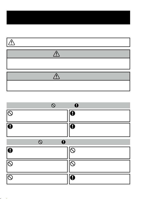
Safe Usage
Thisinstructionmanualcontainsvariouswarningsforyoursafetyandproperusagetoavoid
possible personal injury. Please be sure to heed the warnings and strictly follow safety
instructions.
This symbol signifies that improper usage may result in injuries or
damage.
EnvironmentalWarnings-Warning-Caution
UsageWarnings-Warning-Caution
Caution
Caution
Caution
DONOTUSETHERMOMETERWHENITISWETOR
SOAKEDINLIQUID.
Althoughtheproductiswater-resistant,usingitwithwater
dropsonitslensorinwetconditionsmaycauseincorrect
measurement.
AVOIDMEASURINGSHINYOBJECTS.
Shinyobjectsreectsurroundingtemperatures.Incorrect
measurementmayoccuralthoughspecifyingtheemissivity
ratecancorrectit.
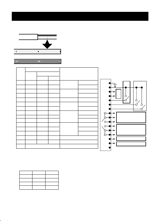
DONOTUSEWITHNON-STANDARDVOLTAGE.
Usingtheunitoutof12to24VDCrangemayresultin
damagetotheunit,shorts,resandinjuries.Insuchcases,
immediatelyswitchtheunitoff.
DONOTTOUCHTHELENS.
Donottouchthelenswithhardorsharpobjects.Donot
insertforeignobjectsintothelightreceivingpart.Otherwise
incorrectmeasurementwilloccur.
KEEPTHETHERMOMETERAWAYFROMDIRECT
SUNLIGHT,DUST,HIGHTEMPERATURESANDHIGH
HUMIDITYDURINGUSEANDSTORAGE.
Otherwiseitmaycauseirreparabledamageorincorrect
measurement.
DONOTDROPTHISTHERMOMETERNORGIVE
ASTRONGIMPACTTOIT,WHICHMAYCAUSE
IRREPARABLEDAMAGEORINCORRECTMEASUREMENT.
Otherwiseitmaycauseirreparabledamageorincorrect
measurement.
DONOTLETTHETHERMOMETERTOUCHTHEOBJECT
THATISBEINGMEASURED.
Thisproductisanon-contactthermometer.Touchinghigh-
temperatureobjectmaycausedeformationofthemeter,
irreparabledamageorincorrectmeasurement.
DONOTBRINGTHETHERMOMETERCLOSETO
ELECTRICALLYCHARGEDOBJECTS.
Otherwiseitmaycauseirreparabledamageorincorrect
measurement.
KEEPTHETHERMOMETERAWAYFROMSUDDEN
CHANGEINAMBIENTTEMPERATURE.
Suddentemperaturechangemaycauseincorrect
measurement.Startmeasurementwhentemperaturehas
becomestableafterleavingthemeterforawhile.
KEEPTHETHERMOMETERAWAYFROMPRODUCTS
WHICHPRODUCESTRONGELECTROMAGNETIC
WAVES.DONOTUSEINANATMOSPHERECONTAINING
CORROSIVEGASESOREXPLOSIVEGASES.
Otherwiseitmaycauseirreparabledamageorincorrect
measurement.

4
Accessories:MountingNut(M12×P1.0)×2
Options:BlackBodyTape HB-250, Mounting FittingCS-FB12, Changeable Laser Marker CS-LDP,
AirPurgeCollarCS-AP1,CFLensCS-CF01,MassiveHousingUnitCS-MH01
*Thespecicationsaresubjecttochangewithoutnoticeforproductimprovement.
*ForChinaRoHS,pleaserefertohttps://www.optex-fa.com/rohs_cn/
Specications
Model
CS-30TAC-HT CS-40TAC-HT
CS-30TAC CS-40TAC
Temperaturerange 0°C to 1000°C -40°C to 500°C
Areasize φ30/500 mm
22:1
φ40/500 mm
15:1
φ30/500 mm
22:1
φ40/500 mm
15:1
Optics Siliconlens(Water-repellentcoat,Oil-repellentcoat)
Detectionelement/
Wavelength Thermopile/8to14μm
Responsespeed 150msec/90%
Accuracy
0 to 200°C:±2°C
201 to 1000°C:Readingvalue±1%
-40 to 0°C:±3°C
1 to 200°C:±2°C
201 to 500°C:Readingvalue±1%
Measurementcondition:ε=1.0,23±5°C,Measurementdistance250mm,Targetsize
φ
100 mm
Repeatability Upto200°C:±1.0°C
201°Candmore:±0.5%
Emissivityrateadjustment
0.1to1.2
Powersupply 12to24VDC±10%
Consumption 120mA(Max.load),80mA(Ecomode)
Ambienttemperature Sensorhead:0to180°C,Amplier:0to65°C Sensorhead:0to100°C,Amplier:0to65°C
Ambienthumidity 35to85%(withoutcondensation)
Storagetemperature 0 to 70°C
Waterresistance Sensorhead:IP69K,Amplier:IP40
Vibrationresistance 10to55Hz,1.5mmamplitude,2hourseachforXYZdirections
Mainmaterial Sensorhead:SUS,Amplier:ABS
Dimensions Sensorhead:Approx. φ14(M12)×34mm,Amplier:Approx.35×52×39mm
Weight
Sensorhead:Approx.100g(includingacableof3m),
Amplier:Approx.200g(includingacableof2m)
Display LED
Resolution 1°C
Analogoutput 4 to 20 mA
Analogoutputresolution 0.5°C
Analogoutputaccuracy ±0.5%or±1.0°C
Analogoutputupdatingtime
10msec
Analogoutputallowableload
250Ω
Analogoutputimpedance 47Ω
Contactoutput PhotoMOSFET×2(ccontact×2),300mA/30VDCorless
Others Triggerinput
Bank×4
Applicableregulations
EMCDirective(2014/30/EU),RoHSDirective(2011/65/EU),ChinaRoHS(MIITOrderNo.32)
Applicablestandards EN61326-1:2013

5
External Dimensions/Part Name
Lenssurface
φ7
M12×P1.0
10
30
φ14
●Sensorhead
Sensorcable
φ4×3000(MAX)
Cablecover
SerialNo.
▲/▼buttons
ENT.button
Outputcable
φ6×2000(MAX)
CableNo.
Maindisplay
●Amplier
Subdisplay
64
52
35 39
31
[mm]
DINrailattachmentpart
CableNo.
φ10
4

6
Wiring Diagram
BANK (1) (2)
1OPEN OPEN
2CLOSE OPEN
3OPEN CLOSE
4CLOSE CLOSE
15pieces(AWG26)
Dotmark1
Dotmark2
No.
Outputcable
Descriptions
Line
color
Dotmark
Color
Quantity
1 Pink Red 1 Powersupply 12to24VDC
2Gray Black 1GND
3 White Red 1
Analogoutput
4-20 mA
+
4 White Black 1-
5 Pink Black 1
Externaltrigger
Input
6Gray Black 2Bankswitch (1)
7 White Red 2 (2)
8Yellow Red 1 Alarmoutput
H
N.C.
9Gray Red 1 COM
10 Yellow Black 1N.O.
11 Orange Red 1 Alarmoutput
L
N.O.
12 Gray Red 2 COM
13 Orange Black 1N.C.
14 Orange Red 2 Donotwire
15 Orange Black 2ConnecttoGND
16 *4(Shieldedcable) -
●Outputcable
*1 Connecttothe4-20mAinputofananalogdevice.
Analogoutputallowableload250Ωandanalogoutputimpedance47Ω
*2 Externaltrigger:Switcheson/offintherangefrom2to5.
*3 Bankswitch:SwitchesOPEN/CLOSEintherangefrom2to6orfrom2to7toselectabank.
*2 *3
c contact
300mA/30VDCorless
c contact
300mA/30VDCorless
Donotwire
ConnecttoGND
*1
*4 Whenyoucut theoutputcablesshorter, a shielded cableforreinforcementwillcomeout.Cutthe
shieldedcabletopreventitfromcontactingwithothercables.
*Cables not used should be cut so that they do not contact with other cables, and insulated with
adhesivetapeorbyothermethods.

7
Sensor
cable
Connector
No.
Green 1
Yellow 2
Brown 3
Shield 4
-5
Whenyoucutthesensorcables,ensuretoperform
endtreatmentandconnectionofthecables.Inthe
caseoftheshortcircuitofthesensorcables,the
sensorcannotmeasureprecisely.
(1)Cutthecablestoadesiredlengthandtreattheir
endasshownintheleftgure.
Aguidewireissheathedintheshieldedmesh
cable.Cuttheothercablesthantheguidewireat
theirbase.
(2)Passthesensorcablebundlethroughthehole
ofthecablecoverandtightenthecabletieatthe
pointshownintheleftgure.
*Theserialnumbersareprintedonthecablecover.
Makesuretoputeachsensorcablesbacktothe
sameholesthatyouremoved.
(3)Connectthecablesandshieldedcable(guide
wire)totheconnector.
(4)Inserttheconnectortothecablecover.
*Themetalplateofconnectorshouldbeplacedonto
theclaspinthecablecover.
●Sensorcable
5
15
5
Cabletie
(ofapprox.2
mmwidth)
Guidewire
(1)
(2)
(3)
(4)
[mm]
○ Connectingthesensorcables
Keepingtheconnectorpushed
in,tthecablecovertothe
groovesoftheamplier,and
insertthecablecover.
○ Removingthesensorcables
Pinchthetabofthecable
coverandpullthecable
coverupward.
Sensorheadandamplierhas
beencalibratedasaset.
Makesuretousesensorhead
andamplierwiththesame
serialnumber.
Amplierhasnotaprotectivestructure. Whenyouconnecttheoutputcableandthesensorcable,
makesurethatthewateroroildoesnotpenetratetoamplieralongthecable.Whenusedinsuch
anenvironmentwherewateroroilmightgetintotheamplier,pleaseuseoptionalprotectivecase.
(EquivalenttoIP65)
Pleasenotedthatcontinuoushotwaterwithhighpressuremaycausebreakageofthecableorcovering.

8
Mounting/Installation
●Sensorhead
●Amplier
MounttheamplierontheDINrailusingthehooksonitsbottom.
Avoidalocationwherewateroroilmayspillonit. ○ Mounting
MakethetwohooksontheSWsidecatch
theDINrailandpushintosettheamplier.
(1)
(2)
(1)
(2)
○ Removing
PushthetwohooksontheSWsidetothe
oppositedirectionandraisetheamplier.
TheexternalscrewisM12×P1.0.
Fixsecurelyintotheholeofφ12mmormoreusingtheattachedhexagonnut.
Theoptionalmountingttingcanhelpyouadjusttheangleeasily.
○Mounting
Mountthesensorheadperpendiculartothe
target.
Avoidalocationwherethesensorheadmay
beexposedtovibrationorimpact.
Theambienttemperatureshouldnotrapidly
changeandshouldbewithintheoperating
temperaturerange.
Donotxthecablewhenitisbentor
excessiveloadisappliedtoit.
Althoughthesensorheadiswater-resistant,
waterdropsonthelensmaycauseanerror.
90°
Target

9
Field of View
[CS-30TAC/CS-30TAC-HT]
[CS-40TAC/CS-40TAC-HT]
φ12/100
φ21/300
φ30/500
φ14/100
φ27/300
φ40/500
[CS-30TAC/CS-30TAC-HT + CF] [CS-40TAC/CS-40TAC-HT + CF]
φ0.6/12 φ1.0/12
φ25/50
φ26.5/50
[Forcorrectmeasurement]
Therangeofeldofviewisequivalentto90%ofopticalresponse(energy).
Thetargetshouldbesufcientlylargerthantheeldofviewshownabove.
Whenmeasuringahigh-temperaturetarget,keepasmuchdistancefromitaspossiblewithintherange
oftheeldofview.Otherwiseitmaycauseincorrectmeasurement.
●WhenusingtheoptionalCFlens
* WhentheCFlensisattached,correctionisnecessarybecauselightintensityreceivedfromthetarget
decreasesby20to30%.
Whenmeasuringaminutespot,therecommendedtargetsizeisapproximately1.5timesoftheeld
ofviewshownabove.
[mm]
[mm]
Areasize/Distance
Areasize/Distance
D(distance):S(area)=22:1
D:S=15:1
φ7/0
φ7/0

10
How to Use
(1) Conrmthewiringsandthenturnthepoweron.
Thedisplayashesandthentemperaturemeasurement
starts(NormalOperation).
(2) Conrmthatthemeasurementvaluechangeswhenyouput
yourhandintotheeldofview.
*LeavetheUnitforawhileafterthesensorheadismounted.
Temperaturechangemaycauseincorrectmeasurement.
25
E1.00
MODE
8888
NormalOperation
Press3sec.ormore
SettingOperation
*MakesuretoperformSaveSettings.
IfyoucancelinSaveSettings,allsettingsenteredarenotsaved.
8.8.8.8
8.8.8.8
(3) ToconrmorchangethesettingspresstheENTERbutton
forthreesecondsormore.
ThedisplayashesandthenSettingOperationstarts.
(4) Selectthefunctionwith▲/▼buttons.
ENT.
END
SET
SaveSettings
BANK
1
➊Bank Setting
DELY
1
➋Response
Time Setting
TADJ
E1.00
➌ Adjustment
Setting
ASCL
-40
➍ AnalogOutput
Setting
ALAM
400
➎ AlarmOutput
Setting
TRIG
NoN
➏ TriggerInput
Setting
ECO
OFF
➐DisplayOff
Setting
▲button:
▼button:

11
Function List
Tochangethesettings,presstheENTERbuttonforthreesecondsormore.
Thesettableitemsareshownbelow.
Changethesettingsasnecessary.
Whiletheindicationashes,thesettingsarebeingreadorwrittenandthebuttonoperation
isnotavailable.
No. Function Descriptions
➊Bank
Setting
Selectthebank(1to4)tochangethesetting.
SettingsofResponseTime,Adjustment,AnalogOutput,AlarmOutput,TriggerInput,and
DisplayOffcanbesavedineachbank.Selectthebankbycableconnections.
➋Response
Time
Setting
Selecttheresponsetime.
Youcanselect1to200ofthemovingaveragetimes.
Thelargernumber,thelongerresponsetimeandthesmootheructuation.
➌Adjustment
Setting
Adjustthemeasurementvalue.
TheUnithas3methodsfortheadjustmentasbelow;
TEACHAdjustment :
Adjustthemeasurementvaluetothetemperaturevalueofthetarget.
EmissivityRateAdjustment
:Inputtheemissivityratedirectly.
2PointAdjustment :Adjustthemeasurementvalues(2points)tothetempera-
turevalues(2points)ofthetarget.
➍Analog
Output
Setting
Adjusttheanalogoutput(4-20mA)range.
Youcansetuphigherlimitvalue(valuefor20mA)andlowerlimitvalue(valuefor4mA).
➎Alarm
Output
Setting
Makethealarmoutputsettings.
AlarmOutputMode,temperatureofalarmoutputandalarmON/OFFcanbeset.
TheUnithas3AlarmOutputModesasbelow;
NORMALMode :
Alarmoutputiskeptonaslongasthevalueisaboveorbelowthelimitvalue.
DELAYMode :Alarmoutputturnsonwhenaspecictimeperiodpassesafter
thevalueexceedsorfallsbelowthelimitvalue.
ONE-SHOTMode :Alarmoutputturnsonwhenthevalueexceedsorfallsbelowthe
limitvalueandiskeptforaspecictime.
➏Trigger
Input
Setting
Makethetriggerinputsettings.
Triggerinputmode,analogoutputtype,andtriggerON/OFFcanbeset.
TheUnithas2TriggerModesasbelow;
ExternalMode :AnalogOutputiscontrolledbyExternalTrigger.
WAVEMode :
AnalogOutputiscontrolledbythejudgmentcriterionvalue(WAVELIMIT).
TheUnithas4analogoutputtypesasbelow;
MAXHOLD :Themaximumvaluebetweenthetriggersisoutput.
MINHOLD
:Theminimumvaluebetweenthetriggersisoutput.
P-PHOLD
:Thedifferencebetweenthemaximumandminimumvaluesbetweenthe
triggersisoutput.(ForExternalModeonly)
SAMPLEHOLD
:Thevalueatthemomentofthetriggerisoutput.(ForExternalModeonly)
➐DisplayOff
Setting
Makethedisplayoffsettings.
YoucanreduceconsumptioncurrentbyturningoffthedisplayduringNormalOperation.
Iftheunitisleftunoperatedfor60secondsormore,itreturnstoNormalOperation.Inthis
case,thesettingsarecancelled.MakesuretoperformSaveSettings.
MODE
8888
END
SET
END
SET
BANK
1
Flashing/Buttonoperationisnotavailable Lighting/Buttonoperationisavailable

12
TADJ
E1.00
Setup of Functions
Adjustthetemperaturemeasurementvalue.
TheUnithas3methodsfortheadjustmentasbelow;
TEACHAdjustment :Adjustthemeasurementvaluetothe
temperaturevalueofthetarget.
Themeasurementvalueisoutputbasedon
theemissivityratecalculatedautomaticallyin
TEACHAdjustment.
EmissivityRateAdjustment :Inputtheemissivityratedirectly.
2PointAdjustment :Adjustthemeasurementvalues(2points)
tothetemperaturevalues(2points)ofthe
target.
Cancel :CanceltheAdjustmentSetting.Theunit
returnstotheSettingOperation.
TECH
E1.00
E
E1.00
AADJ
OFF
TEACH
Adjustment Emissivity
Rate
Adjustment
2 Point
Adjustment
NON
SET
Cancel
➌AdjustmentSetting
Selectthebank(1to4)tochangethesetting.
SettingsofResponseTime,Adjustment,AnalogOutput,AlarmOutput,
TriggerInput,andDisplayOffcanbesavedineachbank.
(1)IntheSettingOperationselecttheBankSetting,andthenpress
Enterbutton.
(2)Selectthebanknumber,andthenpressEnterbutton.
*MakesuretoperformSaveSettingsandselectthebankbycable
connection.
DELY
1
BANK
1
BANK
4
DELY
200
Selecttheresponsetime.
Youcanselect1to200ofthemovingaveragetimes.
Thelargernumber,thelongerresponsetimeandthesmoother
uctuation.
1=approximately0.15sec.to200=approximately10sec.
(1)IntheSettingOperationselecttheResponseTimeSetting,and
thenpressEnterbutton.
(2)Selectthemovingaveragetimes,andthenpressEnterbutton.
MakesuretoperformSaveSettings.
➊Bank Setting
➋ResponseTimeSetting
*SettingCancelwithSETreturnstheunit
tothestateofbeforemakingthesetting.

13
TECH
E1.00
150
150
150
160
160
E0.90
E
E1.00
E
E0.95
Emissivityrate(ε)
Theemissivityrateistherateofenergyemittedfromthesurfaceofanobject.Everyobjecthas
auniqueemissivityratewhichisvariableaccordingtothesurfaceconditionandtemperatureof
theobject.Thisproductallowsforsettingadesiredemissivityrate,whichcanenableevenmore
precisemeasurementbyadjustingtheemissivityrateaccordingtothatofthetarget.
Anobjectwithlowemissivityrate(e.g.ashinymetallicobject)reectsthesurrounding
temperaturesinceitishighlyreective.Ifthesurroundingobjectshavegreatlydifferent
temperaturefromthatofthemainunit,theirtemperaturesarereectedresultinginincorrect
measurement.Thereforeitisnecessarytoblockoutsucheffect.
Themaximumemissivityrateisnormally1.00,butthisunitisdesignedtoacceptupto1.20for
practicalconvenience.
(1)Aimthesensorheadtothetarget.
Conrmthetargetissufcientlylargerthantheeldofview.
(2)
IntheSettingOperationselecttheAdjustmentSetting,andthenpressEnterbutton.
(3)SelecttheTEACHAdjustment,andthenpresstheENTERbutton.
(4)Thecurrentmeasurementvalueisdisplayed.
Inputthetemperatureofthetarget,andthenpresstheENTERbutton.
(5)Conrmthatthemeasurementvalueandemissivityratehavebeenchanged.
MakesuretoperformSaveSettings.
(1)IntheSettingOperationselecttheAdjustmentSetting,
andthenpressEnterbutton.
(2)SelecttheEmissivityRateAdjustment,andthenpress
theENTERbutton.
(3)
Inputtheemissivityrate,andthenpresstheENTERbutton.
(4)Conrmthatthemeasurementvalueandemissivityrate
havebeenchanged.
MakesuretoperformSaveSettings.
○TEACHAdjustment
○EmissivityRateAdjustment
Err1
E
Error indication
IftheemissivityratecalculatedautomaticallyintheTEACHAdjustmentisoutofthesetting
range(0.1to1.2),anerror(Err1)isdisplayed.
Inthiscase,TECHAdjustmentiscancelled.PerformEmissivityRateAdjustment.
Inputtheemissivityratedirectly.
Adjustthemeasurementvaluetothetemperaturevalueofthetarget.
Theemissivityratioiscalculatedautomatically.

14
Setup of Functions
AADJ
OFF
AADJ
ON
L
EXIt
100
120
120
SET
H
EXIt
L
SET
H
SET
250
300
300
SET
○2PointAdjustment
(1)Aimthesensorheadtothetarget.Conrmthetargetissufciently
largerthantheeldofview.
(2)IntheSettingOperationselecttheAdjustmentSetting,andthen
pressEnterbutton.
(3)Selectthe2PointAdjustment,andthenpresstheENTERbutton.
(4)SelectON,andthenpresstheENTERbutton.
(5)SelectSET,andthenpresstheENTERbutton.
*TosetthetemperatureH(highervalue)rst,selectEXIT.
(6)Thecurrentmeasurementvalueisdisplayed.
InputthetemperatureL(lowervalue)ofthetarget,andthenpress
theENTERbutton.
Thissettingisforadjustingthemeasurementvaluewiththespeciedvalue
accordingtothemeasuringtargets.Aintendedvaluecanbeoutputbysetting
L(lowervalue)andH(highervalue)conformingtothebothspeciedvalue.
*Measurementaccuracycannotbeguaranteedforthevaluemadeby2
PointAdjustment.
*Donotchangetheemissivityrateaftersettingin2PointAdjustment,
otherwisetheadjustedvaluewillbechanged.
(7)Aimthesensorheadtothetarget.Conrmthetargetissufciently
largerthantheeldofview.
(8)SelectSET,andthenpresstheENTERbutton.
*ToinputthetemperatureH(highervalue)later,selectEXIT.
(9)Thecurrentmeasurementvalueisdisplayed.
InputthetemperatureH(highervalue)ofthetarget,andthen
presstheENTERbutton.
MakesuretoperformSaveSettings.
*IfthetimingstosettemperatureLandHaredifferent(e.g.,whenusingthesametargetfor
settingLandH),seteitherofthemrstandperformSaveSettings.Otherwisethe2Point
Adjustmentwillbecancelled.
*TheadjustedvalueareeffectiveafterthebothoftemperatureLandHaresaved.
While2PointAdjustmentison,2PointAdjustmentindicatoris
displayedonsubdisplay.
IfthesettingoftemperatureLorHvalueisnotsaved,the
measurementvalueisoutputbasedonthesettingstoredpreviously.
But2PointAdjustmentindicatorisdisplayedonthesubdisplay.
EXIT
300
AADJ
Adjustthemeasurementvalues(2points)tothetemperaturevalues(2points)ofthetarget.

15
ASCL
-40
H(higherlimitvalue):Valuefor20mA
L(lowerlimitvalue) :Valuefor4mA
*ThecurrentSettingvalueisdisplayedrstonsub
display.
➍AnalogOutputSetting
ASCL
500
(1)IntheSettingOperationselecttheAnalogOutput
Setting,andthenpressEnterbutton.
(2)H(higherlimitvalue)isdisplayed.Inputthe
temperatureH(higherlimitvalue),andthenpress
Enterbutton.
H
500
H
300
L
-40
L
0
(3)L(Lowerlimitvalue)isdisplayed.Inputthe
temperatureL(lowerlimitvalue),andthenpress
Enterbutton.
MakesuretoperformSaveSettings.
*Theminimumwidthofoutputrangeis100degrees.
0to1000°C:4–20mA ->100to200°C:4–20mA○
->100to180°C:4–20mA×
Temperature
Energy Energy
Temperature Afteradjustment
Temperature
Output Output
Temperature
Theminimumtemperaturewidthforhighervalueandlowervalueis10
degrees.
300
250250
100100
120
300°C
500°C
-40°C
4 mA 4 mA20 mA 20 mA
0°C
Youcansetuphigherlimitvalue(valuefor20mA)andlowerlimitvalue(valuefor4mA).

16
Setup of Functions
➎ AlarmOutputSetting
ALAM
400
H(higherlimitvalue) : Alarmoutputturnsonwhenthe
measurementvalueexceedsthe
Settingvalue.
L(lowerlimitvalue) : Alarmoutputturnsonwhenthe
measurementvaluefallsbelowthe
Settingvalue.
TheUnithas3AlarmOutputModesasbelow;
ALAM
50
OUT
NOR
OUT
DEL
OUT
ONES
ONE-SHOTMode
Alarmoutputturnsonwhenthevalueexceeds
orfallsbelowthelimitvalueandiskeptfora
specictime.
NORMALMode
Alarmoutputiskeptonaslongasthevalueis
aboveorbelowthelimitvalue.
DELAYMode
Alarmoutputturnsonwhenaspecictime
periodpassesafterthevalueexceedsorfalls
belowthelimitvalue.
Measurementvalue
Alarmoutput
H
L
ON
OFF
t:Timetodelayoutput
Measurementvalue
Alarmoutput
H
L
ON
OFF t
Measurementvalue
t:Timetokeepoutputon
Alarmoutput
H
L
ON
OFF t
Alarmoutputmode,temperatureofalarmoutputandalarmON/OFFcanbeset.

17
○Outputmode
H
OFF
L
OFF
OUT
NOR
(1)IntheSettingOperationselecttheAlarmOutputSetting,andthenpress
Enterbutton.
(2)SelectON,andthenpresstheENTERbutton.
*Tocancelthesetting,selectOFFandpresstheENTERbutton.
(3)TheH(higherlimitvalue)isdisplayed.
InputthetemperatureH(higherlimitvalue),andthenpresstheENTERbutton.
(4)SelectON,andthenpresstheENTERbutton.
*Tocancelthesetting,selectOFFandpresstheENTERbutton.
(5)TheL(lowerlimitvalue)isdisplayed.InputthetemperatureL(higherlimit
value),andthenpresstheENTERbutton.
(6)SelectNORMALMode,andthenpresstheENTERbutton.
MakesuretoperformSaveSettings.
(6)SelectDELAYMode,andthenpresstheENTERbutton.
(7)TheDELAYTimeisdisplayed.
InputtheDELAYTime,andthenpresstheENTERbutton.
TheDELAYTimerangeis0.01to2.00seconds.
MakesuretoperformSaveSettings.
TosetupDELAYMode
TosetupONE-SHOTMode
TosetupNORMALMode
(6)SelectONE-SHOTMode,andthenpresstheENTERbutton.
(7)ONE-SHOTTimeisdisplayed.
InputtheONE-SHOTTime,andthenpresstheENTERbutton.
TheONE-SHOTTimerangeis0.01to2.00seconds.
MakesuretoperformSaveSettings.
H
ON
H
400
H
300
L
ON
L
50
L
0
OUT
DEL
TIME
0.010
TIME
2.000
OUT
ONES
TIME
0.010
TIME
2.000

18
TRIG
NoN
Triggerinputmode,analogoutputtype,andtriggerON/OFFcanbeset.
ExternalMode:AnalogOutputiscontrolledbyExternalTrigger.
WAVEMode :AnalogOutputiscontrolledbythejudgmentcriterionvalue
(WAVELIMIT).
TRIG
NoN
Nosetting
TRIG
EXT
ExternalMode
TRIG
WAVE
WAVEMode
➏TriggerInputSetting
MAXHOLD:
Themaximumvalue
betweenthetriggersis
output.
TheUnithas4analogoutputtypesasbelow;
HOLD
MIN
MIN
HOLD
P-P
P-P
HOLD
SAMP
SAMPLE
Setup of Functions
MINHOLD:
Theminimumvalue
betweenthetriggersis
output.
HOLD
MAX
MAX
P-PHOLD:
TheP-Pvalue(maximum
minusminimum)between
thetriggersisoutput.(For
ExternalModeonly)
SAMPLEHOLD:
Thevalueatthemoment
ofthetriggerisoutput.
(ForExternalModeonly)
Triggerinput
Analogoutput
Measurement
value
ON
MAX
MIN
OFF
Triggerinput
Analogoutput
Measurement
value
ON
MAX
MIN
OFF
Triggerinput
Analogoutput
Measurement
value
ON
MAX
MIN
OFF
Triggerinput
Analogoutput
Measurement
value
ON
MAX
MIN
OFF

19
TRIG
EXT
(1)IntheSettingOperationselecttheTriggerInputSetting,andthenpressEnter
button.
(2)SelecttheExternalMode,andthenpressEnterbutton.
(3)Selecttheanalogoutputtype,andthenpressEnterbutton.
MakesuretoperformSaveSettings.
○ExternalMode
HOLD
MAX
HOLD
MIN
HOLD
P-P
HOLD
SAMP
TRIG
WAVE
(1)IntheSettingOperationselecttheTriggerInputSetting,andthenpressEnter
button.
(2)SelecttheWAVEMode,andthenpressEnterbutton.
(3)Selecttheanalogoutputtype,andthenpressEnterbutton.
*IntheWAVEMode,MAXHOLDorMINHOLDisavailablefortheanalogoutput
type.
(4)Inputthejudgmentcriterionvalue(WAVELIMIT),andthenpressEnterbutton.
MakesuretoperformSaveSettings.
○WAVEMode
HOLD
MAX
HOLD
MIN
WIMT
200
WLIM
150
WIMT
200
WLIM
150
AnalogOutputiscontrolledbyExternalTrigger.
AnalogOutputiscontrolledbythejudgmentcriterionvalue(WAVELIMIT).
*IntheMAXHOLD,P-PHOLDandSAMPLEHOLDanalogoutputremaintheminimumvalue(4mA)
untilthersttrigger.
IntheMINHOLDanalogoutputremainthemaximumvalue(20mA)untilthersttrigger.
Samplingstartsatthersttrigger,andtheanalogoutputcontrolstartsatthesecondtrigger.
WAVEMAXHOLD WAVEMINHOLD
*IftheAlarmOutputSettinghasbeenset,thejudgmentcriterionwillbetheanalogoutputcontrolledby
theTriggerInputSetting.->Page20
Triggerinput Triggerinput
Analogoutput
Analogoutput
Measurementvalue Measurementvalue
ON ON
MAX MAX
MIN MIN
WAVE
LIMIT
WAVE
LIMIT
OFF OFF

20
●Combinationofalarmoutputandtriggerinput
Setup of Functions
Thisunitallowsindividualsettingforeachfunction.
Thebehaviorwhenthealarmoutputandtriggerinputarecombinedisasdescribedbelow.
Thealarmoutputusestheanalogoutputvalueasthejudgmentcriterion,sowhenthetrigger
inputisset,thecontrolledanalogoutputwillbethejudgmentcriterion.
Settingvalue
Alarm: H/Lsetting NORoutput
Trigger:Externaltrigger MAXHOLD
AccordingtotheanalogoutputofMAX
HOLDsetbythetriggerinput,alarm
isoutputwhilethevalueisoutsidethe
rangebetweenHandL.
Settingvalue
Alarm: (1)H/Lsetting NORoutput
(2)H/Lsetting DELoutput
(3)H/Lsetting ONESoutput
Trigger:WAVEtrigger MAXHOLD
AccordingtotheanalogoutputofMAX
HOLDsetbythetriggerinput,alarm
isoutputwhilethevalueisoutsidethe
rangebetweenHandL.
ECO
OFF
(1)
IntheSettingOperationselecttheDisplayOffSetting,andthenpressEnterbutton.
(2)SelectON,andthenpresstheENTERbutton.
*Tocancelthesetting,selectOFFandpresstheENTERbutton.
(3)InputtheDisplayOFFTime,andthenpressEnterbutton.
TheDisplayOFFTimerangeis1to600seconds.
MakesuretoperformSaveSettings.
ECO
ON
➐DisplayOffSetting
ECOT
1
ECOT
600
.
WhenECOisON
Asingledotislighting.
Triggerinput Triggerinput
Alarmoutput Alarmoutput
(1)NOR
Alarmoutput
(2)DEL
Alarmoutput
(3)ONES
Analogoutput
Analogoutput
Measurementvalue
Measurement
value
ON
MAX
H
L
MIN
HON
LON
OFF
MAXHOLD
OFF
ON
MAX
MIN
H
L
HON
HON
HON
LON
LON
LON
OFF
OFF
OFF
OFF
WAVE
LIMIT
t
t
tt
YoucanreduceconsumptioncurrentbyturningoffthedisplayduringNormalOperation.
This manual suits for next models
3
Table of contents
Other OPTEX FA Thermometer manuals