WITH PoE
The OSD2052P is designed to convert between
10/100Base-T copper cabling and 100Base-Fx fiber via
the SFP port and includes PoE source on one RJ45.
Operation over at least 40km of singlemode fiber is
possible by use of the appropriate optical devices. The
unit operates over one or two fibers depending on the
SFP used. It is equipped with one SFP port, two RJ45
connectors (PoE available on one RJ45) and power
jack. For ease of network monitoring and fault isolation
the OSD2052P has 6 indicators (see tables).
Specifications and Features
▲
Two 10/100Base-T RJ45 ports and one SFP fiber
port
▲
Supports IEEE802.af Alternative A and B cable
wiring on one RJ45 port
▲
Complies with the IEEE 802.3af standard
including compliant powered device (PD)
signature detection and classification.
▲
Provides up to 15.4W to the PD.
▲
Supports network traffic of 10 or 100Mbps.
▲
Automatic TP setup: no need for crossover cables
▲
Auto-sensing of half or full duplex operation.
▲
Automatic set up for 10 or 100Mbps on copper
side.
▲
A very compact design that fits in the camera
housing
▲
Available for singlemode, multimode operation
over a variety of link budgets
▲
Available for operation over 1 or 2 fibers
▲
Powered by non-critical 10 to 35VDC or 24VAC
supplies
▲
Operates over –20 to +75°C temperature range
▲
Utilizes 10/100Base-Fx SFP transceivers that can
be selected according to specific length or fiber
requirements without changing the whole unit
Power Over Ethernet (PoE) Feature
The OSD 2052P Rugged Power over Ethernet (PoE) bridge
media converter is a Power Sourcing Equipment (PSE) which
provides fully isolated means of powering devices via UTP
cables. It enables economical implementation of backup
power. Power to remote location can be delivered with a
simple inexpensive installation of UTP cable. Customer's
powered devices (PD) can use either Alternative A or
Alternative B, i.e. either sets of wire pairs (1/2, 3/6 or 4/5, 7/8).
The OSD2052P is equipped with safety features for protection
of UTP cables and network equipment. Output is protected for
short-circuit, undervoltage, and overvoltage. Inrush current is
limited and there is a thermal shutdown. The OSD2052P will
not apply power unless it detects PD signature. Powered
device (PD) controller must comply with 802.3af standard.
OSD2052P turns on PoE indicator when it detects a valid PD.
Fitting SFP Connectors
Care should be taken when inserting/removing the SFP
connectors as SFP modules are Electrostatic (ES) sensitive
and Electrostatic Discharge (ESD) precautions should be
taken when installing. Ensure that the SFP is fully engaged
and latched into position.
Inserting SFP – Ensure that the SFP lever is in the locked
position and insert into SFP port. Gently push the SFP until it
locks into place. Remove dust cap and fit fiber cable.
Removing SFP – Remove fiber connector. Pull the SFP lever
down to unlock SFP from housing. Using the lever, gently pull
the SFP out.
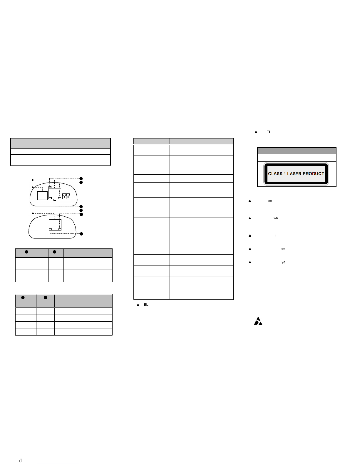
Case Dimensions and Mounting Details
Below is an outer case drawing showing the dimensions.
The OSD2052P can be mounted on the optional mounting
base clips by simply utilizing the OSD2052P ribbed edge.
Dimensions below
Power Connection
The voltage range of the OSD2052P is 10V
DC
to 35V
DC
or
22 to 28V
AC
@ 2VA. Connect power to the connector
located at the front of the case (see diagram).
Signal Connection
Cat5 or higher Ethernet cable should be connected to the
RJ45 Copper connectors on the OSD2052P. The
appropriate SFP connector should be inserted into the
SFP port.
The optical fiber cable must be terminated with the
appropriate type optical connector (SC for single fiber and
LC for 2 fiber). Before connection, inspect the ends of the
connectors to ensure that no dust or dirt is present as it
could contaminate the modem connector and result in
poor performance.
If it is necessary to clean the cable connectors use
isopropyl alcohol and lint free tissue to remove
contamination.