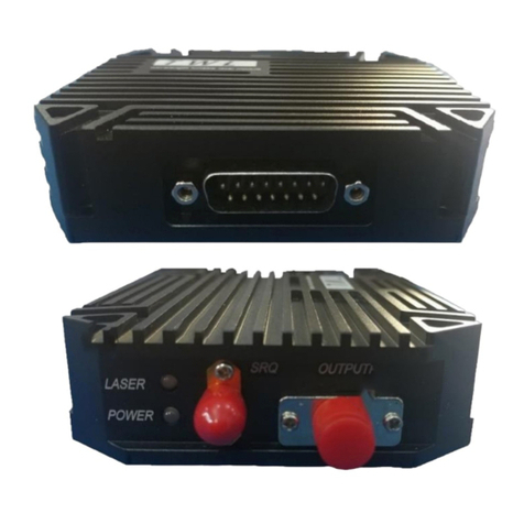
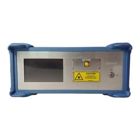
OPTILAB Phoenix Series User manual

Optilab TWL-P-HS User’s Manual
High Speed Tunable Wavelength Laser –Phoenix Series
Caution: The user must read this manual before operating the SOA-M unit. Operations
other than those described in this manual may result in personal injury and
damage to the unit.
Note that any attempt to open or fix the equipment without prior approval by
Optilab, LLC. voids the warranty.
Ver. 1.2
August 12th, 2021

TWL-P-HS User’s Manual
Page ii of iii
Optilab, LLC
600 E. Camelback Road, Phoenix, AZ 85012
Phone: (602) 343-1496, Fax: (602) 343-1489, Email: sales@oequest.com
Revision History
VERSION
DATE
SUMMARY
1.0
06/01/2019
Manual introduced
1.1
03/05/2020
Updated front page, Main menu photo, ITU Grid
1.2
08/12/2021
Format update
Copyright ©2021 by Optilab, LLC
All rights reserved.
This document is copyrighted property of Optilab, LLC. It may not be used in whole or in part for
manufacture, sale, or design of items without the written permission of Optilab, LLC.
Information herein is preliminary and subject to change without any notices.

TWL-P-HS User’s Manual
Page iii of iii
Optilab, LLC
600 E. Camelback Road, Phoenix, AZ 85012
Phone: (602) 343-1496, Fax: (602) 343-1489, Email: sales@oequest.com
Table of Contents
1. GENERAL INFORMATION 1
1.1 INTRODUCTION 1
1.2 PRODUCT OVERVIEW 1
1.3 USER SAFETY 1
2. OPERATION 2
2.1 INTRODUCTION 2
2.2 INITIAL INSPECTION 2
2.3 CONTROLS 3
2.4 OPERATION INSTRUCTIONS 4
2.4.1 START-UP PROCEDURE 4
2.4.2 CONTINUOUS WAVE (CW) MODE 4
2.4.3 SWEEP MODE 5
2.4.4 SHUTDOWN PROCEDURE 7
2.4.5 PATCHCORD SWAPPING PROCEDURE 7
2.5 PC CONNECTION MODE (OPTIONAL) 7
TABLE 1. ITU GRID CHANNEL SPACING 8
3. TROUBLESHOOTING 9
4. SERVICE AND SUPPORT 10
4.1 WARRANTY 10
4.2 SERVICE AND CALIBRATION 10
4.3 CARE OF FIBER-OPTIC CONNECTORS 11

TWL-P-HS User’s Manual
Page 1 of 11
Optilab, LLC
600 E. Camelback Road, Phoenix, AZ 85012
Phone: (602) 343-1496, Fax: (602) 343-1489, Email: sales@oequest.com
1. General Information
1.1. Introduction
This manual contains information on the installation and operation of the TWL-
P-HS High Speed Tunable Wavelength Laser demonstration purposes.
1.2. Product Overview
The TWL-P-HS is a high speed, innovative, all-in-one tunable and
programmable laser source with high spectral purity. Based on laser crystal
technology, the TWL-P-HS can operate in three distinct modes: CW mode,
continuous scan mode, and programmable scan mode over the entire C-band
range. It also features variable scan speed up to 4000 nm/s. Its lightweight and
compact design allow it to be easily utilized both in laboratory and field
engineering applications. A built-in 7” touchscreen with intuitive graphical
interface gives the user full control over the operation of the device. In addition,
the TWL-P-HS can be controlled via remote software through USB or Wi-Fi. Its
polarization output and high wavelength and power stability make it a perfect
solution for a seed laser for optical modulation and other test and measurement
applications.
1.3. User Safety
1. The TWL-P-HS unit emits high intensity invisible light from the optical output
receptacle. Avoid direct exposure to skin and eyes.
2. The user should never open the equipment case; any attempt will void the
warranty and may result in electric shock and EMS attack to equipment in the
vicinity. If requesting to open up the unit for demonstration purposes, please
contact Optilab prior to doing so.
3. The user should avoid using any solvent or vaporizing chemical to clean the
equipment panel or case. It may result in damage to the surface and internal
circuits.

TWL-P-HS User’s Manual
Page 2 of 11
Optilab, LLC
600 E. Camelback Road, Phoenix, AZ 85012
Phone: (602) 343-1496, Fax: (602) 343-1489, Email: sales@oequest.com
2. Operation
2.1. Introduction
This chapter describes how to operate the TWL-P-HS, and discusses the
location and function of the controls and connectors.
2.2. Initial Inspection
Your TWL-P-HS was carefully inspected before it left the manufacturer. It should
be in proper working order upon receipt. You should, however, inspect the unit
for any damage that may have occurred in transit. If the shipping container or
the packing material is damaged, keep it until the contents of the shipment have
been checked to be free of mechanical and electrical damages. Notify Optilab,
LLC promptly if any notable damage is found.
The TWL-P-HS shipment should include the following:
- TWL-P-HS device
- Power Supply

TWL-P-HS User’s Manual
Page 3 of 11
Optilab, LLC
600 E. Camelback Road, Phoenix, AZ 85012
Phone: (602) 343-1496, Fax: (602) 343-1489, Email: sales@oequest.com
2.3. Controls
FEATURE
FUNCTION
POWER SWITCH
This switch toggles the main DC power to the TWL-P-HS
unit.
OPTICAL OUTPUT
PORT
This port provides the optical output from the high speed
tunable wavelength laser.
TRIGGER IN PORT
Reserved.
TRIGGER OUT PORT
This port provides the option to monitor the sweeping period
when the Sweep Mode is enabled.
USB PORT
This USB port is used to communicate with the TWL-P-HS
unit and is not necessary for normal operation. Please
contact Optilab if you wish to know more about this
communication port.
+/-5VDC
CONNECTION PORT
This +/- 5VDC connection port is used to connect to the +/-
5VDC power supply to power up the TWL-P-HS unit.
Top Panel & Side Panel
1
2
3
4
5
6

TWL-P-HS User’s Manual
Page 4 of 11
Optilab, LLC
600 E. Camelback Road, Phoenix, AZ 85012
Phone: (602) 343-1496, Fax: (602) 343-1489, Email: sales@oequest.com
FEATURE
FUNCTION
CW MODE
CW Mode control page.
SWEEP MODE
Sweep Mode control page.
2.4. Operation Instructions
1.1.1 Start-up Procedure
1. Ensure the back surface of the TWL-P-HS has proper ventilation or heat-
sinking.
2. Connect the TWL-P-HS Output (2) to your system or test setup via a
patchcord or optical fiber before powering on the unit. The Output (2)
connector is FC/APC.
3. Depress and hold the power switch on the top left corner of the device until
the LCD screen powers on.
4. The Main page should now be displayed. The user can select between two
modes of operation: Continuous Wave (CW) mode or Sweep mode.
1.1.2 Continuous Wave (CW) Mode
1. To enable continuous wave mode, select the CW mode icon on the Main
page.
2. The continuous wave mode page is displayed as shown below.
3. Set the LD current (1) and Channel Number (2) to achieve desired power
and ITU grid wavelength.
Main Page
1
2

TWL-P-HS User’s Manual
Page 5 of 11
Optilab, LLC
600 E. Camelback Road, Phoenix, AZ 85012
Phone: (602) 343-1496, Fax: (602) 343-1489, Email: sales@oequest.com
4. The wavelength can be further adjusted using Fine Tuning (3).
FEATURE
FUNCTION
LD CURRENT
Sets the desired LD current from 0 to 250 mA. This will
control optical output power.
CHANNEL NUMBER
Sets the desired ITU channel number from 0 to 99. This
will set the output wavelength to the corresponding ITU
grid channel. Refer to table 1 at the end of this section.
FINE TUNING
Fine tunes the output wavelength.
BACK BUTTON
This button will lead you back to the Main page.
OPTICAL POWER DISPLAY
Output optical power display in dBm.
WAVELENGTH DISPLAY
Output wavelength display in nm.
1.1.3 Sweep Mode
1. To enable sweep mode, select the sweep mode icon in the Main page.
2. The sweep mode page is displayed as shown below.
3. Set the Start Channel (1) and Stop Channel (2) to set the desired sweep
range. The actual start and stop wavelength are displayed along with the
channel number.
4. Set the Sweep Time (3). This will determine the period of time it takes to
sweep from start channel to stop channel.
5. Set the LD Current (4). This will determine the optical output power.
CW Mode Control Page
2
3
5
6
4
1

TWL-P-HS User’s Manual
Page 6 of 11
Optilab, LLC
600 E. Camelback Road, Phoenix, AZ 85012
Phone: (602) 343-1496, Fax: (602) 343-1489, Email: sales@oequest.com
6. Select the desired channel spacing (5). 100 GHz spacing will result in
emission of every other channel (e.g. CH19, CH21, CH23, etc). 50 GHz
spacing will result in emission of every channel (e.g. CH19, CH20, CH21,
etc).
7. Push Start (6) to begin the sweep.
FEATURE
FUNCTION
START CHANNEL
Sets the desired channel number from 0 to 99 to set the
START wavelength for sweeping.
STOP CHANNEL
Sets the desired channel number among 0 to 99 to set the
STOP wavelength for sweeping.
SWEEP TIME
Sets the desired sweep time from 10 to 1000 ms. The
output wavelength will sweep from the start to stop
channel within the sweep time you set.
LDCURRENT
Sets the desired LD current from 0 to 250 mA. This will
control optical output power.
SPACING SWITCH
BUTTON
Sets the desired channel spacing, either 50GHz and
100GHz spacing.
START/STOP BUTTON
Starts/stops the sweep operation.
BACK BUTTON
This button will lead you back to the Main page.
2
3
4
5
6
7
Sweep Mode Control Page
1

TWL-P-HS User’s Manual
Page 7 of 11
Optilab, LLC
600 E. Camelback Road, Phoenix, AZ 85012
Phone: (602) 343-1496, Fax: (602) 343-1489, Email: sales@oequest.com
1.1.4 Shutdown Procedure
To shut off the TWL-P-HS, simply depress and hold the power switch button
until the LCD screen turns off. Shut off the TWL-P-HS before disconnecting
the optical output port to prevent exposure to the high power laser light.
1.1.5 Patchcord Swapping Procedure
1. Shut off the TWL-P-HS.
2. Swap patchcords as desired. Make sure to clean them as necessary.
3. Make all desired connections to your system or test setup.
4. Power on the TWL-P-HS
2.5. PC Connection Mode (OPTIONAL)
By using the supplied USB port on the side panels, the user can then monitor
and control the TWL-P-HS through a software interface on the PC. For more
information, please contact Optilab for details.

TWL-P-HS User’s Manual
Page 8 of 11
Optilab, LLC
600 E. Camelback Road, Phoenix, AZ 85012
Phone: (602) 343-1496, Fax: (602) 343-1489, Email: sales@oequest.com
3. Table 1 ITU Grid Channel Spacing
CH
Num
λ(nm)
CH
Num
λ(nm)
CH
Num
λ(nm)
CH
Num
λ(nm)
50 GHz
50 GHz
50 GHz
50 GHz
0
1527.129
25
1540.863
50
1552.435
75
1562.543
1
1527.132
26
1541.260
51
1552.836
76
1562.951
2
1527.906
27
1541.656
52
1552.238
77
1563.357
3
1528.297
28
1542.054
53
1553.641
78
1563.765
4
1528.687
29
1542.450
54
1553.044
79
1563.772
5
1528.077
30
1542.847
55
1554.446
80
1563.581
6
1529.468
31
1543.245
56
1554.849
81
1564.589
7
1529.859
32
1543.642
57
1555.255
82
1564.997
8
1530.634
33
1544.039
58
1555.657
83
1565.405
9
1531.029
34
1544.829
59
1556.060
84
1565.814
10
1531.809
35
1545.226
60
1556.465
85
1566.225
11
1532.592
36
1545.626
61
1556.867
86
1566.634
12
1533.377
37
1546.024
62
1557.272
87
1567.043
13
1534.555
38
1546.423
63
1557.675
88
1567.453
14
1534.948
39
1546.821
64
1558.081
89
1567.863
15
1535.341
40
1547.220
65
1558.486
90
1568.273
16
1536.517
41
1547.623
66
1558.893
91
1568.684
17
1537.306
42
1548.422
67
1559.293
92
1569.096
18
1537.702
43
1548.825
68
1559.702
93
1569.506
19
1538.096
44
1549.622
69
1560.104
94
1569.918
20
1538.492
45
1550.025
70
1560.511
95
1570.328
21
1538.884
46
1550.426
71
1560.919
96
1570.741
22
1539.281
47
1551.229
72
1561.325
97
1571.154
23
1539.677
48
1551.631
73
1561.730
98
1571.567
24
1540.073
49
1552.033
74
1562.135
99
1572.370

TWL-P-HS User’s Manual
Page 9 of 11
Optilab, LLC
600 E. Camelback Road, Phoenix, AZ 85012
Phone: (602) 343-1496, Fax: (602) 343-1489, Email: sales@oequest.com
4. Troubleshooting
SYMPTOM
POSSIBLE CAUSE AND SOLUTION
OPTICAL OUTPUT POWER
FROM TRANSMITTER NOT
HIGH ENOUGH.
C: Optical output connector is dirty.
S: Disable optical output and clean optical connectors.
C: Use of incorrect optical adapter or connector.
S: Use only the indicated optical adapter and connector. If
measurement instruments accept different connector type, then
use a hybrid patchcord.
C: Optical output connector damaged.
S: Measure optical output power with power meter and compare
with original test data. Return to Optilab for repair if the
difference is high (>4 dB) and cannot be corrected by cleaning
or replacing the optical connectors. Always apply dust cover
plugs to unused optical receptacles to prevent the damage of
internal optical connectors.
UNIT DOES NOT POWER
UP.
C: Insufficient electrical voltage.
S: Check that the electrical supply is 110/220 VAC.
C: Power cord is loose.
S: Plug power cord is firmly into the unit.
UNIT RESETS OR BLINKS
ON AND OFF
C: Insufficient electrical voltage.
S: Check that the electrical supply is at least 110/220 VAC.

TWL-P-HS User’s Manual
Page 10 of 11
Optilab, LLC
600 E. Camelback Road, Phoenix, AZ 85012
Phone: (602) 343-1496, Fax: (602) 343-1489, Email: sales@oequest.com
5. Service and Support
5.1. Warranty
Optilab, LLC guarantees its TWL-P-HS to be free of defects for 1 year from the
date of shipment. The guarantee does not cover any damages resulting from
the misuse or improper handling of the equipment, or any incidental or
consequential loss. Note that the warranty will be void upon any attempt to
open or to fix the equipment by the user without prior approval of Optilab, LLC.
5.2. Service and Calibration
Your TWL-P-HS has been designed to provide years of trouble-free operation.
No internal maintenance is required provided that the equipment is properly
handled, operated and kept away from contamination. For any questions
regarding the operation and performance of the unit, please contact Optilab,
LLC at:
Optilab, LLC
600 E. Camelback Road
Phoenix, AZ 85012
Phone: (602) 343-1496
Fax: (602) 343-1489
Email: [email protected]

TWL-P-HS User’s Manual
Page 11 of 11
Optilab, LLC
600 E. Camelback Road, Phoenix, AZ 85012
Phone: (602) 343-1496, Fax: (602) 343-1489, Email: sales@oequest.com
5.3. Care of Fiber-optic Connectors
Damage to optical connectors account for more than 70 percent of equipment
performance degradation. To avoid such damage, the user should use only industrial
grade 99% pure isopropyl alcohol and follow the procedures below to keep the
connectors, adaptors and receptacles clean.
Cleaning Optical Connector End-face with Wipe and Alcohol
To properly clean optical connectors utilizing lens tissue grade wipes and alcohol
follow the procedure below. The moist wipe removes dust particles, oil and
contaminants that may damage or blot the end-face of the connector during
connection. The dry wipe removes residual alcohol that may be ignited by optical
emission.
1. Disable the optical output and turn off unit to prevent accidental exposure or
damage to the optical connector by optical emission.
2. Moisten a wipe with alcohol by placing on top of the alcohol dispenser and push
down to saturate the wipe.
3. Place the moist wipe on a work surface, and place a second dry wipe next to it.
4. Wipe the optical connector, end-face down on the moist wipe 3 times and then
repeat on the dry wipe.
5. Visually inspect the end-face of the optical connector with an optical microscope to
verify cleanliness. Repeat steps 2 to 5 as needed.
Cleaning Optical Connector Sides, Receptacles, Adaptors with Swab and Alcohol
Dust or particles can adhere to the insides of receptacles and adaptors or the sides of
the optical connector ferrule. Their presence can affect the alignment of the optical
fiber connectors and increase connection loss. To properly clean optical connectors,
receptacles, and adaptors utilizing a swab and alcohol follow the procedure below:
1. Disable the optical output and turn off unit to prevent accidental exposure or
damage to the optical connector by optical emission.
2. Moisten the swab by placing it on top of the alcohol dispenser and push down to
saturate the swab.
3. For receptacles, adapters, or other connection points, insert the moistened swab
and rotate the tip 1/2 turn clockwise and counter-clockwise 6 times while applying
light but firm pressure.
4. For fiber connectors, rotate the tip of the moistened swab 5 revolutions around the
connector while applying light but firm pressure.
5. Visually inspect the end face of the connector with an optical microscope to verify
cleanliness. Clean end-face as needed.
This manual suits for next models
1
Table of contents
Other OPTILAB Measuring Instrument manuals