OPTILAB NLFS-L-B User manual

NLFS-L-B User’s Manual
L Band Narrow Linewidth Tunable Laser
CAUTION –
USE OF CONTROLS OR ADJUSTMENTS OR PERFORMANCE OF PROCEDURES OTHER
THAN THOSE SPECIFIED HEREIN MAY RESULT IN HAZARDOUS RADIATION
EXPOSURE.
THE USER MUST READ THIS MANUAL BEFORE OPERATING THE PRODUCT.
OPERATIONS OTHER THAN THOSE DESCRIBED IN THIS MANUAL MAY RESULT IN
PERSONAL INJURY AND DAMAGE TO THE PRODUCT.
Note that any attempt to open or fix the equipment without prior
approval by Optilab, LLC voids the warranty.
Ver. 1.0
Oct 2020

Revision History
Version
Date
Summary
1.0
10/12/2020
Manual introduced.
Copyright ©2020 by Optilab, LLC
All rights reserved.
This document is copyrighted property of Optilab, LLC. It may not be used in whole
or in part for manufacture, sale, or design of items without the written permission of
Optilab, LLC.
Information herein is preliminary and subject to change without any notices.

NPL-37-B User’s Manual
Page iii of iii
Optilab, LLC
600 E. Camelback Road, Phoenix, AZ 85012
Phone: 1-602-343-1496, Fax: (602) 343-1489, Email: sales@oequest.com
Table of Contents
1. General Information __________________________________________________1
1.1 SAFETY PRECAUTIONS ________________________________________________ 1
1.2 Introduction ____________________________________________________________ 1
1.3 Product Overview________________________________________________________ 1
1.4 Features________________________________________________________________ 2
2. Operation ___________________________________________________________2
2.1 Introduction ____________________________________________________________ 2
2.2 Initial Inspection_________________________________________________________ 2
2.3 Panel Control Interface ___________________________________________________ 3
2.4 Turn On and OFF Operation Instructions ___________________________________ 4
2.4.1 Turn on instruction_____________________________________________________________4
2.4.2 Turn off Instruction ____________________________________________________________4
2.5 Touch Screen Operation __________________________________________________ 4
2.6 Remote Control__________________________________________________________ 7
3. Technical Specifications _______________________________________________8
4. Service and Support ___________________________________________________9
4.1 Warranty_______________________________________________________________ 9
4.2 Service and Calibration ___________________________________________________ 9
4.3 Care of Fiber-optic Connectors_____________________________________________ 9

NLFS-L-B User’s Manual
Page 1 of 13
Optilab, LLC
600 E. Camelback Road, Phoenix, AZ 85012
Phone: 1-602-343-1496, Fax: (602) 343-1489, Email: sales@oequest.com
1. General Information
1.1 SAFETY PRECAUTIONS
This product emits medium laser radiation from the optical connector(s) that
classifies it to be a CLASS 1M laser product accordingly to IEC 60825-1:2014. The
optical output is hazardous for eyes exposure. Avoid eye exposure to direct or
scattered radiation.
The optical output must be disabled when swapping patch-cord connections.
Ensure the optical output is within the range specified in the test report.
1.2 Introduction
This manual contains information on the operation of the NLFS-L-B
unit.
1.3 Product Overview
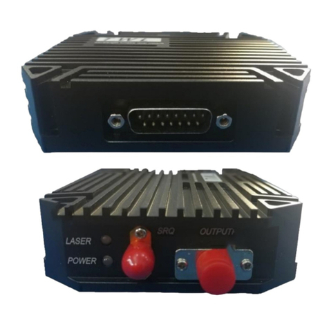
The Optilab NLFS-L-B is a L band narrow linewidth tunable laser.
The laser unit contains an external cavity laser diode and a low
noise laser driver. The NLFS-L-B provides up to 40 mW CW optical
power in the 1569 - 1608 nm wavelength region in a compact
design. The NLFS-L-B can be set to work at low noise mode, and
the laser linewidth width can be as narrow as sub-100 kHz. The
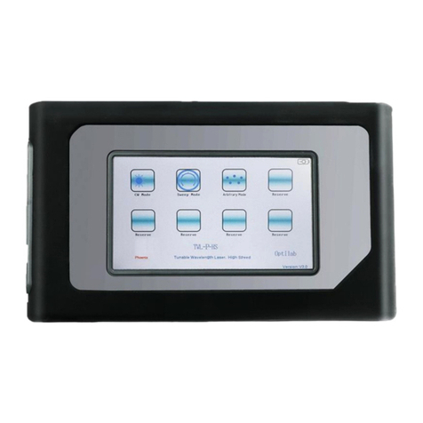
laser output can be controlled through the LCD touch screen or
remotely through a PC. Please contact Optilab for more
information.

NLFS-L-B User’s Manual
Page 2 of 13
Optilab, LLC
600 E. Camelback Road, Phoenix, AZ 85012
Phone: 1-602-343-1496, Fax: (602) 343-1489, Email: sales@oequest.com
1.4 Features
•External cavity laser diode
•Narrow linewidth
•1569 nm to 1608 nm tunable laser wavelength
•4 to 40 mW tunable laser output power
•LCD touch screen monitor and remote control
2. Operation
2.1 Introduction
This chapter describes how to operate the NLFS-L-B unit and
discusses the location and function of the controls and connectors.
2.2 Initial Inspection
Your NLFS-L-B rackmount was carefully inspected before it left the
manufacturer. It should be in proper working order upon receipt.
You should, however, inspect the unit for any damage that may
have occurred in transit. If the shipping container or the packing
material is damaged, keep it until the contents of the shipment
have been checked to be free of mechanical and electrical
damages. Notify Optilab, LLC promptly if any notable damage is
found.
Each NLFS-L-B shipment should include the following:
•NLFS-L-B laser benchtop unit
•Test Datasheet
•AC Power Cord
•USB cable
•Interlock
•Key Switch

NLFS-L-B User’s Manual
Page 3 of 13
Optilab, LLC
600 E. Camelback Road, Phoenix, AZ 85012
Phone: 1-602-343-1496, Fax: (602) 343-1489, Email: sales@oequest.com
2.3 Panel Control Interface
Feature
Function
1) Touch LCD
Screen
This LCD display and control the system setting and status.
Refer to Sec. 2.5 for operation instruction.
2) Optical OUT
Optical output port. The output pigtail uses a FC/APC
connector with endcap fiber. Mate this connector to a FC/APC
fiber connector.
3) Key Switch
Enable and disable the optical power.
4) Interlock
This BNC female connector is a safety interlock. It must be
shorted for the pump lasers to enable. Use the provided
accessory to short this port or connect it to a compatible
interlock device. If the interlock is open during normal
operation, the pump lasers will be turned off. To re-enable the
pump laser output, turn the key switch in the front panel to
“OFF” position first and start over.
5) AC Power Socket
and Switch
This receptacle accepts the electrical power input for the 100
to 240 V, 50 / 60 Hz AC power; the switch enables / disables
the AC electrical power to the rackmount unit.
6) USB
This USB port provides remote control feature. Refer to Sec.
2.6 for communication instruction.
7) Ethernet port
Not used on this model.

NLFS-L-B User’s Manual
Page 4 of 13
Optilab, LLC
600 E. Camelback Road, Phoenix, AZ 85012
Phone: 1-602-343-1496, Fax: (602) 343-1489, Email: sales@oequest.com
2.4 Turn On and OFF Operation Instructions
CAUTION!
Read and follow the SAFETY PRECAUTIONS in this manual before operation.
Failing to follow the instruction voids the warranty.
2.4.1 Turn on instruction
1. Provide proper placement of the benchtop to ensure the safety of the
device and the surrounding environment during operation. Wear
proper Personal Protective Equipment (PPE), such as gloves and
goggles rated for Class 3B Laser operation.
2. Launch the optical output pigtail. It can be connected to a fiber
collimator with FC/APC coupler, or mate to a matching end cap fiber
connector using a FC/APC adapter. In either case, thoroughly clean
and inspect the end fiber for any dust or contaminates that may ignite
upon operation.
3. Once all proper optical connections are made, plug in the AC power
cord into the rear panel. Ensure the front panel Main Laser Enable Key
is OFF, and the interlock on the back panel is connected properly.
4. Flip the rear panel Main Power Switch to the ON position to enable
power to the unit, which should enable the front panel LCD display.
5. Turn on the key switch on the front panel. Adjust the wavelength and
power level as needed on the touch screen. For narrow linewidth
application, turn on the low noise mode.
2.4.2 Turn off Instruction
Turn off the switch on the front panel to disable the laser output. Flip the rear
panel Main Power Switch to the OFF position.
Note: Do not hot-plug any optical patch cord or electrical cables. Permanent
damage may occur to the unit!
2.5 Touch Screen Operation
The benchtop unit uses the LCD touch screen for status monitoring
and system setting controls. Laser Information Page shows up
when the unit is powered on. Flip the Key in the front panel to the
ON position before setting the laser parameters.
1. Laser Information Page:
This page displays the status of the laser. Use the UP or DOWN button on
the right corner to select the setting item and use SET to enter the setting
item page. Use the INFO button to enter the system information page.

NLFS-L-B User’s Manual
Page 5 of 13
Optilab, LLC
600 E. Camelback Road, Phoenix, AZ 85012
Phone: 1-602-343-1496, Fax: (602) 343-1489, Email: sales@oequest.com
2. System Information Page
This page displays the information of the system. Use the triangle button
to turn on or off the back light, use the BACK button to return to the Laser
Information Page.
3. Wavelength Setting Page
This page offers the function to set the wavelength, it also displays the
minimum and maximum wavelength the laser can work at, the wavelength
setting resolution is 0.0001 nm. Use the SHIFT button to select the digit of
interest, use the INC to change the value of the digit, and then use the
SAVE button to save the settings. Wait 5 sec for the setting to be updated.
Use BACK button to return to the Laser Information Page.

NLFS-L-B User’s Manual
Page 6 of 13
Optilab, LLC
600 E. Camelback Road, Phoenix, AZ 85012
Phone: 1-602-343-1496, Fax: (602) 343-1489, Email: sales@oequest.com
4. Optical Power Setting Page
This page offers the function to set the laser power. It also displays the
minimum and maximum optical power the laser can output. The optical
power setting resolution is 0.01 dBm. Use the SHIFT button to select the
digit of interest, use the INC to change the value of the digit, and then use
the SAVE button to save the setting. Wait 5 sec for the setting to be
updated. Use the BACK button to return to the Laser Information Page.
5. Low Noise Mode Setting Page
This page offers the function to set noise mode. Press SHIFT to activate
the setting, then use INC button to set the low noise mode on or off, use
the SAVE button to save the setting. Wait 5 sec for the setting to be
updated.
Note: The laser outputs narrow linewidth only when Low Noise Mode is ON.
Note: Setting the Low Noise Mode to OFF each time when the laser is
powered on, then setting the Low Noise Mode to ON or OFF depends on the
requirement of the use.

NLFS-L-B User’s Manual
Page 7 of 13
Optilab, LLC
600 E. Camelback Road, Phoenix, AZ 85012
Phone: 1-602-343-1496, Fax: (602) 343-1489, Email: sales@oequest.com
2.6 Remote Control
For the standard NLFS-L-B, connecting the benchtop to an external
PC (installed with RS232 Serial Terminal software, i.e. Termite) will
allow for the parameter adjustment feature. Using a standard USB
cable to connect the USB port on the back panel on the benchtop
to the PC. Once the software is running, the benchtop unit will be
recognized as a COM port device. Use the Device Manager or
similar PC device tool to identify the COM port number. Once COM
port number is confirmed, check to see if the operating software
find the right device.
Use the following RS232 settings:
Baud Rate = 9600
Data Bits: 8
Stop Bits:1
Polarity: None
Append carrier return (CR) and line feed (LF) to each command.
The following commands can then be executed, with a corresponding
confirmation of the command afterwards (Syntax is CMD:XX, case sensitive)
Command
Description
Example
READ
Read the information of the SN,
Model type, and the driver
temperature
READ
READL
Read the status of the laser,
including wavelength, optical
power, LD temperature and
noise mode status
READL

NLFS-L-B User’s Manual
Page 8 of 13
Optilab, LLC
600 E. Camelback Road, Phoenix, AZ 85012
Phone: 1-602-343-1496, Fax: (602) 343-1489, Email: sales@oequest.com
SETLW
Set the Laser Wavelength
SETLW:XXXX.XXXX
XXXX.XXXX= wavelength in nm
SETLP
Set the Laser Power
SETLP:+XX.XX
+XX.XX= optical power in dBm
SETLN
Set the low noise mode ON or
OFF
SETLN:ON
ON = Low noise mode is ON
OFF= Low noise mode is OFF
3. Technical Specifications
Optical Specifications
Operating Wavelength
1569 nm to 1608 nm tunable
Optical Output Level
4 to 40 mW adjustable
Laser Linewidth (FWHM)
100 kHz typ., 200 kHz max.
Mechanical Specifications
Power Supply Requirements
100 to 240 VAC, 50/60 Hz
Optical Connectors
FC/APC
Output Fiber
Panda PM-15
Operating Temperature
10°C to +40°C (Standard)
Storage Temperature
-20°C to +70°C
Control
LCD touch screen, USB

NLFS-L-B User’s Manual
Page 9 of 13
Optilab, LLC
600 E. Camelback Road, Phoenix, AZ 85012
Phone: 1-602-343-1496, Fax: (602) 343-1489, Email: sales@oequest.com
4. Service and Support
4.1 Warranty
Optilab, LLC guarantees its NLFS-L-B unit to be free of defects for
1 year from the date of shipment. The guarantee does not cover
any damages resulting from the misuse or improper handling of the
equipment, or any incidental or consequential loss. Note that the
warranty will be void upon any attempt to open or to fix the
equipment by the user without prior approval of Optilab, LLC.
4.2 Service and Calibration
Your NLFS-L-B unit has been designed to provide years of trouble-
free operation. No internal maintenance is required provided that
the equipment is properly handled, operated, and kept away from
contamination. For any questions regarding the operation and
performance of the unit, please contact Optilab, LLC at:
Optilab, LLC
600 E. Camelback Road
Phoenix, AZ 85012
Phone: 1-602-343-1496
Fax: (602) 343-1489
Email: sales@oequest.com
4.3 Care of Fiber-optic Connectors
Damage to optical connectors account for more than 70 percent of
equipment performance degradation. To avoid such damage, the user
should use only industrial grade 99% pure isopropyl alcohol and follow
the procedures below to keep the connectors, adaptors, and receptacles
clean.
Cleaning Optical Connector End-face with Wipe and Alcohol
To properly clean optical connectors utilizing lens tissue grade wipes and alcohol
follow the procedure below. The moist wipe removes dust particles, oil and
contaminants that may damage or block the end-face of the connector during
connection. The dry wipe removes residual alcohol that may be ignited by optical
emission.
1. Disable the optical output and turn off unit to prevent accidental exposure or
damage to the optical connector by optical emission.
2. Moisten a wipe with alcohol by placing on top of the alcohol dispenser and
push down to saturate the wipe.

NLFS-L-B User’s Manual
Page 10 of 13
Optilab, LLC
600 E. Camelback Road, Phoenix, AZ 85012
Phone: 1-602-343-1496, Fax: (602) 343-1489, Email: sales@oequest.com
3. Place the moist wipe on a work surface and place a second dry wipe next to
it.
4. Wipe the optical connector, end-face down on the moist wipe 3 times and
then repeat on the dry wipe.
5. Visually inspect the end-face of the optical connector with an optical
microscope to verify cleanliness. Repeat steps 2 to 5 as needed.
Cleaning Optical Connector Sides, Receptacles, Adaptors with Swab and
Alcohol
Dust or particles can adhere to the insides of receptacles and adaptors or the sides
of the optical connector ferrule. Their presence can affect the alignment of the optical
fiber connectors and increase connection loss. To properly clean optical connectors,
receptacles, and adaptors utilizing a swab and alcohol follow the procedure below:
1. Disable the optical output and turn off unit to prevent accidental exposure or
damage to the optical connector by optical emission.
2. Moisten the swab by placing it on top of the alcohol dispenser and push down
to saturate the swab.
3. For receptacles, adapters, or other connection points, insert the moistened
swab and rotate the tip 1/2 turn clockwise and counterclockwise 6 times while
applying light but firm pressure.
4. For fiber connectors, rotate the tip of the moistened swab 5 revolutions
around the connector while applying light but firm pressure.
5. Visually inspect the end face of the connector with an optical microscope to
verify cleanliness. Clean end-face as needed.
Table of contents
Other OPTILAB Measuring Instrument manuals