Optimum M5 User manual

Operating Manual
Version 1.3.2
Thread cutting device
M5 - M12 / B16
Part no. 3352042

Version 1.3.2 vom 2023-3-21Page 2 Originalbetriebsanleitung
335 2042EN
1 Table of contents
1.1 Intended use .............................................................................................................................................3
1.2 Safety instructions ....................................................................................................................................3
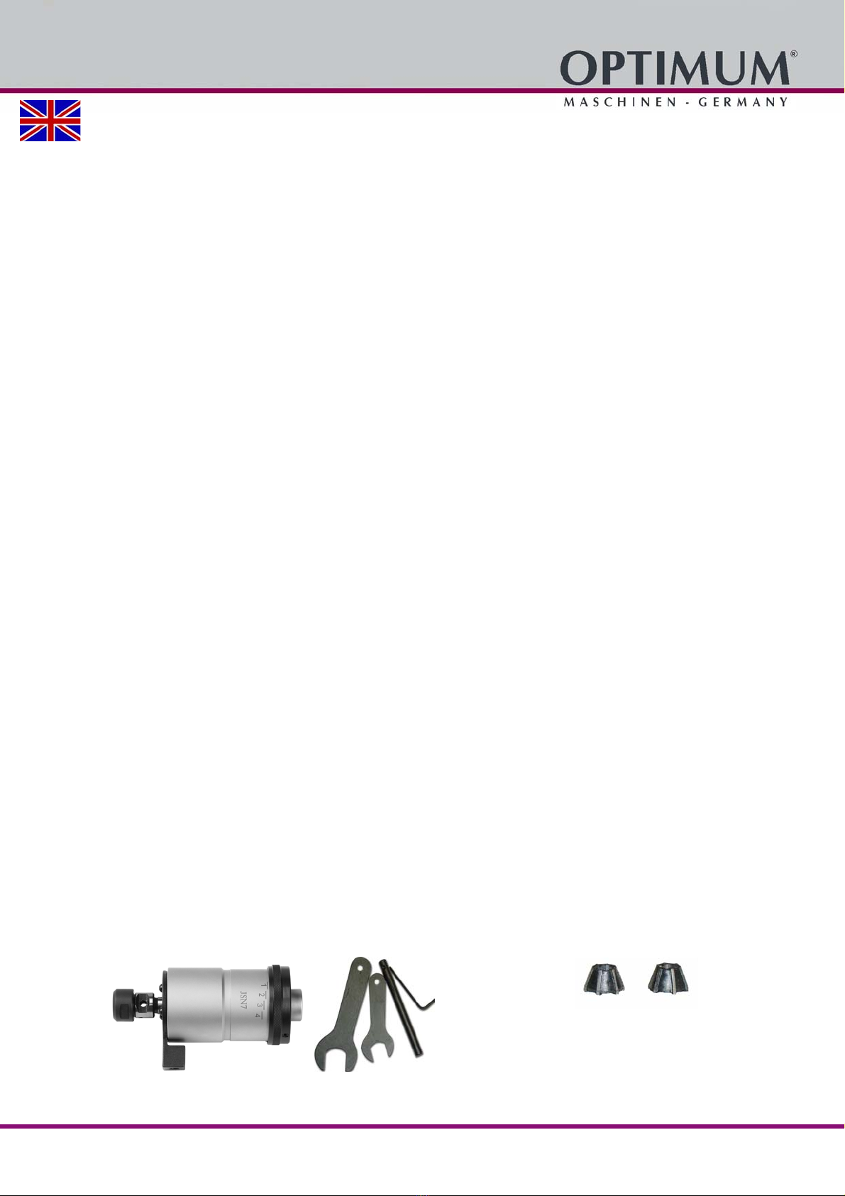
1.3 Scope of delivery ......................................................................................................................................3
1.4 Technical specification..............................................................................................................................4
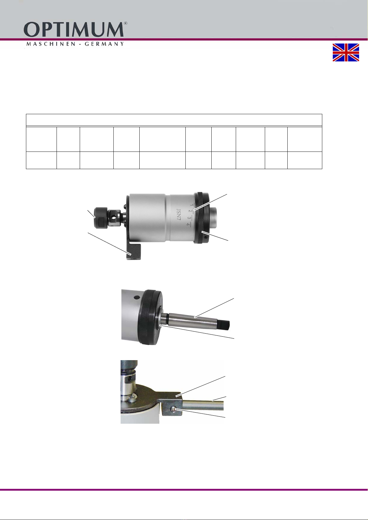
1.5 Structure ...................................................................................................................................................4
1.6 Assembly ..................................................................................................................................................4
1.7 Operation ..................................................................................................................................................5
1.8 Insert tap...................................................................................................................................................5
1.9 Torque adjustment....................................................................................................................................6
1.10 Maintenance and servicing .......................................................................................................................7
1.11 Change information operating manual......................................................................................................7
Preface
Dear customer,
Thank you very much for purchasing a product made by OPTIMUM.
OPTIMUM metal working machines offer a maximum of quality, technically optimum solutions and convince
by an outstanding price performance ratio. Continuous enhancements and product innovations guarantee
state-of-the-art products and safety at any time. Before commissioning the machine please thoroughly read
these operating instructions and get familiar with the machine. Please also make sure that all persons
operating the machine have read and understood the operating instructions beforehand. Keep these
operating instructions in a safe place nearby the machine.
Information
The operating instructions include indications for safety-relevant and proper installation, operation and
maintenance of the machine. The continuous observance of all notes included in this manual guarantee the
safety of persons and of the machine.
The manual determines the intended use of the machine and includes all necessary information for its
economic operation as well as its long service life. In the paragraph "Maintenance" all maintenance works
and functional tests are described which the operator must perform in regular intervals. The illustration and
information included in the present manual can possibly deviate from the current state of construction of your
machine. Being the manufacturer we are continuously seeking for improvements and renewal of the
products. Therefore, changes might be performed without prior notice. The illustrations of the machine may
be different from the illustrations in these instructions with regard to a few details. However, this does not
have any influence on the operability of the machine.
Therefore, no claims may be derived from the indications and descriptions. Changes and errors are reserved!
Your suggestion with regard to these operating instructions are an important contribution to optimising our
work which we offer to our customers. For any questions or suggestions for improvement, please do not
hesitate to contact our service department.
If you have any further questions after reading these operating instructions and you are not able to
solve your problem with a help of these operating instructions, please contact your specialised
dealer or directly the company OPTIMUM.
Optimum Maschinen Germany GmbH
Dr.- Robert - Pfleger - Str. 26
D-96103 Hallstadt, Germany
Fax (+49)0951 / 96555 - 888
Email: [email protected]
Internet: www.optimum-machines.com

Version 1.3.2 - 2023-3-21 3Translation of the original instructions
335 2042 EN
GSA_1_GB.fm
1.1 Intended use
Usage
The thread cutting device is mainly used for pillar drilling machines and bench drills.
The direction of rotation is changed via the integrated reversing gear by retracting the machine
spindle.
Advantages:
Time saving due to shorter cycle times.
Handling the machine with care.
Energy saving due to almost constant power consumption.
The prerequisite for using the thread cutting device is that it is mounted in a driven machine
spindle. After insertion into the machine, the retaining bar must be secured against twisting in
both directions of rotation. The thread cutting device is equipped with a length compensation in
tension and compression direction. This compensates for differences between spindle feed and
tap pitch. An overload clutch is integrated into the thread cutting device. The taps are picked up
and centred via flexible collets.
The torque generated during the thread cutting process is transmitted via adjustable and
floating driving cams.
The thread cutting device is not designed for internal coolant supply.
The thread cutting device is suitable for cutting right-hand and left-hand threads.
We will not be held liable for any damages resulting from any operation which is not in
accordance with the intended use.
1.2 Safety instructions
WARNING!
Before using the thread cutting device, make sure
that there is no danger to persons
and no damage to property.
Avoid any unsafe work methods:
Make sure that your operation does not create a safety hazard.
The rules specified in these operating instructions must be observed during assembly,
operation, maintenance and repair.
Do not work on the thread cutting device, if your concentration is reduced, for example,
because you are taking medication.
Observe the accident prevention regulations issued by your Employers Liability Insurance
Association or other supervisory authorities applicable to your company.
Inform the supervisor about all hazards or faults.
Use the prescribed personnel protective equipment. Wear tight-fitting clothes and a hair net
if necessary.
The instructions of the machine tool manufacturer still apply.
1.3 Scope of delivery
Thread cutting device
Tool:
2 Open-end spanner
1 Support bar
1 Allen key
Two flexible collets

Version 1.3.2 - 2023-3-214 Translation of the original instructions
335 2042
EN
GSA_1_GB.fm
INFORMATION
The thread cutting device is delivered without Morse taper shank. A required matching Morse
taper shank to the machine tool must be ordered separately.
Technical specification on page 4
1.4 Technical specification
1.5 Structure
Img.1-1: Structure of the thread cutting device
1.6 Assembly
Clean the receptacle on the
thread cutting device and on
the shank.
Insert the shaft into the
receptacle.
Img.1-2: Shaft assembly
CAUTION!
The grub screw must be
turned completely into the
holder of the holding rod.
Align position of countersink
with position of grub screw.
Img.1-3: Mounting support bar
Fix the shaft with a light tap with a plastic hammer.
Slide the support bar into the receptacle.
Fix the holding rod with the grub screw.
Thread cutting device M5 - M12
Disengage-
ment path
Free
wheel-
ing
Length com-
pensation on
tension
Max.
Speed
Transmission ratio
forward and return
Cutting
area
Clamp-
ing range
Shaft
receptacle Length
Length com-
pensation
under pres-
sure
4 mm 1.5 mm 8.5 mm 200 rpm 1 : 1.75 M5 - M12 3.5-10 B16
DIN 238 156 mm 5 mm
Torque adjustment ring
Universal clamping head
Torque adjustment scale
Mounting support bar
Shaft
Shaft receptacle
Mounting support bar
Support bar
Grub screw

Version 1.3.2 - 2023-3-21 5Translation of the original instructions
335 2042 EN
GSA_1_GB.fm
CAUTION!
The machine tool must be secured against
restarting when the thread cutting device is
mounted. Follow the instructions of the
machine tool manufacturer.
Img.1-4: Securing assembly
Mount the thread cutting device in the receptacle of the machine spindle.
Secure the support bar against twisting in both directions.
Ensure free guidance of the support bar for the entire spindle travel.
1.7 Operation
INFORMATION
This device is intended for use on drilling machines without a tapping device with
automatic reversal of the direction of rotation. The speed of the machine used for thread
cutting should therefore be kept as low as possible, but not exceed 200 rpm.
Manual retraction of the drilling sleeve in time to reverse the direction of rotation of the
tapping attachment is hardly possible if the speed of the drilling machine is too high.
The slipping clutch is active for too long and thus heats up too quickly and too much.
1.8 Insert tap
The tap is clamped by
adjustable and floating drive
cams. The tap is centred via
the collet chuck.
Unscrew the clamping nut
from the thread cutting
device.
Place the required collet in
the clamping nut.
Screw the clamping nut with collet onto the thread of
the clamping head
Push the tap into the collet.
Tighten the clamping nut firmly using an open-ended
spanner.
Img.1-5: Tap installation
The integrated overload clutch interrupts the torque transmission between machine spindle and
tap during the tapping process if the set torque is exceeded. This protects the tap from damage.
WARNING!
Torque adjustment may only be carried out when the machine is switched off.
The torque setting depends on various factors, e.g. speed, material, lubrication. Therefore, no
torque values can be given.
Mounting
support bar
Drilling column
Thread of the
clamping head
Collet
Tension nut

Version 1.3.2 - 2023-3-216 Translation of the original instructions
335 2042
EN
GSA_1_GB.fm
1.9 Torque adjustment
Loosen the grub screw in the
torque adjustment ring.
Set the torque adjustment ring
to the lowest torque value (turn
clockwise as far as it will go).
Make a test thread before you
start cutting a larger number of
threads.
Img.1-6: Overload clutch
If the clutch slips. Increase the torque via the adjusting ring and fix the setting by tightening
the grub screw.
Cut the thread again.
Reduce torque turn clockwise.
Increase torque turn counterclockwise.
After reaching the thread depth, retract the tool spindle. The spindle of the tapping
attachment reverses the running direction.
After leaving the cut thread, the tapping attachment automatically switches back to the previous
direction of rotation.
ATTENTION!
When retracting the tool spindle, make sure that the length compensation is not pulled
out completely on tension. Avoid jerky retraction of the spindle.
The direction of rotation is changed in counterclockwise rotation (left-hand thread) and
clockwise rotation (right-hand thread).
Torque adjustment ring
Grub screw
Free
wheeling
Spindle
feed stop
Start Reverse motion

Version 1.3.2 - 2023-3-21 7Translation of the original instructions
335 2042 EN
GSA_1_GB.fm
1.10 Maintenance and servicing
Clean the tapping attachment with a hand cloth.
Do not use aggressive solvents.
Do not use fibrous materials.
The thread apparatus is not lubricated.
Spray or rub the tapping attachment with a preservative oil to prevent rusting and to
preserve the running of the tapping attachment.
Remove all coolant residues and machining residues before storage.
1.11 Change information operating manual
Chapter Short summary new version number
1.9 Layout change ; Change of the direction of rotation
also in counterclockwise and clockwise rotation.
1.3.1
1.4 ; 1.7 Technical data, Maximum speed to 200 rpm ;
Operation
1.3.2

Version 1.3.2 2023-03-21 8 Originalbetriebsanleitung
335 2042DE | EN
2 Ersatzteilzeichnung - Spare parts drawing
Teileliste
Pos.
Bezeichnung Designation Menge Grösse Artikelnummer
Qty. Size Item no.
1 Haltering Guard ring 1 033520421
2 Gewindestift Thread pin 1 DIN 916 - M6 x 8 033520422
3 Haltestange Support rod 1 033520423
4 Axial-Nadellager Axial needle bearing 1 AXK 3047 033520424
5 Auflagering Supporting ring 1 033520425
6 Einstellring Adjusting ring 1 033520426
7 Messingstift Brass pin 1 033520427
8 Gewindestift Thread pin 1 DIN 915 - M6 x 8 033520428
9 Gehäuse Housing 1 033520429
10 Sicherungsring Snap ring 1 DIN 471 - 26 x 1.2 0335204210
11 Feder Spring 1 0335204211
12 Stellring Drehmoment komplett Tension ring torque complete 1 0335204212
12-1 Stellring Tension ring 1
12-2 Distanzscheibe Spacer ring 1
12-3 Stahlkugel Steel ball 12
12-4 Kugelring Ball ring 1
12-5 Distanzscheibe Spacer ring 1
13 Rillenkugellager Grooved ball bearing 1 6007 0335204213
14 Zylinderstift Cylindrical pin 1 ISO 8734 - 5 x 18 - A 0335204214
15 Sicherungsring Snap ring 1 GB 893.1 - 65 0335204215
31
36
38
3
2
1
34
33
32
23
19
20
22
35
21
17
18
16
25
24 26
27
28
29
42
39
30
15
37
11
9
14
4
8
7
6
10
40
5
41
13
12-1
12-2
12-3
12-4
12-5

Version 1.3.2 2023-03-21 9Originalbetriebsanleitung
335 2042 DE | EN
16 Vierkanthülse Square case 1 0335204216
17 Welle Shaft 1 0335204217
18 Sicherungsring Snap ring 1 DIN 471 - 14 x 1 0335204218
19 Klemmstück Linksgewinde Clamping piece, left-hand thread 1 0335204219
20 Klemmstück Rechtsgewinde Clamping piece, right-hand thread 1 0335204220
21 Spannstift 1 ISO 13337 - 2 x 8 0335204221
22 Schraube Links-Rechtsgewinde Screw, left- right hand tread 1 0335204222
23 Rillenkugellager Grooved ball bearing 1 61909 0335204223
24 Zahnradhalter Gear wheel holder 1 0335204224
25 Buchse Bushing 1 0335204225
26 Zahnrad Gear wheel 3 0335204226
27 Zylinderstift Cylindrical pin 3 ISO 2338 - 5 h8 x 18 0335204227
28 Distanzscheibe klein Spacer ring, small 1 0335204228
29 Distanzscheibe gross Spacer ring, large 1 0335204229
30 Inneres Zahnrad Inner gear wheel 1 0335204230
31 Spannmutter Clamping nut 1 0335204231
32 Lagerabdeckung Bearing cover 1 0335204232
33 Sicherungsring innen Snap ring, inside 1 0335204233
34 Sicherungsring außen Snap ring, outside 1 0335204234
35 Sicherungsscheibe Snap ring 1 DIN 6799 - 5 0335204235
36-1 Flexible Spannzange klein Flexible clamping ring, small 1 03352042361
36-2 Flexible Spannzange groß Flexible clamping ring, large 1 03352042362
37 Distanzscheibe Spacer ring 1 0335204237
38 Linsenkopfschraube Round head screw 3 ANSI B18.3.4M - M5 x 0.8 x 10 0335204238
39 Feder Spring 1 0335204239
40 Feder Spring 9 0335204240
41 Feder Spring 9 0335204241
42 Feder Spring 1 0335204242
Teileliste
Pos.
Bezeichnung Designation Menge Grösse Artikelnummer
Qty. Size Item no.

Version 1.3.2 2023-03-21 10 Originalbetriebsanleitung
335 2042DE | EN
This manual suits for next models
3
Table of contents
Popular Cutter manuals by other brands

Alamo
Alamo Grizzly 52 Operator's manual

Summa
Summa S CLASS user manual

Dahle
Dahle 440 operating instructions

Wolfcraft
Wolfcraft LC 100 Translation of the original operating instruction

Batavia
Batavia MAXXSERIES JBJ-XG01 operating instructions

Martin Yale
Martin Yale GC10 Installation, operation and maintanance manual

Grizzly
Grizzly 303 500 Operator's instruction manual

Gude
Gude GF 383 Translation of the original instructions

Jula
Jula 243-007 operating instructions

Reliable
Reliable End Cutter With 96" Track & Lifter Set... Specifications

Rayjet
Rayjet 8015 Service manual

SIRI
SIRI SIRIPRO 57 Operating and maintenance manual