OPTRONIC LVMC User manual

Interface A2, Release Date: 02.03.2022
Page 1
LVMC User Manul A2 - 499.027.82
OPTRONIC AG
SWITZERLAND
Unteregger Strasse 53
CH-9403 Goldach
Phone: +41 (0)71 844 02 00
Fax: +41 (0)71 844 02 10
e-mail: support@optronic.ch
web: www.optronic.ch
LVMC
Digital Light Curtain
for Detecting, Counting, Measuring, and Classifying
User Manual
Interface A2

Interface A2, Release Date: 02.03.2022
Page 2
LVMC User Manul A2 - 499.027.82
OPTRONIC AG
SWITZERLAND
Unteregger Strasse 53
CH-9403 Goldach
Phone: +41 (0)71 844 02 00
Fax: +41 (0)71 844 02 10
e-mail: support@optronic.ch
web: www.optronic.ch
© 2021 OPTRONIC AG
All rights to text and images reserved.
It is not permitted to reproduce this user manual or parts thereof without the permission of OPTRONIC AG.
Without the permission of OPTRONIC AG, the use of this user manual for other than personal purposes is
prohibited by copyright law.

Interface A2, Release Date: 02.03.2022
Page 3
LVMC User Manul A2 - 499.027.82
OPTRONIC AG
SWITZERLAND
Unteregger Strasse 53
CH-9403 Goldach
Phone: +41 (0)71 844 02 00
Fax: +41 (0)71 844 02 10
e-mail: support@optronic.ch
web: www.optronic.ch
Table of Contents
1Safety................................................................................................................................................................. 7
1.1 Intended Use ............................................................................................................................................ 7
1.2 Safety Instructions................................................................................................................................... 7
1.2.1 General Safety Instructions to Protect Against Physical Damage ................................................... 7
1.2.2 General instructions to Avoid Damage to the Device........................................................................ 7
2Overview ............................................................................................................................................................ 8
3Get Started Right Away - The Quick Start........................................................................................................ 9
3.1 Device Selection....................................................................................................................................... 9
3.1.1 Selection of the Dimension ................................................................................................................. 9
3.1.2 Connectors, Status LED and Toggle Switch....................................................................................... 9
3.2 Software ................................................................................................................................................... 9
3.2.1 Downloading ......................................................................................................................................10
3.2.2 Installing.............................................................................................................................................10
3.3 Power Supply .........................................................................................................................................10
3.3.1 Supplying Power via D-Sub Connector.............................................................................................10
3.3.2 Supplying power with PoE via Ethernet............................................................................................10
3.4 Readiness...............................................................................................................................................10
3.5 Establishing a Connection.....................................................................................................................11
3.5.1 Via USB...............................................................................................................................................11
3.5.2 Via Ethernet........................................................................................................................................ 11
3.5.3 Operation............................................................................................................................................12
3.6 Counting Objects ...................................................................................................................................13
3.7 Modifying Settings.................................................................................................................................14
3.8 Monitoring via Web Browser................................................................................................................. 15
4Operation of the LVMC ...................................................................................................................................16
4.1 Sensing Area .......................................................................................................................................... 16
4.2 Operating Modes ................................................................................................................................... 16
4.3 Access Levels ........................................................................................................................................ 16
4.4 Counting Channels................................................................................................................................. 17
4.5 Minimum Required Passing Time / Oversampling..............................................................................17
4.6 Maximum Permissible Passing Time / Stuck Objects ........................................................................18
4.7 Minimum Required Object Size.............................................................................................................18
4.8 Sensing Area Static Coverage...............................................................................................................18

Interface A2, Release Date: 02.03.2022
Page 4
LVMC User Manul A2 - 499.027.82
OPTRONIC AG
SWITZERLAND
Unteregger Strasse 53
CH-9403 Goldach
Phone: +41 (0)71 844 02 00
Fax: +41 (0)71 844 02 10
e-mail: support@optronic.ch
web: www.optronic.ch
4.9 Manual Calibration of the Sensing Area...............................................................................................18
4.10 Object Detection Methods.....................................................................................................................19
4.11 Automatic Mode ....................................................................................................................................20
4.12 Monitoring Signals.................................................................................................................................21
4.12.1 Signal „Monitoring 1“: (Pollution-) Warning .................................................................................21
4.12.2 Signal „Monitoring 2“: Operational Readiness.............................................................................21
4.13 Digital Inputs and Outputs.....................................................................................................................21
4.14 External Channel Selection via Digital Inputs or Toggle Switch..........................................................22
4.14.1 Channel Selection via Digital Inputs.............................................................................................22
4.14.2 Channel Selection via Toggle Switch ...........................................................................................22
4.15 Configuration of the Inputs and Outputs..............................................................................................23
4.16 Timer.......................................................................................................................................................25
4.17 Speed Measurement.............................................................................................................................. 25
4.18 Date and Time........................................................................................................................................25
4.19 Analysis Function...................................................................................................................................26
4.20 Histogram and Statistical Data.............................................................................................................26
4.21 Error Log.................................................................................................................................................26
4.22 Measurement Inaccuracy and Repeat Accuracy .................................................................................27
4.23 Configuration Sets .................................................................................................................................28
4.24 Communication via USB........................................................................................................................28
4.25 Communication via Ethernet.................................................................................................................28
4.26 Power Supply .........................................................................................................................................28
4.27 Visual Status Indication via Sensor Light.............................................................................................29
4.28 Visual Status Indication via Status LED................................................................................................29
5LVMC CMT –LVMC Configuration and Monitoring Tool.............................................................................30
5.1 Requirements.........................................................................................................................................30
5.2 Interface Compatibility ..........................................................................................................................30
5.3 Installing the Software...........................................................................................................................31
5.4 Uninstalling the Software ......................................................................................................................31
5.5 Build-Up of the Software........................................................................................................................31
5.6 Access Levels ........................................................................................................................................ 32
5.7 Units of Inputs and Outputs ..................................................................................................................32
5.8Menus.....................................................................................................................................................33
5.8.1 Menu „File“ .........................................................................................................................................33
5.8.2 Menu „Communication“ ....................................................................................................................35
5.8.3 Menu „Test“........................................................................................................................................35

Interface A2, Release Date: 02.03.2022
Page 5
LVMC User Manul A2 - 499.027.82
OPTRONIC AG
SWITZERLAND
Unteregger Strasse 53
CH-9403 Goldach
Phone: +41 (0)71 844 02 00
Fax: +41 (0)71 844 02 10
e-mail: support@optronic.ch
web: www.optronic.ch
5.8.4 Menu „Miscellaneous“.......................................................................................................................36
5.8.5 Menu „Help“ .......................................................................................................................................40
5.9 Establishing a Connection with a LVMC ..............................................................................................41
5.10 Configuration Page................................................................................................................................42
5.10.1 Section “Ethernet Configuration”..................................................................................................43
5.10.2 Section “Sensor Configuration” ....................................................................................................44
5.10.3 Section “Automatic Mode Configuration”....................................................................................47
5.10.4 Section “Channel Configuration” ..................................................................................................48
5.10.5 Section „I/O Configuration”...........................................................................................................50
5.10.6 Buttons...........................................................................................................................................54
5.11 Status Page............................................................................................................................................55
5.11.1 Section “General Status Information” ..........................................................................................56
5.11.2 Section “Ethernet State”................................................................................................................ 57
5.11.3 Section “Channel Status” ..............................................................................................................57
5.11.4 Section “Output Counter Reading” ...............................................................................................58
5.11.5 Section “Timer Status” ..................................................................................................................58
5.11.6 Buttons...........................................................................................................................................59
5.12 Analysis Page.........................................................................................................................................60
5.12.1 Captured Sensor Image ................................................................................................................61
5.12.2 Section “Last Object”.....................................................................................................................62
5.12.3 Section “All Objects”......................................................................................................................62
5.12.4 Section “Continuous Data”............................................................................................................63
5.12.5 Section “Settings”..........................................................................................................................63
5.12.6 Section “Sensor Image Capturing” ............................................................................................... 65
5.12.7 Buttons...........................................................................................................................................65
5.13 Statistics & Automatic Page .................................................................................................................66
5.13.1 Section “Histogram”......................................................................................................................67
5.13.2 Section “Statistics Data” ...............................................................................................................67
5.13.3 Section “Automatic Mode Data”...................................................................................................68
5.13.4 Buttons...........................................................................................................................................68
5.14 Error Log Page ....................................................................................................................................... 69
5.14.1 Buttons...........................................................................................................................................70
5.15 Display of the LVMC Properties............................................................................................................70
5.15.1 Button.............................................................................................................................................71
5.16 Set Optocoupler Outputs Test Function...............................................................................................72
5.16.1 Section “Output x: OC State”.........................................................................................................72

Interface A2, Release Date: 02.03.2022
Page 6
LVMC User Manul A2 - 499.027.82
OPTRONIC AG
SWITZERLAND
Unteregger Strasse 53
CH-9403 Goldach
Phone: +41 (0)71 844 02 00
Fax: +41 (0)71 844 02 10
e-mail: support@optronic.ch
web: www.optronic.ch
5.16.2 Buttons...........................................................................................................................................72
5.17 Optocoupler Outputs Frequency Test...................................................................................................73
5.17.1 Section “Output x: Frequency Test”..............................................................................................73
5.17.2 Section “Loop Counter”.................................................................................................................73
5.17.3 Section “Frequency Selection”......................................................................................................74
5.17.4 Buttons...........................................................................................................................................74
5.18 Hints & Error Messages.........................................................................................................................75
6HTTP Server –Access by Web Browser .......................................................................................................76
7LVMC RC - Remote Control via Ethernet .......................................................................................................82
8Dimensions & Mounting ................................................................................................................................85
9Sensing Area End Section ..............................................................................................................................85
10 Part Name................................................................................................................................................... 86
11 Part Number ............................................................................................................................................... 87
12 Available Dimensions / Minimum Object Size ......................................................................................... 88
13 Replacement for a Light Curtain LV…M ....................................................................................................89
14 Connection Diagram D-Sub Connector.....................................................................................................90
14.1 Embodiment WS: Toggle Switch and 3 Digital Outputs ...................................................................... 91
14.2 Embodiment DI: 3 Digital Outputs and 2 Digital Inputs .......................................................................92
14.3 Embodiment DO: 5 Digital Outputs .......................................................................................................93
14.4 Embodiment DIO: 3 Digital Outputs and 2 Digital I/Os........................................................................94
15 Electrical Characteristics...........................................................................................................................95
16 Operating Conditions.................................................................................................................................95
17 Limit Values for the Detection of Objects ................................................................................................95
18 System Requirements for CMT.................................................................................................................96

Interface A2, Release Date: 02.03.2022
Page 7
LVMC User Manul A2 - 499.027.82
OPTRONIC AG
SWITZERLAND
Unteregger Strasse 53
CH-9403 Goldach
Phone: +41 (0)71 844 02 00
Fax: +41 (0)71 844 02 10
e-mail: support@optronic.ch
web: www.optronic.ch
1Safety
1.1 Intended Use
The LVMC digital light curtain is a sensor for detecting, counting, measuring and classifying arbitrary objects.
Use the device only for the purpose stated in this documentation. At any time, the light curtain may only be
used within the limits of the prescribed and specified technical data and operating conditions.
The light curtain is particularly not suitable for subsequent applications: Under water, in potentially explosive
areas, in hot (more than +50°C) or cold (less than 0°C) areas, in condensing humidity, and in areas with flying
sparks.
The light curtain must not be used in safety applications, in particular not to protect against personal injury. It
must not be used as a safety component in accordance with the EU Machinery Directive.
In the event of improper use, modification or manipulation, any warranty is void, and any responsibility and
liability of OPTRONIC AG for any damage or consequential loss caused thereby is excluded.
Only use original OPTRONIC AG accessories or accessories recommended by OPTRONIC AG. Read the rele-
vant documentation carefully before putting the device into operation.
The operator of the system in which the light curtain is integrated is responsible for compliance with national
and international safety and accident prevention regulations (e.g. EN292, EN60204).
1.2 Safety Instructions
1.2.1 General Safety Instructions to Protect Against Physical Damage
The instructions for the power supply must be observed. No other type of power supply than that described
in this manual may be used
All cables must be routed in such a way that nobody can step on them or trip over them
Work on electrical equipment poses a safety risk and must be specially secured. The light curtain may there-
fore only be installed and connected by a specialist in a voltage-free state. During this time, the machine
must be switched off and secured against being switched on again.
1.2.2 General instructions to Avoid Damage to the Device
In case of faulty connection with other devices or a faulty power supply, there is a risk that the light curtain
will be damaged. Read the relevant instructions before establishing the connection and read the documenta-
tion before commissioning.

Interface A2, Release Date: 02.03.2022
Page 8
LVMC User Manul A2 - 499.027.82
OPTRONIC AG
SWITZERLAND
Unteregger Strasse 53
CH-9403 Goldach
Phone: +41 (0)71 844 02 00
Fax: +41 (0)71 844 02 10
e-mail: support@optronic.ch
web: www.optronic.ch
2Overview
The digital light curtain LVMC is used for detecting, counting, measuring and classifying arbitrary objects. It
has a gapless sensing area for position and orientation independent registration of passing objects. With a
suitable parameterization, even complicated shapes (spiral springs, rings, partially translucent objects, etc.)
do not lead to multiple counts. The device, which is available in various sensing area dimensions, can reliably
detect balls with a minimum diameter of 1mm. Objects that are permanently within the sensing area (con-
veyors, machine parts, etc.) can be faded out by specifying a statically covered area. The light curtain LVMC
offers four independent counting channels for simultaneous detection of different objects. Selectively, the
device classifies passing objects by automatically assigning them to a channel. The integrated automatic
function learns independently by continuously analyzing objects passing the sensing area. Based on the
learned information, the light curtain is automatically reconfigured at runtime, so that faulty objects, for ex-
ample, can be sorted out without user intervention. For problem analysis and parameterization, a large num-
ber of helpful measured values are displayed. Detected objects are visualized in a two-dimensional picture.
The integrated statistics function collects statistical data and illustrates it in a histogram. Two high-
resolution timers (the maximum resolution is 30us) enable to capture the time interval between two events.
In this way, for example, the speed of an object can be determined by connecting two light curtains in series.
Continuous contamination of the optics, the transmission and reception power of the sensing area, as well
as changes in lighting conditions and temperature are continuously monitored and automatically taken into
account during operation. Correct functioning of hardware and software is continuously monitored. Objects
stuck in the sensing area can be detected by specifying the maximum permitted passing time. By means of
configurable oversampling, the suppression of interferences (electromagnetic fields, light flashes, vibrations,
etc.) can be optimized by increasing the minimum possible object passing time. Occurred errors that are
preserved when power is turned off and can be read out at any time.
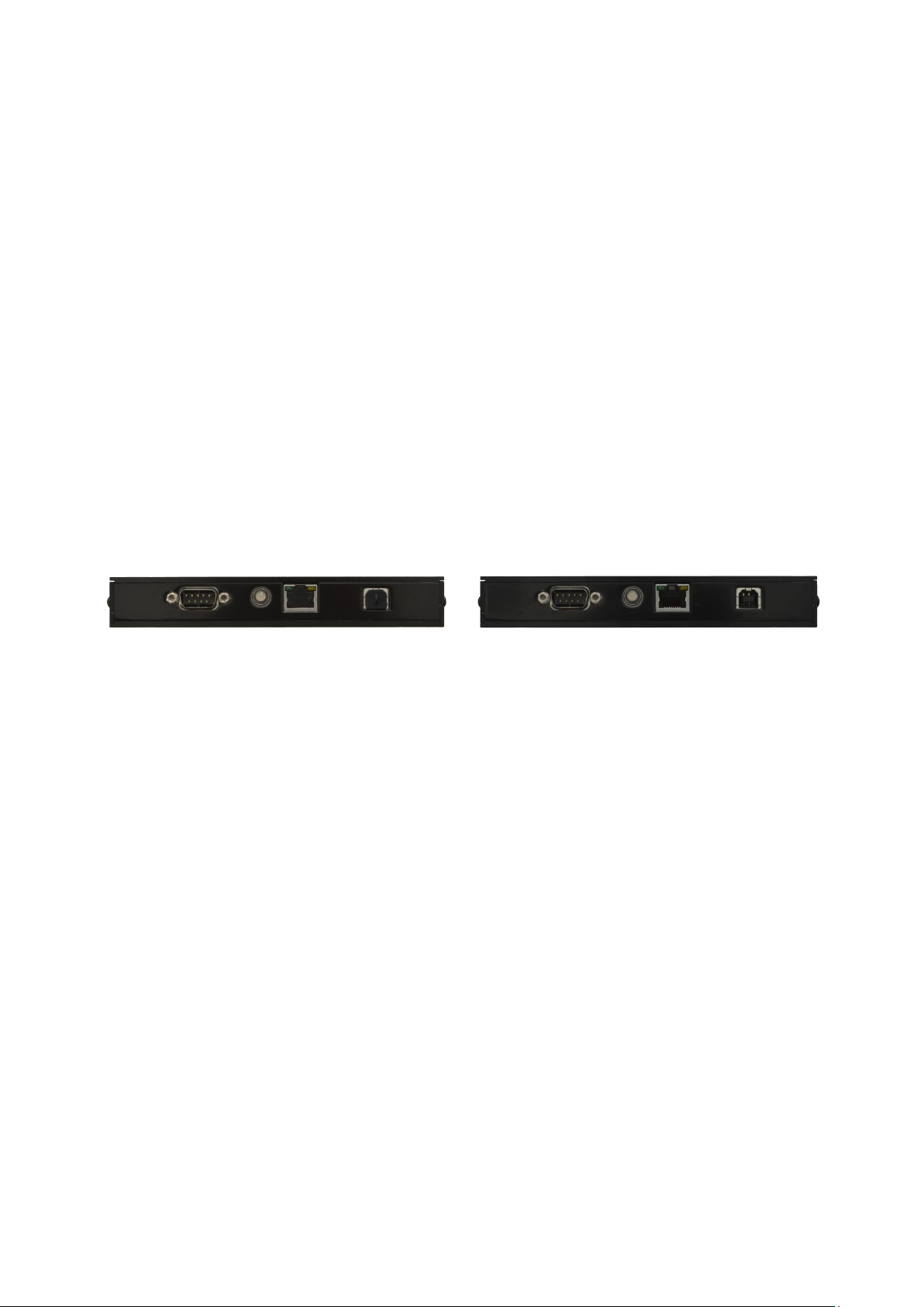
For communication with the outside world, the device is equipped with galvanically isolated optocoupler
inputs and optocoupler outputs (available on a 9 pin D-Sub connector), an USB interface, and an Ethernet
interface. The light curtain also offers a three-color status LED for quick determination of the status or, alter-
natively, a toggle switch for channel selection. How many optocoupler inputs and outputs are available de-
pends on the device type. Overall, a total of five signal lines are available, their assignment is configurable.
For example, counting and status information can be supplied in real time via the optocoupler outputs and,
via the optocoupler inputs, a channel can be selected, the automatic function can be restarted, or a timer can
be stopped.
Configuration, operation, analysis and monitoring of the always independently operating light curtain is done
by use of the Microsoft Windows-based software LVMC CMT ("LVMC Configuration and Monitoring Tool").
The CMT can address the LVMC via USB and Ethernet. Beside this, it is possible to remotely control the de-
vice via Ethernet. The configuration and the status of the device can be retrieved by use of a web browser.
For security reasons, communication via Ethernet is always encrypted.
The Ethernet interface can be configured statically or dynamically by DHCP. The clock integrated in the
LVMC is reset when power is turned off, but date and time can be synchronized by use of a NTP server via
the Ethernet network.
Power is supplied to the device by 24V DC via the D-Sub connector, or can alternatively be implemented by
Power over Ethernet (PoE).

Interface A2, Release Date: 02.03.2022
Page 9
LVMC User Manul A2 - 499.027.82
OPTRONIC AG
SWITZERLAND
Unteregger Strasse 53
CH-9403 Goldach
Phone: +41 (0)71 844 02 00
Fax: +41 (0)71 844 02 10
e-mail: support@optronic.ch
web: www.optronic.ch
3Get Started Right Away - The Quick Start
The aim of this chapter is to help you get started using the LVMC. It shows how you can proceed step by step
to capture the first objects as quickly as possible.
3.1 Device Selection
3.1.1 Selection of the Dimension
The first choice to make concerns the dimension of the sensing area. It should be selected as small as pos-
sible, but minimally in such a manner, that no object penetrates the sensing area close to an edge or even
touches the boundary. Since the minimum object size that can be detected by the LVMC also depends on the
dimension of the sensing are, this size must also be taken into account. See Chapter 8 for information on
dimensions, and Chapter 12 for information on available dimensions and associated minimum object sizes.
3.1.2 Connectors, Status LED and Toggle Switch
Each LVMC is equipped with a D-Sub connector, which is equipped with digital outputs and possibly digital
inputs and which can be used to supply power. In addition, the device offers an USB port for communication
with a PC running Microsoft Windows, as well as an Ethernet port to integrate it into an Ethernet network and
to supply power via Power over Ethernet (PoE). On delivery, the USB and the Ethernet port are protected with
a cap against contamination. They can be removed manually. Depending on the version, a toggle switch or a
three-color status LED is integrated. All these elements are located on the front of the device:
The three-color status LED provides information about the current device status. It is statically green when
the device is ready for object detection. If there is an object in the sensing area, it will be static blue. If the
maximum permitted passing time of an object in the sensing area is exceeded, the LED flashes red-blue. A
static red LED indicates that an error is pending. It flashes red, when the LVMC has been stopped by the user,
for example, for configuration.
Each LVMC is equipped with at least three digital outputs on the D-Sub connector: Output 1 is permanently
assigned to the readiness signal "Monitoring 2", outputs 2 and 3 are freely configurable. Whether the light
curtain has two additional inputs, outputs, or dynamically configurable inputs/outputs depends on the design
variant.
Chapter 10 describes how the part number can be determined based on the dimension and the design vari-
ant. Chapter 11 explains the structure of the assigned part number.
3.2 Software
The Microsoft Windows based software suite LVMC CMT is used for configuration, operation, analysis and
monitoring of the light curtain It is available in several versions to match the interface version of the firmware
of your LVMC. The interface version is labeled with a capital letter followed by a numeral. It changes when
essential new functions have been integrated into the firmware, resulting in changes in the interface between
the LVMC firmware and the CMT. This document refers to the interface version A2.

Interface A2, Release Date: 02.03.2022
Page 10
LVMC User Manul A2 - 499.027.82
OPTRONIC AG
SWITZERLAND
Unteregger Strasse 53
CH-9403 Goldach
Phone: +41 (0)71 844 02 00
Fax: +41 (0)71 844 02 10
e-mail: support@optronic.ch
web: www.optronic.ch
3.2.1 Downloading
The installation file can be downloaded from the OPTRONIC homepage www.optronic.ch in section „DOWN-
LOAD“. Take the latest version with the highest version number that matches the interface version of your
LVMC. If you do not know the interface version, select the most recent one, i.e. the one with the letter furthest
back in the alphabet and the highest numeral. If the software does not match your LVMC, it will tell you as
soon as you try to connect to the LVMC.
Alternatively, you can download the appropriate file for interface versions A1 and A2, which are available at
the time of this document's completion, directly from one of the following links:
Interface version A1: http://www.optronic.ch/downloads/sensors/lvmc/cmt/lvmc_cmt_a1_latest_setup.exe
Interface version A2: http://www.optronic.ch/downloads/sensors/lvmc/cmt/lvmc_cmt_a2_latest_setup.exe
Any number of software versions can be installed on your PC at the same time.
3.2.2 Installing
Install the software on your PC by running the installer. The installer will guide you through the
installation so that it should be completed in a few seconds. If you are not logged in with ad-
ministrator rights on your PC, the installer will ask you to enter the administrator password.
During installation, you will be asked if you want to create a desktop icon. Decide for it, so that
you can start the software later comfortably by a double-click on the thereby created new icon
on your desktop.
3.3 Power Supply
Now the LVMC must be supplied with power. This can be done in two ways: Via the D-Sub connector or via
the Ethernet port.
3.3.1 Supplying Power via D-Sub Connector
For the supply via the D-Sub plug, you need a 24V DC power supply as well as a connection cable with 9-pin
D-Sub socket. Make the wiring as described in Chapter 14.
3.3.2 Supplying power with PoE via Ethernet
If you have an Ethernet switch with Power over Ethernet (PoE) functionality, you can power the LVMC directly
from this switch. To do this, connect a free PoE port to the Ethernet port of the LVMC via a network cable.
3.4 Readiness
The green status LED on the front panel indicates that the LVMC is ready for operation. The light curtain is
now ready to detect objects. If the LED remains dark, please check the power supply first. If it is red, an error
is pending. Make sure that the sensing area is free.

Interface A2, Release Date: 02.03.2022
Page 11
LVMC User Manul A2 - 499.027.82
OPTRONIC AG
SWITZERLAND
Unteregger Strasse 53
CH-9403 Goldach
Phone: +41 (0)71 844 02 00
Fax: +41 (0)71 844 02 10
e-mail: support@optronic.ch
web: www.optronic.ch
3.5 Establishing a Connection
3.5.1 Via USB
Connect the LVMC to your PC using a standard USB 2.0 cable (USB A to USB B).
Start the CMT software by double-clicking on the newly created icon
on the desktop, or start the program via the start menu. Select
entry “Connect to LVMC by USB” in menu “Communication” of the
CMT. The connection to the LVMC should be established immediately.
3.5.2 Via Ethernet
Connect the LVMC to your Ethernet network using an Ethernet cable, if this is not already the case, because
you are feeding the device via PoE. By default, DHCP is activated in the LVMC at delivery. Therefore, the
LVMC attempts to automatically configure the Ethernet network interface. This requires a DHCP server to be
reachable, which is the case in many installations today. In order to connect to the LVMC via Ethernet, you
need to know its IP address. The easiest way to do this is to connect to the LVMC via USB as described in the
previous chapter 3.5.1. The currently used address is displayed on the status page in the “Ethernet State”
section. How to get to the status page is described in the following chapter 3.5.3. If no IP address is dis-
played (the field “IP Address” is empty), the network interface could not be configured automatically via
DHCP. In this case, your LVMC is not correctly connected to your network or no DHPC server can be reached.
Without a DHCP server, the network configuration must be done manually, which will not be discussed fur-
ther in this chapter.
If it works and you know the IP address, you can start the CMT soft-
ware by clicking on the maybe available icon on the desktop, or by
calling the program from the start menu. Select entry “Connect to
LVMC by Ethernet” in menu “Communication”. You will be asked for
the IP address of the LVMC. After you have completed the entry by pressing the “OK” button, you must enter
the password. The password given on delivery is “1234”. After pressing the “OK” button, the connection to
the LVMC should be established immediately.

Interface A2, Release Date: 02.03.2022
Page 12
LVMC User Manul A2 - 499.027.82
OPTRONIC AG
SWITZERLAND
Unteregger Strasse 53
CH-9403 Goldach
Phone: +41 (0)71 844 02 00
Fax: +41 (0)71 844 02 10
e-mail: support@optronic.ch
web: www.optronic.ch
3.5.3 Operation
In the CMT, the five tabs “Configuration”, “Status”, “Analysis”, “Statistics & Automatic” and “Error Log” are
arranged directly below the menu bar. Clicking on a tab brings the corresponding page to the foreground.
On the configuration page you will find all configuration settings.
For example, in the “Channel Configuration” section, you will see
the minimum sizes of all four existing channels. These are the
given minimum object sizes, starting from which the channels
count an object passing the sensing area. Auf On the status page
you will find a lot of information about the device status. For example, you can read per channel how many
objects it has counted. Or you can see the currently used network settings.
For many display elements, so-called tool-tips are available. The display of the tool-tips can be switched on in
the menu “Help” via the entry “Show Tool Tips”. If you hover with the mouse over an input or output field and
hold briefly, information and explanations of contexts and functioning appear.
The entry “Disconnect from LVMC” in menu “Communication” allows you to disconnect from the LVMC at
any time.

Interface A2, Release Date: 02.03.2022
Page 13
LVMC User Manul A2 - 499.027.82
OPTRONIC AG
SWITZERLAND
Unteregger Strasse 53
CH-9403 Goldach
Phone: +41 (0)71 844 02 00
Fax: +41 (0)71 844 02 10
e-mail: support@optronic.ch
web: www.optronic.ch
3.6 Counting Objects
Each light curtain is delivered preconfigured, so that it is ready for use immediately: Counting channel 1
counts objects that are larger than the minimum required object size for this device, e.g. objects from 1mm
in size. Output 2 (pin 7 on the D-Sub connector) is linked to channel 1 and its polarity is positive. The opto-
coupler of the output outputs a 10ms pulse after an object detected by this channel has left the sensing area,
i.e. it is conductive for 10ms.
Now hold an object, e.g. a ballpoint pen, in the sensing area for a short time. You must pay attention that you
do not cover the sensing area for longer than one second, as the maximum permitted passing time is set to
one second at delivery. If you stay longer in the sensing area, the monitoring is activated and an appropriate
entry will be created in the fault memory. The CMT displays the error message directly in a separate window.
In addition, the error message can also be viewed on page “Error Log”.
Once the sensing area is free again, the light curtain will be ready to detect further objects after about three
seconds.
While you cover the sensing area with the object, the status LED will light blue. In addition, in section “Chan-
nel Status” of the status page, entry “Covered” for channel 1 and possibly even further channels is set to
“YES”.
In addition, the counter readings are also displayed, and e.g. how long the object detected by the channel
covered the sensing area.
In the section “General Status Information” you will find information on the status of the device as well as
status images of all available digital input and output signals. Entry “State”, which is set to “running” and
highlighted in green, indicates that the light curtain is ready to detect objects.
If you exceed the standard maximum permissible passing time of 1s as described above, the entry “Output 1
(Monitoring 2): State” will change from “ON” to “OFF” and be highlighted in red instead of green. When the
sensing area is free again, the light curtain changes back to the ready state with a delay of about three sec-
onds, and entry „Output 1 (Monitoring 2): State“ changes to „ON“ with a green background.

Interface A2, Release Date: 02.03.2022
Page 14
LVMC User Manul A2 - 499.027.82
OPTRONIC AG
SWITZERLAND
Unteregger Strasse 53
CH-9403 Goldach
Phone: +41 (0)71 844 02 00
Fax: +41 (0)71 844 02 10
e-mail: support@optronic.ch
web: www.optronic.ch
3.7 Modifying Settings
After each restart of the light curtain, all inputs and controls are disabled, i.e. you can only observe the light
curtain. One reason for this is that the light curtain knows two access levels, the user access level and the
administrator access level. Only at the administrative access level you have full access to all functions and
inputs. A password can be set for switching to the administrator access level, but none is set on delivery. To
switch from the user access level to the administrator access level, select entry “Switch to Administrator
Access Level” in menu “Miscellaneous”.
But you still probably can not change any input values. The reason is that the LVMC is in “run“ mode, i.e. it
detects passing objects and processes the recorded data according to the settings. No entries can be made
in this mode. You must "stop" it first and this is done by pressing the "Stop" button.
Now you can, for example, change the minimum size of channel 1 or load the factory settings via the “Re-
store Default Configuration“ entry in the “File” menu and thus return all settings to the factory settings.
Press the “Start” button to put the LCMC back in “running” mode.
It takes about a second for the start to complete.

Interface A2, Release Date: 02.03.2022
Page 15
LVMC User Manul A2 - 499.027.82
OPTRONIC AG
SWITZERLAND
Unteregger Strasse 53
CH-9403 Goldach
Phone: +41 (0)71 844 02 00
Fax: +41 (0)71 844 02 10
e-mail: support@optronic.ch
web: www.optronic.ch
3.8 Monitoring via Web Browser
If you have integrated the LVMC into your Ethernet network, you can also access it using any web browser.
All you have to do is activate the HTTP server on the configuration page. You can find the setting in the sec-
tion “Ethernet Configuration” under “HTTP Server”. Select the setting “Read-Only“.
Once you have made the change, type the IP address of the LVMC into the address bar of the web browser.
Depending on your browser, you may have to put the abbreviation “http://” in front of the address. The
browser should now immediately display the information page of the LVMC in English.
Click on “CONFIGURATION” to view the current configuration, or on “STATUS” to see, for example, how many
objects each channel has counted.

Interface A2, Release Date: 02.03.2022
Page 16
LVMC User Manul A2 - 499.027.82
OPTRONIC AG
SWITZERLAND
Unteregger Strasse 53
CH-9403 Goldach
Phone: +41 (0)71 844 02 00
Fax: +41 (0)71 844 02 10
e-mail: support@optronic.ch
web: www.optronic.ch
A
B
C
4Operation of the LVMC
4.1 Sensing Area
The light curtain LVMC consists of a middle carrier A, as well as a transmitter
fork B and a receiver fork C. The transmitter fork emits radiation, which is re-
ceived by the receiver fork. Transmitter and receiver fork form a homogeneous
sensing area. When an object enters the sensing area, it reduces the amount of
radiation received by the receiver fork. This shadowing corresponds to the ex-
tent projected onto the receiver fork of the section of the object that is currently
in the sensing area. The light curtain determines a new projected extent every 30us and combines these
30us wide stripes into a projected image of the object (the extent is plotted horizontally and the time vertical-
ly) and into a projected area of the object (in seconds by meters; s*m). The LVMC can thus create a two-
dimensional image of the object. The maximum extent, hereinafter referred to as the object size, and the
calculated area can be used as criteria for classification.
4.2 Operating Modes
The LVMC knows the two operating modes “stopped” and “running”. In “running” mode, it detects passing
objects and processes the recorded data according to the settings made in advance. In this mode, no chang-
es can be made to the configuration and no operating functions can be triggered. In “stopped” mode, the
situation is reversed: The light curtain does not detect any objects, but adjustments can be made to the con-
figuration and functions can be executed. If no error occurs, the LVMC automatically switches to the “run-
ning” mode after a restart. If the LVMC is in “running” mode and an error occurs, it automatically switches to
the “stopped” mode. Depending on the type of fault, the light curtain will:
stay in “stopped” mode.
after eliminating the cause of the error, automatically switch back to the “running” mode.
after a short pause of a few seconds repeatedly try to switch back to the “running” mode.
When switching to the “running” mode, the LVMC checks that data is consistent, performs function checks
and calibrates the sensing area. This process takes approximately one second. During this time, the light
curtain must be uncovered.
4.3 Access Levels
Two access levels are implemented in the LVMC, the user access level and the administrator access level.
You have full access to all functions and inputs only at the administrative access level. Switching to the ad-
ministrator access level can be password protected. No password is assigned at delivery. The change be-
tween the levels is initiated via the CMT software package, but for security reasons it is carried out entirely in
the LVMC, which operates independently at all times.

Interface A2, Release Date: 02.03.2022
Page 17
LVMC User Manul A2 - 499.027.82
OPTRONIC AG
SWITZERLAND
Unteregger Strasse 53
CH-9403 Goldach
Phone: +41 (0)71 844 02 00
Fax: +41 (0)71 844 02 10
e-mail: support@optronic.ch
web: www.optronic.ch
4.4 Counting Channels
The LVMC provides four counting channels for simultaneous detection of different objects. Each channel can
be parameterized individually and detects the objects matching the parameters. he following parameters can
be specified for each channel:
“Minimum Size“:
The minimum object size that is detected by the channel. The LVMC sub-
tracts a safety margin from this value, and in reality uses the lowered value as
lower limit, in order to guarantee, that no objects get missed.
“Minimum Passing Time”:
The minimum time an object must cover the sensing area so that it is count-
ed by the channel.
“Minimum Area“:
The minimum area an object must have so that it is counted by the channel.
To calculate the area, the LVMC sums up the measured object size (the cov-
ered part of the sensing area) over the time the object passes the sensing
area. Therefore, the area must be entered in unit time multiplied by length.
This parameter can be used as a replacement for channel parameters “Mini-
mum Size” and “Minimum Passing Time”, as they also define a simplified
area.
“Gap Suppression Time “:
An object may have one or more locations with size smaller than the mini-
mum size entered for the channel. By use of this parameter, this form of gaps
can be suppressed. Enter the maximum time a gap that should be sup-
pressed can last.
“Minimum Expected
Passing Time“:
The minimum time a part is assumed to cover the sensing area. If an object
is detected by the channel, the channel does not count another object until
this time has passed. If this time expires while the sensing area is already
covered by another object, this part is also not counted.
This parameter is available for compatibility with the previous device genera-
tion. It is replaced by parameter “Gap Suppression Time”.
For analysis purposes, several measured values are recorded per channel: The passing time for the last
counted object, as well as the shortest and longest passing time of all counted objects. The values are delet-
ed when the LVMC is restarted, or when the values are manually reset via the CMT.
4.5 Minimum Required Passing Time / Oversampling
The minimum required dwell time specifies the minimum amount of time that an object must cover the sens-
ing area to be detected. The time can be adjusted in 30us steps, the minimum value (referred to as “Time
Resolution” in the CMT) depends on the light curtain type. The standard version supports a minimum passing
time of 480us, special versions with up to 30us are available on request.
With the minimum required passing time, the oversampling rate of the LVMC is internally determined: A long-
er minimum required passing time gives the light curtain more time to acquire measurement data, internally
several scans are combined into one measurement value. This makes the light curtain less sensitive to inter-
ference such as electromagnetic fields, light flashes or vibrations.

Interface A2, Release Date: 02.03.2022
Page 18
LVMC User Manul A2 - 499.027.82
OPTRONIC AG
SWITZERLAND
Unteregger Strasse 53
CH-9403 Goldach
Phone: +41 (0)71 844 02 00
Fax: +41 (0)71 844 02 10
e-mail: support@optronic.ch
web: www.optronic.ch
4.6 Maximum Permissible Passing Time / Stuck Objects
If an object remains for longer than the predefined maximum allowed passing time in the sensing area, the
LVMC evaluates this as a stuck object. If this occurs, the LVMC leaves the operating mode "running", gener-
ates an entry in the error memory (error message “Maximum permissible passing time overrun: Object stuck?
- LVMC waits until object is removed”) and waits until the object leaves the sensing area or has been re-
moved from the sensing area. It then automatically switches back to the “running” operating mode.
4.7 Minimum Required Object Size
The minimum required object size is the minimum object size to be detected by the LVMC. The value must
be equal to or greater than the size resolution of the LVMC. The size resolution is the minimum object size
that the light curtain can detect. The entered minimum required object size directly affects all functions of
the LVMC. It may be useful to increase it if you want to permanently fade out interfering objects. If, for exam-
ple, a conveyor belt is guided through the light curtain and the conveyor belt is not sufficiently flat, the mov-
ing belt may be detected under certain circumstances and may lead to a considerable number of disturbing
object detections. In this case, increase the minimum required object size until the conveyor belt no longer
leads to unwanted detections.
4.8 Sensing Area Static Coverage
Smaller objects (conveyors, machine parts, etc.) that are permanently in the sensing area can be hidden by
specifying a statically covered area in the configuration. Enter the length of the statically covered area in mm.
4.9 Manual Calibration of the Sensing Area
The sensing area is not completely homogeneous. Therefore, the measured size of an object depends on
where it penetrates the sensing area. If a very exact measurement is required and it can be guaranteed that
an object always passes through the sensing area in a defined (small) zone, then the measured size can be
automatically corrected by a pre-definable calibration factor in percent.
A further application is the blanking out of translucent handling devices located in the sensing area. An ex-
ample of this is an acrylic plastic tube, which leads statically through the sensing area and in the interior of
which the objects pass the light curtain. The tube absorbs part of the light and, as a result, the light curtain no
longer correctly detects the size of the objects. The measured size can be corrected again using the provided
calibration factor.

Interface A2, Release Date: 02.03.2022
Page 19
LVMC User Manul A2 - 499.027.82
OPTRONIC AG
SWITZERLAND
Unteregger Strasse 53
CH-9403 Goldach
Phone: +41 (0)71 844 02 00
Fax: +41 (0)71 844 02 10
e-mail: support@optronic.ch
web: www.optronic.ch
4.10 Object Detection Methods
The LVMC knows different methods how objects can be detected by the channels and when the detection of
an object is reported. Basically, two modes are supported: “single” and “combined”:
In “single” mode, each channel operates independently of all others. A channel detects a passing object if the
geometry and the passing time match the configuration parameters set for the channel. A passing object can
therefore be detected simultaneously by several channels.
In “combined” mode, a passing object is always detected by only one channel. First, all channels are identi-
fied that detect the passing object. A channel detects a passing object if the geometry and the passing time
match the configuration parameters set for the channel. Among the identified channels, the one with the
largest minimum size is selected. If the same highest minimum size is set for more than one of the channels
that have detected the passing object, the channel with the lowest channel number is selected.
For example, if the minimum sizes for channels 1 through 4 are set to 1, 2, 4, and 8mm, and the size of the
passing object is 5mm, channels 1 through 3 are selected first, but not channel 4. Among the selected chan-
nels, channel 3 now has the largest minimum size (4mm) and the object is therefore assigned to this chan-
nel.
Five object detection methods are available:
“Each channel separately, while object within sensing area”:
Each channel works separately. A channel reports detection during the whole time the object is in the sens-
ing area.
“Each channel separately, when object is entering the sensing area”:
Each channel works separately. A channel reports detection when the object enters the sensing area.
“Each channel separately, when object is leaving the sensing area”:
Each channel works separately. A channel reports detection, when the object is leaving the sensing area.
“All channels combined, manual mode, when object is leaving the sensing area”:
When the object leaves the sensing area, the channel that has set the highest minimum size among the
channels that have detected the object reports the detection. If the same highest minimum size is set for
more than one of the channels that have detected the passing object, the channel with the lowest channel
number is selected.
“All channels combined, automatic mode, when object is leaving the sensing area”:
In automatic mode, the light curtain autonomously parameterizes the settings “Minimum Area” and option-
ally “Gap Suppression Time” at runtime. It is assumed that only one object type passes the sensing area
during a run. The task is to filter out faulty objects whose size deviates from the standard. Therefore, the
LVMC continuously collects data about the objects that pass through the sensing area and learns from
them.

Interface A2, Release Date: 02.03.2022
Page 20
LVMC User Manul A2 - 499.027.82
OPTRONIC AG
SWITZERLAND
Unteregger Strasse 53
CH-9403 Goldach
Phone: +41 (0)71 844 02 00
Fax: +41 (0)71 844 02 10
e-mail: support@optronic.ch
web: www.optronic.ch
4.11 Automatic Mode
In the automatic mode, the light curtain analyzes constantly passing objects and, based on this learned in-
formation, autonomously configures the settings “Minimum Area” and optionally “Gap suppression time” of
channels 2 to 4 at runtime. The task is to filter out faulty objects whose size deviates from the standard. It is
assumed that only one object type passes the sensing area during a run.
The meaning of each channel is fixed:
oChannel 1 counts objects, that have been classified as too small.
oChannel 2 counts objects with correct size.
oChannel 3 is used to count objects that have been classified as too large, or to count two ob-
jects of correct size, that follow each other too closely, thus passing the sensing area with-
out gap.
oChannel 4 is used to count objects that have been classified as too large, or to count three
objects of correct size, that follow each other too closely, thus passing the sensing area
without gap.
The values entered for channel 1 in parameters “Minimum Area” and “Gap Suppression Time” are taken as
minimum values for the automatically determined corresponding values for channels 2 to 4. The channel
parameters “Minimum size”, “Minimum Passing Time” and “Minimum Expected Passing Time” are automati-
cally set to the same values for all channels. They can therefore only be entered for channel 1.
The parameters „Minimum Area“ and „Gap Suppression Time“ are calculated automatically and continuously
for channels 2 to 4 using the given parameter "Bad Rate", the entered percentage of objects that should be
rejected due to a too small or too large area.
Two methods are available for collecting data: By means of all objects that have passed the sensing area
since the automatic mode was started, or rolling over a specified number of objects that have passed the
sending area. The rolling mode compensates for continuous changes, which may be desirable or undesira-
ble.
Selectively, the light curtain can start the object detection without prior knowledge, or with stored initial val-
ues. The initial values are calculated on the basis of collected data from a previous run in which a sufficiently
large number of objects, if possible only correct objects, have passed the sensing area. The calculation of the
initial values must be triggered via the CMT.
It is possible to specify the number of objects, that must have passed the sensing area, before the minimum
area and, if selected, the gap suppression time of channels 2 to 4 are automatically adjusted by the automat-
ic mode. Before this number of objects has passed the sensing area, the values entered in channel 1, with the
exception of the minimum area, are taken over to channels 2 to 4. The minimum areas for channels 2 to 4 are
defined so that all objects are treated as correct objects and thus assigned to channel 2, assuming that these
values are greater than the minimum area entered for channel 1.
To enable a change to another object type, for example, it is possible to restart the automatic mode via a
digital input or independently after a given time during which no object has passed the sensing area.
Table of contents