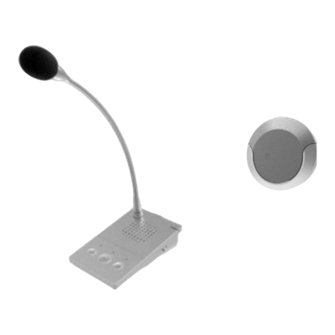
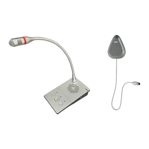
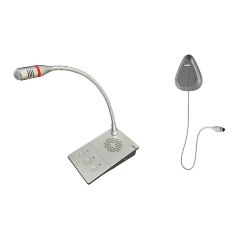
Opus Technologies OP-6505H User manual

Installation and user manual
OP-6505H OP-6510
Window intercom

1
1 Presentation . . . . . . . . . . . . . . . . . . . . . . . . . . . . . . . . . . . . . . . . . . . . . . . . . . . . . . . .1
1.1 Introduction . . . . . . . . . . . . . . . . . . . . . . . . . . . . . . . . . . . . . . . . . . . . . . . . . . 1
1.2 Technical caracteristics . . . . . . . . . . . . . . . . . . . . . . . . . . . . . . . . . . . . . . . . . .2
1.3 Package content . . . . . . . . . . . . . . . . . . . . . . . . . . . . . . . . . . . . . . . . . . . . . . . .2
1.4 OP-6505HB and OP-6510B . . . . . . . . . . . . . . . . . . . . . . . . . . . . . . . . . . . . . . .3
1.5 Description . . . . . . . . . . . . . . . . . . . . . . . . . . . . . . . . . . . . . . . . . . . . . . . . . . . .3
1.5.1 Microphone/speaker client side . . . . . . . . . . . . . . . . . . . . . . . . . . . . . .3
1.5.2 Central unit agent scheme . . . . . . . . . . . . . . . . . . . . . . . . . . . . . . . . . . .3
1.5.3 Connection wiring . . . . . . . . . . . . . . . . . . . . . . . . . . . . . . . . . . . . . . . . .4
1.6 Safety 5
1.6.1 Safety indications . . . . . . . . . . . . . . . . . . . . . . . . . . . . . . . . . . . . . . . . . .5
1.6.2 Safety instructions . . . . . . . . . . . . . . . . . . . . . . . . . . . . . . . . . . . . . . . . .6
2 Installation . . . . . . . . . . . . . . . . . . . . . . . . . . . . . . . . . . . . . . . . . . . . . . . . . . . . . . . . .7
2.1 Principle scheme . . . . . . . . . . . . . . . . . . . . . . . . . . . . . . . . . . . . . . . . . . . . . . . 7
2.2 Loop installation . . . . . . . . . . . . . . . . . . . . . . . . . . . . . . . . . . . . . . . . . . . . . . . 7
2.2.1 Presentation of DCL20-65 kit . . . . . . . . . . . . . . . . . . . . . . . . . . . . . . . .7
2.2.2 Loop connection . . . . . . . . . . . . . . . . . . . . . . . . . . . . . . . . . . . . . . . . . . .8
2.2.3 Loop installation in the reception desk . . . . . . . . . . . . . . . . . . . . . . . . .9
3 Use . . . . . . . . . . . . . . . . . . . . . . . . . . . . . . . . . . . . . . . . . . . . . . . . . . . . . . . . . . . . . . 11
3.1 Local intercom duplex conversation . . . . . . . . . . . . . . . . . . . . . . . . . . . . . . 11
3.2 Recording . . . . . . . . . . . . . . . . . . . . . . . . . . . . . . . . . . . . . . . . . . . . . . . . . . . 11
3.3 Volume level adjustement . . . . . . . . . . . . . . . . . . . . . . . . . . . . . . . . . . . . . . 11
3.3.1 Adjust volum level in duplex . . . . . . . . . . . . . . . . . . . . . . . . . . . . . . . 11
3.3.2 Adjust volume level separately . . . . . . . . . . . . . . . . . . . . . . . . . . . . . 11
4 Warranty certificate . . . . . . . . . . . . . . . . . . . . . . . . . . . . . . . . . . . . . . . . . . . . . . . . .12

1
Presentation
1 Presentation
1.1 Introduction
This guide has objective to introduce you to the installation and utilisation of window intercom systems OP-505H
and OP-6510 provided by Opus Technologies. These system are designed to be relevant for many purpose :
• Ticket and service counters.
• Retail counters.
• Money exchange.
• Information kiosks.
• Reception desks.
• Interview rooms.
OP-6505H and OP-6510 window intercom systems provide following features :
• Possibility to connect a magnetic loop system for hearing aided people.
• DSP multi-channel language auto-control technology that permits to realize real digital full-duplex intercom
avoiding squeaking and disturbance.
• Full touchable transparent key design (only OP-6505H) to keep intercom free fromdisturbing key-clicks and
easy to keep clean by just swiping it.
• Sound source recognizing, environment noise control, automatic or manual volume adjustement and original
sound restoration.
• Three scene mode (quiet, standard, noisy), one-key adjustement support.
• Professional enclosure structure design adopting alluminum enclosure to prevent machine resonance and
ensure long term product durability.
• Audio output to connect third-party recording storage such as DVR systems.
• LED showing if device is on communication.
• Mic headset fonction to allow agents to isolate themselves of background noise (only available on OP-6505H).
• Rainproof and IP-65 compliant client microphone/speaker.
OP-6505H OP-6510

2
Presentation
1.2 Technical caracteristics
1.3 Package content
Following elements are included :
• central unit agent + microphone (X1 set)
• Gooseneck microphone (X1)
• Power adapter 12V (X1)
• Wiring clips 3 x 100 mm (X3)
• Cable clamp HC-100 (X3)
• Wiring connector 3.81-2P (X1)
• Quick installation manual (X1)
• Headset (only with the OP-6505HK)

3
Presentation
1.4 OP-6505HB and OP-6510B
You bought a window intercom system with a DLC20-65 kit. It allows you to install a magnetic loop system.
To have more informations about the installation of magnetic loop in the reception desk, see “Loop installation”,
page 7.
1.5 Description
1.5.1 Microphone/speaker client side
1) Speaker / Microphone : Contents the speaker to
amplify the local audio intercom and the microphone
to receive agent speaking.
2) 6-pin connector to central unit agent.
1.5.2 Central unit agent scheme
Front view of OP-6505H :
1) Red light : Device working indication
2) Loudspeaker : Audio from client microphone amplifier.
3) Recording key : Allows to make a recording of the current
conversation.
4) Central key : Allows to begin a call with the client.
5) 3-pin microphone pole socket : Plug for microphone pole.
6) Phone key : Permits to diffuse automatic "Hello"/"Goodbye"
messages by pressing it.
OP-6505H microphone/speaker client
OP-6510 microphone/speaker clientz

4
Presentation
Front view of OP-65010 :
1) Red light : Device working indication
2) 3-pin microphone pole socket : Plug for microphone pole.
3) Loudspeaker : Audio from client microphone amplifier.
4) Recording key : Allows to make a recording of the current
conversation.
5) Central key : Allows to begin a call with the client.
6) Phone key : Permits to diffuse automatic "Hello"/"Goodbye"
messages by pressing it.
Central unit agent side view :
1) Scene mode ajustement switch :
• Mode 1 : Noisy environnement.
• Mode 2 : Normal environnement.
• Mode 3 : Quiet environnement.
2) Headset jack 3.5 mm socket : Only available on OP-6505H.
1.5.3 Connection wiring
1) Power supply : Connect to a 12VA/2A plug.
2) IP Network : Allows to connect a POE switch for intercom interconnections.
3) Analog audio output interface : Connect to a DVR, a loop amplifier or an IP
camera.
4) External audio plug : Connect to client microphone/speaker.

5
Presentation
1.6 Safety
1.6.1 Safety indications
The icons used in combination with Caution and Warning indicate the type of risk. See the following examples:
• This symbol is used to alert the user to important operating or maintenance instruction.
• This lightening bolt triangle is used to alert the user to the risk of electric shock.
• This symbol alert the user to important risk of electrostatic discharge.
• This symbol alert the user to important risk of burn if customer is touching the device while
operating.

6
Presentation
1.6.2 Safety instructions
Safety :
• Do not scratch, cut or twist the power cord.
• If the device is under maintenance or is unused for 10 days or more, shut down the device and
pull out the plug.
• Do not put any heavy, or metallic object on the device.
• Do not open or modify the device internal. Please contact your supplier.
• In case product fall into the floor, do no use the device until it has been checked by an
authorized dealer.
Burn risks :
• Do not put metal or inflammable objects in the device internal or around the device.
• In case of smoke or suspicious odour, switch off and unplug the device then contact your
supplier.
Electroshock risks :
• Do not place the device under water or in any liquid stained environnement to prevent the risk
of electroshock.
• Do not place any object containing liquid around the device.
• In case of any anomaly appearing, please shut off the power supply immediately and contact
your supplier.
• Do not use another power voltage than the one indicated to connect the device.
• Do not touch the device and the plug in case of lightning.
• Keep the power supply away from the working device.
Please respect these indications for your safety and to maintain the proper functioning of the device. Every
maintenance operation must be operated by professionnal personnel.

7
Installation
2 Installation
2.1 Principle scheme
Connect your system according to the scheme above.
Notes :
• DVR connection possible with 2 male connector audio output.
• DVR system must have a button.
• A RJ45 Ethernet socket is only available on OP-6505H.
2.2 Loop installation
2.2.1 Presentation of DCL20-65 kit
The DCL20-65 is a part of Opus Technologie serie of induction loop amplifier. It covers rooms from 50m² to
2000m².
Kit contents :
• DCL20-65 amplifier with integrated connectors (X1)
• Power supply (X1)
• A 1,80m loop cable and adaptor (X1)
• Link cable (X1)
• Audio cable (X1)
• Adhesive clips
• Stickers "space adapted for hearing impaired" (X3)

8
Installation
2.2.2 Loop connection
A magnetic induction loop is composed of 3 elements :
• A loop cable
• A loop adapter
• A connecting cable
The loop is delivered "ready to use" but it is possible to disassemble it to adapt it to the reception desk shape.
Follow the steps to operate it :
• Unscrew the support of the electronic card as shown on figure 1.
• Connect the beginning and the end of the loop cable to the circuit board (red
connector).
• Plug the 50-70 cm connecting cable to the "Amplifier" connector of the adaptator and
to the "Loop" terminal block to the amplifier as shown on figure 2.
Figure 1
Figure 2

9
Installation
2.2.3 Loop installation in the reception desk
There are different ways to install the magnetic loop with the central unit agent. We recommend the first
installation described below.
1) Loop installation inside the reception desk :
• Place the loop on vertical and horizontal portion as
shown in the figure 3, astride the corner of the
reception desk.
This solution is recommended because it ensure better
coverage in front of the reception desk.
2) Double loop installation inside the reception desk :
• Place one loop horizontally on the top of the
reception desk and another one vertically on the
countertop, as shown in the figure 4 opposite. Both
has to be as close as possible from the client.
• Fix the loop using the binding clips supplied. For
better durability, it is possible to install the loop in
a plastic chute.
• Connect the link cable to the "Amplifier" terminal
block of the amplifier.
• Connect the loop to the "Loop" terminal block of
the amplifier.
• Screw the connector at the drawn cross level.
Do not position the loop under a metal structure. The magnetic field would be absorbed by the
metal mass and would leading to unproper audio coverage. See the next solution to install a loop on
a metallic reception desk.
Figure 3
Figure 4

10
Installation
3) Loop installation in the floor (for metallic reception
desk) :
• According to your environnement situation, place
the loop in the slab (over the wire mesh) or under a
coating (parquet, carpet, etc.) using a copper tape
or glued under a carpet as shown on figure 5.
The wire supplied in the DCL20-65 kit produces a
magnetic field radiating on a perimeter of 1.2 m which
allows a people to receive the signal comfortably.
To avoid disturbance due to metal, the "Hearing
impaired" pictogramme can be fixed on the reception
desk turned to the client side, as shown on figure 6.
Figure 5
Figure 6

11
Use
3 Use
3.1 Local intercom duplex conversation
• Push the main button of the central unit agent to begin a duplex conversation. The red
LED around the central unit agent microphone light on to confirm the system is
working properly.
• When conversation is done, push the main button of the central unit agent again to
end the duplex and desactivate the system.
3.2 Recording
The central unit agent can be connected to a DVR by an output analog audio (see “Principle scheme”,
page 7). The recording is automatically recorded on the hard disk of the DVR. See your DVR product
guide to get more informations.central unit agent
3.3 Volume level adjustement
3.3.1 Adjust volum level in duplex
On the left side of the central unit agent, select a mode with the swith depending your current environnement :
•Mode 1 : Noisy environnement.
•Mode 2 : Normal environnement.
•Mode 3 : Quiet environnement.
3.3.2 Adjust volume level separately
Press simultaneously phone key and voice broadcast button during 4 seconds to activate the separate level
volume adjustement function :
• Press shortly the recording key to increase the volume of the client speaker.
• Press shortly the phone key to increase the volume of the central unit agent speaker.
• Press longer (2sec) the recording key to decrease the volume of the client speaker.
• Press longer (2 sec) the phone key to decrease the volume of the central unit agent speaker.
• Press and hold the recording key to continuously decrease the volume of the client speaker.
• Press and hold the phone key to continuously decrease the volume of the central unit agent speaker.
Press again simultaneously phone key and voice broadcast button during 4 seconds to desactivate the separate
level volume adjustement function.
The volume setting ranges from 1 (low) to 15 (high).

4 Warranty certificate
Our window intercom devices complies with following CE directives :
• EN-5503:2015
• EN-55035:2017
• EN-61000-3-2:2014
• EN-61000-3-3
• ROHS directive

Pour consulter la liste de nos partenaires de services, contactez-nous ou
rendez-vous sur notre site internet :
To see our service partners, please contact us or visit our website :
Opus Technologies
4 Allée Pierre-Gilles de Gennes
Technopôle Montesquieu
3650 MARTILLAC
Tel : (+33) 06 58 29 53 15
Mail : [email protected]
This manual suits for next models
1
Table of contents
Other Opus Technologies Intercom System manuals