Orno OR-VID-CK-1039 Quick start guide

Video
Door Entry System
Kits
4 Wires Installation
Safety & Operating Instructions
OR-VID-CK-1039

Page
1
These instructions are for your safety. Please read through them
thoroughly before use and retain for future reference.
Before You Start
Check the pack and make sure you have all of the part listed above. If not,
contact your local store who will be able to help you.
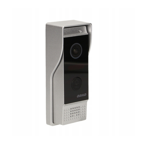
This video door phone is composed of a monitor with its power transformer and a
outdoor camera.It allows communicating with the visitor who calls at the door and
controlling the opening of the door and/or gate.You can develop your installation
by adding an optional additional monitor and/or a second roadside panel.For a
safe installation and use, please read carefully these instructions and keep them
safe.
Parts Supplied
Fittings Supplied
Ref
Description
Illustration
Qty
Ref
Description
Illustration
Qty
A
Indoor
Monitor
1
F
Power cover
1
G
Locker
2
H
Bracket
Holder
1
B
Outdoor
Camera
1
I
Screw B1
2
Screw B2
1
Screw B3
1
Scew B4
1
C
Wall
mounting
bracket
1
J
Wall plug
6
D
Power
Supply
1
K
Accessory
Connector
2
E
Screws A
4

Page
2
Technical Characteristics
Indoor Unit (NVM-904)
Specifications
Dimensions
200[W] x145 [H] x23 [D] mm
Weight
0.5Kg
Input Power
DC15V (External Power Supply)
Power Consumption
Idle mode : 2W Operating : Max 14W
Connecting System
4 wires; 2 Cameras, 2 Monitors
Voice transmission
Halfduplex twowaycommunication
Call sound
Chime sound
Max. Distance & wiring
Monitor to Camera
50M : 0.65mm2wire
100M : 1.0mm2wire
Master to Slave 20M: 1.0mm2 wire
Door Lock to Camera 20M : 1.0mm2wire
Video S/N Ratio
50dB
Audio S/N Ratio
40dB
Aspect Material
Acryl
Display
7 Inch Digital Wide Screen LCD(LED Backlight)
Resolution
1440(H)X234(V)
Monitor on time
Stanby:30sec Autooff:60sec
Users Control
Ringsoundvolume;Receivesoundvolume
Operating Temperature
0~40℃
Storage Temperature
-20~60℃
Outdoor Unit (NVC-6104)
Specifications
Dimensions
39[W] x129[H] x 23 [D] mm
Weight
0.3Kg(W/rain shield)
Input Power
DC12V from monitor
Power Consumption
Max 3W
Aspect Material
Zinc Alloy Die Casting
Wiring
Monitor to Camera:4wires Door lock:2Wires
Image sensor
1/4" Colour CMOS Camera
TV system
PAL
Resolution
700 TV Lines
Video output
Composite video signal 1Vp-p at 75 ohm
terminated
No. of pixels
290,000.pixels
Iris
Electronic auto iris
Lighting
940nm Invisible IR LED
Viewing Angle
Diagonal:70˚ horizontal:51˚ vertical:41˚
Lens
3.7mm super cone pin hole lens
Min. Illumination
0.5Lux
Door lock open
2 terminals from outdoor station with DC power
output max 12V 500mA
Gate open
2 terminals from indoor monitor with dry contact
Mounting type
Surface mount with rainshield and angle bracket
Operating Temperature
-1 0˚C ~ 50˚C(14°F ~ 122°F)
Storage Temperature
-20˚C ~ 60˚C

Page
3
Indoor unit
1. Monitor screen
2. Talk on/Talk off (Monitor off)
3. Door lock Open
4. Camera 1 / Camera 2
5. Intercom
6. Gate Open
7. Microphone
8. Menu Select(Brightness,Contrast,Color)
9. Down
10.Up
11.Ring Sound volume
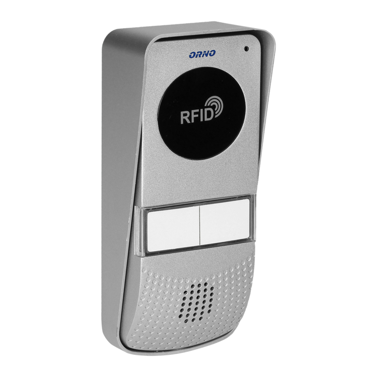
Outdoor unit
1. Microphone
2. Camera
3. IR LEDs for night vision
4. Call button
5. Speaker

Page
4
Safety Instructions
1. Do not install near other electronic equipment such as computers, TV, video
recorder as this may cause radiated interference to the unit.
2. Do not disassemble the unit.
3. Do not spray water on the indoor unit. Do not keep the outdoor unit where it will
be exposed to extreme moisture.
4. Do not overload mains wall outlets or extension cords.
5. Do not drop or shock the unit.
6. Remove the power cord from the wall socket when unit is not used for long periods.
7. Do not place any naked flames (e.g. lighted candles) on the apparatus.
8. Do not place objects filled with water (e.g. vases) on the apparatus.
9. Do not cover the ventilation holes with clothing, paper, curtains etc.
10. This apparatus is designed for moderate climates. Do not use in high humidity,
dusty or dirty areas.
11. To disconnect or isolate the unit, switch off at the socket or remove plug from wall
socket. Please ensure the plug and socket is easily accessible.
Warnings
1. Do not install the outdoor unit where it will be exposed to direct sunlight or any
strong reflected light. Avoid extremely bright locations for the indoor unit as the
monitor screen image will be adversely affected.
2. Do not install the outdoor unit where it will be subjected to extremes of dust or
moisture.
3. Do not install the outdoor unit where it will be exposed to rain.
4. Do not install near acid oxides, ammonia, or any harmful gas (it might cause
malfunction).
5. Do not install the outdoor unit in a location where the lens filter is likely to get
scratched or very dusty.
6. Check cables are connected correctly and camera unit is firmly installed.
Assembly instructions

Page
5
WIRING DIAGRAM
ONE-FAMILY SYSTEM WITH ONE MONITOR AND ONE CAMERA

Page
6
WIRING DIAGRAM
ONE-FAMILY SYSTEM WITH TWO MONITORS AND TWO CAMERAS

Page
7
A) Cable connection
1. Connect the monitor to the camera with the cable according to the wiring
diagram.
2. Carefully insert the wires to the terminal by pressing down the terminal flap with
any small tool taking care that the 2 bare wires do not touch.
B) Installation height
1. Recommended installation height is approximately 140cm for monitor unit and
150cm for outdoor camera.
C) Installation of indoor monitor
1. Fix the wall mounting bracket in the best place by using 4 screws and plugs.

Page
8
2. Carefully place the indoor monitor against the bracket and gently push down the
monitor so that the pins on the bracket engage in the slots on the rear of the
monitor.
3. Secure the assembly with the 2 screws.
Only after having connected the roadside panel,connect the 230 V~ power supply
to the adapter.
Make sure the power supply polarity is correct.
D) Installation of outdoor camera (Two ways for option)
Options
Screws to be used
Adding the Angel Bracket
Screw B1 Screw B2 Screw B3
Without Angel Bracket
Screw B1 Screw B4
Option 1 (With angle bracket)
1) Screw the angle bracket to the wall by 2 screws (Screw B1) (Fig.1)
2) Screw the rainshield to the angle bracket by the screw B2 (Fig. 2)
3) Connect all the wires & install the door panel inside the rainshield (Fig. 3)
4) Fix the door panel inside the rainshield by the screw (Screw B3) (Fig. 4)
5) Install the cap and fix it tightly (Fig. 5&Fig. 6)
1 2 3

Page
9
4 5 6 6
Option 2 (Without angle bracket)
1) Screw the raishield to the wall by 1 screw (Screw B1) (Fig.1)
2) Connect all the wires & install the door panel inside the rainshield (Fig. 2)
3) Fix the door panel inside the rainshield by the screw (Screw B4) (Fig. 3)
4) Install the cap and fix it tightly (Fig. 4&Fig. 5)
1 2 3
4 5 5
Important:Do not point the video camera directly at the sun or at reflecting surfaces.

Page
10
E) Installation of the transformer
Attach the transformer to a DIN rail in a modular fusebox or to a flat surface using
the two black lugs clipped to the sides of the power supply.
Performance Settings
You can adjust the brightness,contrast and colour of the monitor when it is ON by
pressing the Menu button at the side of the monitor.
Press the Menu button then the brightness,contract and colour indication will appear.
To select the indication by pressing the Up and Down buttons,then press the Menu
button to confirm the selection and then press the Up and Down buttons to adjust.
Finally,press the Menu button to confirm the setting.
Operating Instructions
Important:The touch keys must be handled by slightly touching with the fingers.
1. Activation of units
When the call button on the outside camera unit is pressed, the indoor unit chime
rings and the visitor’s picture will appear on the indoor monitor. After the visitor is
visually identified,and if you wish to talk with the visitor,touch the button.The
unit will remain activated for approximately 60 seconds before it automatically
shuts off.
To re-activate for continued conversation,touch the button and then touch the
button.
2. Activation of outside unit from monitor unit
a) Touch the button of the indoor unit at any time and the outdoor camera
will be activated and show the outside view.
b) If you has installed two cameras,touch this button to change from camera
one to another.
If you press twice the button that the camera is not connected,you have a
black screen and a noisy sound.After 1 second,the video of the main camera
reappears.
3. Working time
a) Call time: Approximately 30 seconds
The picture terminates automatically if indoor unit is not answered within
approximately 30 seconds after the call button of the outdoor camera unit is
touched.
b) Talk time: Approximately 60 seconds
When monitor unit is called by the outdoor unit and the monitor is answered,
there is approximately 60 seconds of time available before the unit
automatically shuts off.

Page
11
c) Monitor time: Approximately 30 seconds
When outside camera is activated from the inside,there is approximately 30
seconds of viewing time before the unit automatically shuts off.
4. Activation of “Intercom” button
An intercom calling can be started by any indoor monitor.
When the intercom button on one indoor monitor is touched, this will ring all
monitors in a system,you can talk with the one calling monitor by touching the
intercom button on the second monitor,touch for shutting off.There is
approximately 60 seconds of time before the unit automatically shuts off.
5. Activation of button
If an electrical lock or door strike is added to the installation,connect it to the
terminals at the back of the roadside panel.
If you want to open the door to let the caller in,just touch the button on the
indoor monitor.
This function can only be used when the screen is switched on.
Important:It is essential that the electric latch or lock installed has a mechanical
memory.
6. Activation of button
Connect the automatic gate opener directly to the terminals at the back of the
indoor monitor which supplies a current-free “dry” contact to connect to the “push
button” control of your automatic gate opener.
If you want to open the gate to let the caller in,just touch the button on the
indoor monitor any time when the power is on.
7. Change the melody
At standby mode,touch the button,you can hear the melody.Then touch
to choose target melody.There are 4 melodies available.To confirm melody you
have chosen,touch button.

Page
12
Care and Maintenance
Do not store in hot or cold areas. Extreme hot or cold temperatures can shorten
the life of electronic devices and can distort/melt certain plastics or may cause
malfunction.
Dropping can result in failure to operate. Circuit boards can crack and may not
survive the impact.
Do not use or store in areas of high levels of dirt or dust. The electronics may be
contaminated. Any moving parts will wear prematurely.
Do not use harsh chemicals, cleaning solvents or strong detergents. To clean,
wipe with a damp cloth from time to time.
Troubleshooting
No
Problem
Check point
1
No power
(no picture on monitor)
Is the AC plug firmly inserted into
the AC outlet?
2
Power is on, but no
picture on the monitor
Is the cable firmly connected
between the monitor and the
camera?
Is the polarity of wires correct
between the outdoor camera unit
and indoor monitor unit?
3
The picture is too dark
or white
Adjust brightness control
4
Chime sound is too low
Adjust the volume control
Environmental Protection
Waste electrical products should not be disposed of with household
waste. Please recycle where facilities exist. Check with your Local
Authority or retailer for recycling advice.
Table of contents
Other Orno Intercom System manuals

Orno
Orno OR-DOM-CL-909 User manual

Orno
Orno OR-VID-JS-1053/W Specification sheet

Orno
Orno ERATO AC OR-DB-AX-151 User manual

Orno
Orno OR-DOM-RE-914 User manual

Orno
Orno OR-VID-IP-1045 User manual

Orno
Orno OR-DOM-AT-930/W User manual

Orno
Orno OR-DOM-RL-913 User manual

Orno
Orno SECURIT OR-IK-LY-931 User manual