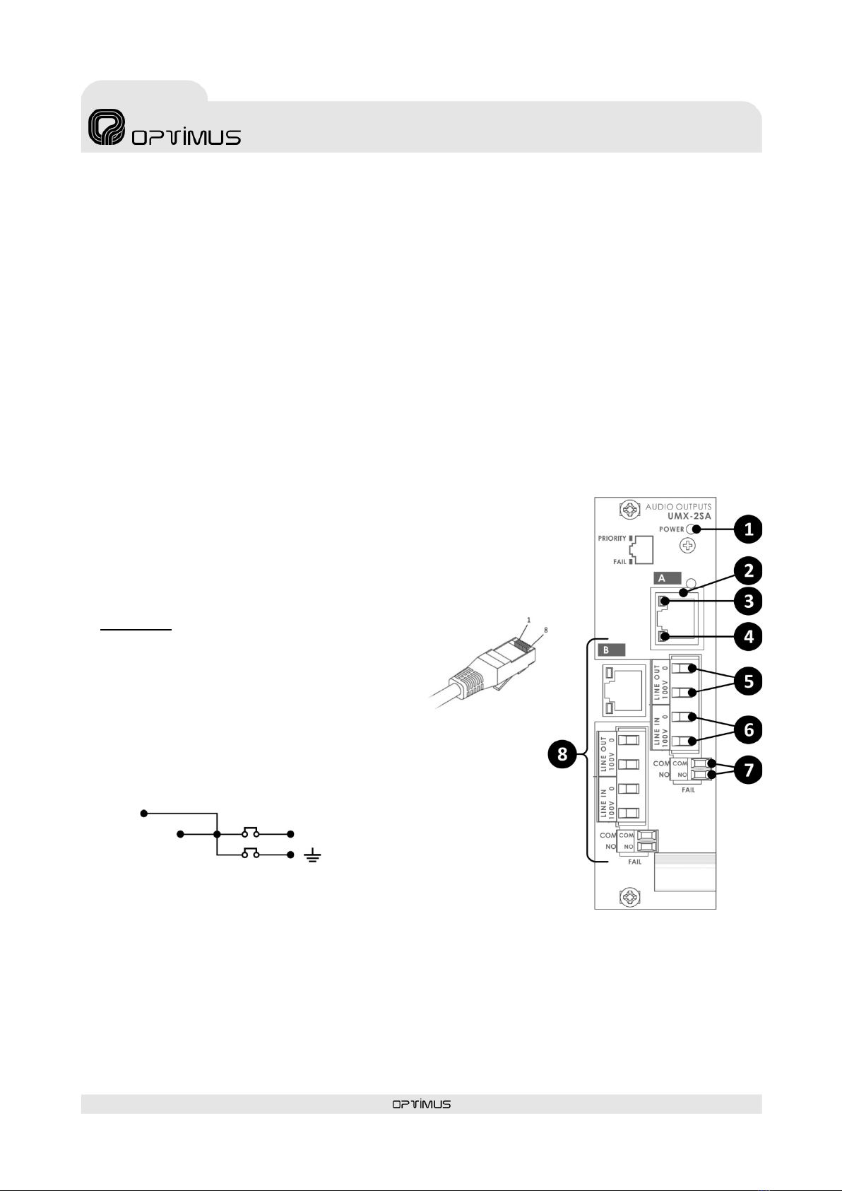
Card with two audio outputs
with surveillance functions
UMX-2SA
9. GUARANTEE
1. GUARANTEE CERTIFICATE
1. OPTIMUS S.A. guarantees that its products are free from material and
manufacturing defects when they are first delivered to the purchaser.
2. In accordance with the conditions outlined here, OPTIMUS S.A. guarantees
its products for two (2) years from the date on which the purchaser acquires the
product. If, within this guarantee period, defects appear which are not due to
factors outlined in section 2, OPTIMUS S.A. shall replace or repair the unit using
equivalent, new or reconstructed replacement parts, as it deems fit. If
replacement parts are applied which improve the unit, OPTIMUS S.A. reserves
the right to charge the client for the additional cost of these components.
3. No guarantee benefits shall be provided other than those cited here.
4. In order to claim the guarantee rights, it shall be an essential requirement
to present the original purchase invoice or the guarantee certificate.
2. GUARANTEE PROVISIONS
1. In the event that the product had to be modified or adapted to comply with
local requirements concerning technical specifications or safety, and if the
country in question is not the country for which the product was originally
designed and manufactured, defects are not considered to be material or
manufacturing defects. Furthermore, the guarantee does not cover the
execution of these modifications or adaptations, regardless of whether or not
they have been carried out correctly.
Nor shall OPTIMUS S.A. be responsible for any costs under this guarantee for
these types of modifications.
2. The guarantee shall not entitle the purchaser to inspection or free
maintenance or repair of the unit, particularly if the defects are due to
inappropriate use. Nor do the guarantee rights cover defects in wearing parts
that become worn as a result of normal wear and tear. Wearing parts are, in
particular, potentiometers, switches/keys, and similar parts.
3. The guarantee does not cover defects in the equipment unit caused by:
•Abuse or incorrect use of the unit for purposes other than those for which it
is intended, in non-compliance with the service and maintenance
instructions specified in the Manual and/or Technical Instructions for the
unit.
•Connection or use of the product in a manner that does not correspond to
the technical or safety requirements of the country in which the unit is
used.
•Installation in conditions other than those indicated in the Manual and/or
Technical Instructions.
•Deficiency or interruptions in the electricity supply or installation defects
which imply use in abnormal conditions.
•Damage caused by other equipment units that are connected to the
product.
•The use or installation of Software (programmes), interfaces, parts or
supplies not provided and/or not authorised by OPTIMUS S.A.
•Failure to use the original packaging for transportation.
•Damage caused by force majeure or other causes not attributable to
OPTIMUS S.A.
4. The following elements are not covered by this guarantee:
•All plastic surfaces and all parts exposed to outdoor conditions which have
been scratched or damaged as a result of normal or abnormal use.
•Breakages, knocks, damage due to a fall or scratches caused by moving the
unit in any way.
•Damage caused by tests, use, maintenance, installation or inappropriate
adjustments, or as a result of any alteration or modification of any kind not
carried out by a Service Authorised by OPTIMUS S.A. in compliance with this
guarantee.
•Damage to persons or property that might be caused by the improper use
of the equipment, including lack of maintenance.
5. The guarantee shall not be valid whenever the following is observed:
•Amendments or corrections made to the details of the guarantee certificate
or purchase invoice.
•Failure to produce the original invoice or the absence of a date on this.
•Absence of the serial or batch number on the equipment.
6. In the case of personal computers, the guarantee will not cover the
elimination of computer viruses, the restoration of programmes damaged by
these or the reinstallation of the disk following its deletion.
7. The rights of this guarantee are invalidated if the product has been repaired
or opened by staff unauthorised by OPTIMUS S.A. or by the client himself.
8. If OPTIMUS S.A. were to establish before the client that the damage
affecting the unit does not entitle a claim to be made under the guarantee, the
costs of checking the equipment incurred by OPTIMUS S.A. shall be borne by the
client.
9. Products not covered by the guarantee shall only be repaired once payment
has been effected by the client. In the event that the guarantee rights do not
apply, OPTIMUS S.A. shall duly inform the client. If, within a period of 6 weeks
from this communication, no written repair order is received from the client
confirming acceptance of the costs, OPTIMUS S.A. shall return the unit in
question to the client. In this case, the transport and packaging costs shall be
invoiced separately and payment shall be made on delivery. In the event that a
repair order is sent by the client, confirming that he assumes the costs of repair,
the transport and packaging costs shall be invoiced additionally, and also
separately.
10. If the equipment needs to be transferred to the Authorised Service Centre,
transportation shall be effected by the responsible party according to the
guarantee, who will also bear the freight and insurance costs.
11. In the event of a defect, OPTIMUS S.A. guarantees that the repair and/or
replacement of parts so that the unit operates correctly will be made within a
period of no more than 30 days. Nevertheless, OPTIMUS S.A. would like to clarify
that the normal period does not exceed 30 days.
12. All parts or products replaced as part of the guarantee services shall
become the property of OPTIMUS S.A.
3. TRANSFER OF GUARANTEE
The guarantee is solely awarded to the original purchaser (principal client) and is
not transferable. With the exception of OPTIMUS S.A., no third party (dealers,
etc.) is authorised to award additional guarantees on behalf of OPTIMUS S.A.
4. CLAIMS FOR DAMAGE
In the event that OPTIMUS S.A. cannot provide a suitable guarantee service, the
purchaser shall not be entitled to claim any indemnity for damages arising. The
responsibility held by OPTIMUS S.A. is limited in all cases to the invoicing price of
the product.
5. RELATION WITH OTHER GUARANTEE RIGHTS AND NATIONAL LAW
1. This guarantee does not affect the rights of the purchaser with respect to the
vendor arising from the contract of sale accomplished.
2. These conditions of the guarantee provided by OPTIMUS S.A. are valid as long
as they do not contradict the corresponding national law on guarantee
provisions.
3. OPTIMUS S.A. guarantees that this product complies with the safety
regulations in force in the country.
THIS LIMITED GUARANTEE DECLARATION IS THE EXCLUSIVE GUARANTEE
OFFERED BY OPTIMUS S.A. ALL OTHER EXPLICIT OR IMPLICIT GUARANTEES ARE
EXCLUDED, AND THIS ALSO APPLIES TO GUARANTEES OF MARKETABILITY AND
SUITABILITY FOR A PARTICULAR PURPOSE. (EXCEPT WHEN THESE GUARANTEES
ARE REQUIRED BY AN APPLICABLE LAW). NO GUARANTEE, EITHER EXPLICIT OR
IMPLICIT, SHALL BE APPLIED ONCE THE GUARANTEE PERIOD HAS EXPIRED
OPTIMUS S.A.
Servicio Post Venta
C/ Barcelona 101
17003 - GIRONA
Tel. 902 151 96 / 972 203 300
Fax. 972 21 84 13
e-mail:girona@optimus.es 1999/44/CE