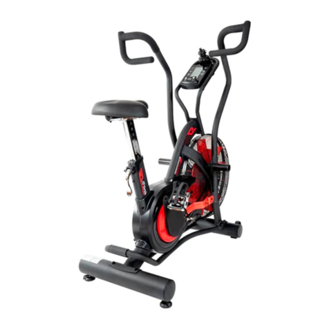
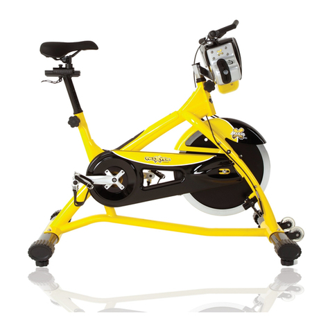
Orbit Fitness OBK2060 User manual

1
TABLE OF CONTENTS:
IMPORTANT SAFETY NOTICE.......................................................2
HARDWARE IDENTIFICATION CHART .........................................3
ASSEMBLY INSTRUCTION ......................................................4/5/6
EXPLODED DIAGRAM ..................................................................7
PARTS LIST ................................................................................8/9
EXERCISE COMPUTER ..............................................................10

2
IMPORTANT SAFETY NOTICE:
PRECAUTIONS
This exercise machine is built for optimum safety. However, certain precautions apply
whenever you operate a piece of exercise equipment. Be sure to read the entire manual
before you assemble or operate your machine. In particular, note the following safety
precautions:
1. Keep children and pets away from the machine at all times. Do not leave
children unattended in the same room with the machine.
2. Only one person at a time should use the machine.
3. If the user experiences dizziness, nausea, chest pain, or any other abnormal
symptoms, Stop the workout at once. CONSULT A PHYSICIAN IMMEDIATELY.
4. Position the machine on a clear, leveled surface. DO not use the machine near water
or outdoors.
5. Keep hands away from all moving parts.
6. Always wear appropriate workout clothing when exercising. Do not wear robes or
other clothing that could become caught in the machine. Running or aerobic shoes
are also required when using the machine.
7. Use the machine only for its intended use as described in this manual. Do not use
attachments not recommended by the manufacturer.
8. Do not place any sharp object around the machine.
9. Disabled person should not use the machine without a qualified person or physician in
attendance.
10. Before using the machine to exercise, always do stretching exercises to properly
warm up.
11. Never operate the machine if the machine is not functioning properly.
12. The Maximum Weight Capacity is 100kg.
13. Read all warning stickers posted on the exercise bike.
14. Inspect the exercise bike for worn or loose component prior to use. Tighten/replace
any loose or wore components prior to use.
15. Care should be taken in mounting or dismounting the exercise bike.
16. This exercise bike is only for consumer use only.
WARNING: BEFORE BEGINNING ANY EXERCISE PROGRAM, CONSULT
YOURPHYSICIAN. THIS IS ESPECIALLY IMPORTANT FOR INDIVIDUALS OVER THE
AGE OF 35 OR PERSONS WITH PRE-EXISTING HEALTH PROBLEMS. READ ALL
INSTRUCTIONS BEFORE USING ANY FITNESS EQUIPMENT.

3
HARDWARE IDENTIFICATION CHART:
This chart is provided to help identify the hardware used in the assembly process. Place the
washers or the ends of the bolts or screws on the circles to check for the correct diameter.
Use the small scale to check the length of the bolts and screws.
MILLIMETERS
After unpacking the unit, open the hardware bag and make sure that you have all the
following items. Some hardware may be already attached to the part.
THE FOLLOWING TOOLS ARE INCLUDED FOR ASSEMBLY:
Wrench(13mm-15mm) Allen Wrench (5mm) Allen Wrench (5mm) Cross wrench
Part
No.
Description
Quantity
30
Carriage Bolt (M8 x 1.25 x 45mm)
4
40
Bolt, Button Head (M8 x 1.25 x 20mm)
4
65
Bolt, Button Head (M8 x 1.25 x 45mm)
4
50
Flat Washer (M4)
4
59
Flat Washer (M8)
9
16
Spring Washer (M8)
3
66
Arc Washer (M8)
12
67
Acorn Nut (M8 x 1.25)
8
48
Nylock Nut (M8x1.25)
6
44
Screw, Round Head (M4 x 15mm)
4
mm.
INCHES
in

4
ASSEMBLY INSTRUCTION:
1. PREPARATION:
A. Before assembling make sure that you will have enough space around the item.
B. Use the present tooling for assembling.
2. ASSEMBLY INSTRUCTIONS:
STEP 1
Diagram 1
A) Attach the Front Stabilizer (3) to the
Main Frame (1). Secure it with two
M8x 45 Carriage bolt (30), Washers
(59),Acorn Nut (67).
B) Attach the Rear Stabilizer (2) to the
Main Frame (1). Secure it with two
M8x 45 Carriage bolt (30), Washers
(59),Acorn Nut (67).
STEP 2
Diagram 2
A) Connect the Connection Wire (75) to
the Sensor Wire (70). Insert the
Exercise computer Post (5) onto the
Main Frame (1) and secure with Button
Head Bolts (M8x1.25x20mm) (40), Arc
Washers (M8) (66).
B) Install two AA batteries into the
Exercise computer (26). Plug the
Connection Wire (75)into the Exercise
computer (26). Slide the Exercise
computer (26)onto the plate on the
Exercise computer Post (5) and Secure
it with four M4x15mm Screw, Round
Head (44), Washers (50).
C) Install the Water Bottle Holder (80) onto
the Exercise computer Post (5) and
secure with two M5x10mm Screw,
Round Head (31).
2
3
1
30
30
59
59
67
67
59
59
30
30
80
31
50
44
50 44
75
26
5
66
66
40
40
75 70
1

5
STEP 3
Diagram 3
A) Insert the Left and Right Handlebars
(6/7) onto the Handlebars Posts on
the Main Frame (1). Slide Pedals (8)
onto the Handlebars (6/7) and
Secure it with four Button Head Bolts
(M8 x 45mm)(65), Arc Washer (66),
Acorn Nut (67).
STEP 4
NOTE: The Right Pedal (39) has R stamped on the end of the pedal shaft. The Right
Pedal R (39) has right hand threads and is tightened by turning clockwise.
The Left Pedal (11) has L stamped on the end of the pedal shaft. The Left
Pedal (11) has left hand threads and is tightened by turning counterclockwise.
Diagram 4
A) Install the Right Pedal (39)into the
Right Crank(58)as shown. Tighten the
pedal securely. Repeat on the left side
to attach the Left Pedal (11)to the Left
Crank (17).
1
6
7
8
8
65
66
65 66
66
66
67
67
11
39
58

6
STEP 5
Diagram 5
A) Attach the Seat (60) to the Seat Post
(4). Secure it with three Flat Washers
(59),Spring Washers (46) and M8
Nylon Nuts (48).
B) Insert the Seat Post (4) into the
opening on the Main Frame (1). Select
the Seat height and secure it with a
Adjustment Knob (55).
NOTE: The pin of the Adjustment
Knob(55) must be inserted into one of the
adjustment holes in the Seat Post (4) and
the Adjustment Knob(55)must be
screwed in tight to ensure that the Seat
Post (4 will fit securely in the Main Frame
(1).
CAUTION: The assembly of your bike is now complete. After completing the assembly of
the bike, inspect the bike both visually and functionally. Make sure there is no
loose part and all the nuts and bolts are tightened. Then try the bike at slow
pace to make sure everything is working properly.
3. SEAT HEIGHT ADJUSTMENT:
Proper seat height is important for efficient exercise. To determine proper seat height,
sit on the bike and center the ball of your foot on the pedal in the down position. Your
leg should be slightly bent and relaxed as shown.
If your leg is too straight or if your foot cannot touch the pedal when extended at the
downstroke, you will need to lower the seat. If your leg is bent too much, you will need
to raise the seat. Loosen and pull the Adjustment Knob (55), then lower or raise the
SEAT (60) to the desired height, and secure with the Adjustment Knob (55). Make all
adjustments to seat height while off of the bike.
NOTE: The pin of the Adjustment Knob (55)must be inserted into one of the adjustment
holes in the Seat Post (4). and the Adjustment Knob (55)must be screwed in tight to
ensure that the Seat Post (4) will fit securely in the Main Frame (1).
48
60
46
59
55
4
1

7
59
59 67
67
31
80
1
2
3
4
5
6
7
10
10 9
9
11
12
13
1415
16
1718
19
19
20
20
21
22 23 24 25 13 27 28
29
63
63
29
28
59
59
30
30
27 32
32 33
35 36
34
37
37
1325 24 23 22
38
20
20
20
18 58
1516 14
13
12
39
40
41
42
43
37
45
46
47
48
49
49
30 30
32
32
20
51
52
53
54
53
54
53
54
55
56
43
41
40
42
48
16
59
60
16
40
16 40
63
63
29
29
20
20
66 67
68
69 70 71 7259
48 485972 71
67
66
73 74
74 73
75
75
40 66 66 407677
777679
78
26
44
44
50
50 15
15
53 54
54
53
57
20
20
64
65
66
8
66
65
64 8
6162
61
61
61
62
EXPLODED DIAGRAM

8
PARTS LIST:
PART#
PART NAME
QTY
1
Main Frame
1
2
Rear Stabilizer
1
3
Front Stabilizer
1
4
Seat Post
1
5
Exercise computer Post
1
6
Left Handlebar
1
7
Right Handlebar
1
8
Pedal bracket
2
9
Pendulum rod
2
10
Pedal bracket
2
11
Left Pedal
1
12
Crank Cap
2
13
Screw, Round Head (M6 x 20mm)
4
14
Six angle bolt flange (M8 x35mm)
2
15
Screw, Round Head (ST4.0 x12mm)
7
16
Spring Washers
5
17
Left Crank
1
18
Turn table
2
19
Screw, Round Head (ST4.2 x 19)
5
20
Cross recessed pan head tapping screws (ST4.2 x 16)
13
21
Left Cover
1
22
Bearing plate
2
23
Bearing (6819ZZ)
2
24
Hexagon socket countersunk head screws (M6 x15mm)
4
25
Baffle plate
6
26
Meter
1
27
Inner C Ring(Φ20)
2
28
Bearing (6004ZZ)
2
29
Pipe plug
4
30
Carriage Bolt (M8 x 1.25 x 45mm)
4
31
Screw, Round Head (M5 x10mm)
2
32
Six angle bolt (M6 x16mm)
6
33
Magnet
1
34
Axle
1
35
Pulley
1
36
V-Ribbed Belt
1
37
Nylock Nut(M6)
11
38
Right Cover
1
39
Right Pedal
1
40
Bolt, Button Head (M8 x 1.25 x 20mm)
8

9
41
Large Flat Washer(M8)
2
42
Axle Sleeve
2
43
Spacer Washer (Φ17 xΦ22 x 0.5mm)
2
44
Screw, Round Head (M4 x 15mm)
4
45
Spring Washer (M6)
1
46
Idler Arm
1
47
Idler Wheel
1
48
Nylock Nut (M8x1.25)
6
49
Adjusting plate
2
50
Flat Washer (M4)
4
51
Sensor Wire
1
52
Sensor Clip
1
53
Flat Washer (M6)
8
54
Screw, Round Head (M6 x 15mm)
8
55
Adjustment Knob
1
56
Sleeve
1
57
Fan Cover
1
58
Right Crank
1
59
Flat Washer (M8)
9
60
Seat
1
61
Bearing (61903z)
4
62
Large Flat Washer (M10)
2
63
Adjust the Ottomans
4
64
Pedal
2
65
Bolt, Button Head (M8 x 1.25 x 45mm)
4
66
Arc Washer (M8)
12
67
Acorn Nut (M8 x 1.25)
8
68
Cross recessed pan head tapping screws (ST2.9*15)
2
69
Air door
1
70
Sensor Wire
1
71
Bolt, Button Head (M8 x 1.25 x 35mm)
2
72
Wheel
2
73
Round Plug
2
74
Foam Grip
2
75
Connection Wire
1
76
Inner C Ring (Φ10)
2
77
Bearing (6000z)
2
78
Fan Wheel
1
79
Fan Axle
1
80
Water Bottle Holder
1

10
EXERCISE COMPUTER:
FUNCTIONAL BUTTONS:
MODE Press it to select functions.
Hold it for 3 seconds to reset time, distance and calories.
SET (if available) To set value of time, distance & calories when not in scan mode.
RESET (If available)Press to reset time, distance and calories.
FUNCTIONS:
1. SCAN: Press MODE button until “▼” appears at SCAN Position (or until “SCAN”
appears), computer will rotate through all the 5 functions: Time, Speed,
Distance, Calorie and total distance. Each display will be hold for 4 seconds.
2. TIME: Count the total time from exercise start to end.
3. SPEED: Display current speed.
4. DIST : Count the distance from exercise start to end.
5. CALORIES (CAL): Count the total calories from exercise start to the end.
6. TOTAL DIST (ODO): Count the total distance after installing the batteries.
7. AUTO ON/OFF & AUTO START/STOP: Without any signal for 8 minutes, the power
will turn off automatically. As long as the wheel is in motion or press any
button, the computer is in action.
8. ALARM: The functions of time, distance and calorie can be set countdown, any of
above value goes to zero, the computer will alarm for 15 seconds. Press
MODE to select the function, then press SET to adjust the value.
Note: ●The product with only “MODE” button has no No.8 function.
●The computer can be programmed before delivery with Metric or Imperial
system. If you find “M” in right side of monitor screen, it is with Imperial system
and the unit will be mile.
SPECIFICATIONS:
FUNCTION
Auto Scan
Every 4 seconds
Running Time
00:00 ~ 99:59 (Minute: Second)
Current Speed
The max pick-up signal is 99.9KM/H or
MILE/H (or 1500RPM)
Trip Distance
0.00 ~ 99.99 KM or MILE
Calories
0 ~ 999.9~ 9999 Kcal
Total Distance
0 ~ 9999 KM or MILE
Battery Type
2 pcs of SIZE-AAA or UM4
Operating Temperature
0°C ~ +40°C(32°F ~ 104°F)
Storage Temperature
-10°C ~ +60°C (14°F ~ 140°F)
Table of contents
Other Orbit Fitness Exercise Bike manuals

Orbit Fitness
Orbit Fitness R23500-C User manual

Orbit Fitness
Orbit Fitness OBK103 User manual

Orbit Fitness
Orbit Fitness BM-3253 User manual

Orbit Fitness
Orbit Fitness T6610 User manual

Orbit Fitness
Orbit Fitness 318M1 User manual

Orbit Fitness
Orbit Fitness OAF300 User manual

Orbit Fitness
Orbit Fitness PS450 User manual
Popular Exercise Bike manuals by other brands

Life Fitness
Life Fitness LIFECYCLE INTEGRITY+ Series Assembly instructions

Life Span
Life Span EXER-56 owner's manual

Pro-Form
Pro-Form 315 Ic Bike user manual

Pro-Form
Pro-Form PFEX2096.1 user manual

Pro-Form
Pro-Form 775s Bike user manual

Life Fitness
Life Fitness UPRIGHT LIFECYCLE 95C Operation manual addendum