Orbit Merret OMX 311UNI User manual

2
Connection
Note
Contactors, high power electric motors, frequency drives and other power devices
should not be in a close proximity of the meter. Input signal leads (measured value)
should be seperated from all power lines and power devices. Even though the device
has been designed and tested according to standards for industrial environment, we
strongly advise to adhere to the above presented rules.
1 Description
POWER
1 2 3
+-
4 5 6
+-
INP. 3
10 11 12
7 8 9
+-
24 V
+
++
INP. 2
INP. 1
10 11 12
7 8 9
10 11 12
7 8 9
-
+
10 11 12
7 8 9
S+
S+
S-
ES+
E+
E+
ES-
E-
ES-
DC, PM OHM, RTD DUT/C
V
+ -
mA
+ -
AO 1 - Voltage
AO 1 - Current, active
AO 1 - Current, passive
mA
+-
+
1 2
4 5
3
6
7 8
10 11
9
12
SET
SET
PWR
mm
in
mm
in.
8
0.32
mm2 / AWG 0.05…2.5 /30…12
1.5Nm
13.2 lb-in
Ø 3.5 mm
0.14 in
CONNECTION
TYPE INPUT U1 INPUT U2 INPUT I
DC ±/± /±/ ± mV
± / ± mV
±/±V ± mA
PM ±/±/± V …/ mA, … mA
OHM …./.// / // / k
Pt Pt / //
Cu Cu /
Ni Ni /
NTC NTC /,/ / /k
PTC KTY
T/C J/K/T/E/B/S/ R/N/L
DU Linear potentiometer, >
LED INDICATION
PWR SET STATUS
Device is running
Device error - processor
Tare function is activated
Sensor error
Simulation mode is activated
MINI-TECHDOK - OMX 311UNI - 2022.1 - en
www.orbitmerret.eu /
fr it
Digital DIN rail mounted signal
convertor
MULTIFUNTION INPUT DC, PM, RTD, T/C, DU
zMultifunction input (DC, PM, RTD, T/C, DU)
zCongurable type and measuring range
zAnalogue output, passive/active
zQuick conguration by DIP switch
zPC congurable via USB port
zExcitation VDC
zGalvanic isolation . kVAC
zSimple instalation to DIN rail
de csruen fr
Note
There is galvanic connection between USB connector and input!
In case you need to configure the unit while the input signal is connected,
the use of a galvanic isolated OM USB-ISO convertor is recommended..
Legend
Connectors
RGB Status LED
Control button
microUSB port for PC connection
OMX 311UNI
USB
micro
1
1
2
3
4
1 2
4 5
3
6
7 8
10 11
9
12
SET
SET
PWR
DANGER WARNING
HAZARD OF ELECTRICAL SHOCK
- Disconnect all power and other supply lines before servicing equipment
EQUIPMENT OPERATION HAZARD
- Do not use this product in safety critical system
- Do not disassemble, repair or modify this product
- Do not operate beyond the recommended operating environment
Failure to follow this instruction may result in death or serious injury. Failure to follow these instructions may result in death, serious injury, or equipment damage.
Electrical equipment should be installed, operated, serviced, and maintained only by qualied personnel.
No responsibility is assumed by ORBIT MERRET for any consequences arising out of the use of this device.
Exc.-
+Power
mA
V
IN 1 OUT 1
mA VmV
RTD Pot.
TC
Ω

3
Device setting
Input wiring diagram for type DC and DU
+
-
7 98
10 1211
+
−
+
-
7 98
10 1211
+
−
Input wiring diagram for type PM
+
-
7 98
10 1211
+
−
RANGE DC
…////mV
…
±/± mV
±//mV
±
Input
… /±V
±/± V
Input
… mA
± mA
Input
RANGE PM
Passive
…/ mA
±/±mA
… mA
Input
Active
… mA
Input
…// V
±/± /± V
Input
Voltage [mV] Voltage [V]
Voltage [V] Current [mA]
passive
4-20 [mA]
active
Input wiring diagram for type OHM, Pt, Ni, Cu, PTC, NTC and TC
iIn case -wire connection is used either for RTD or
for OHM measurement, it is absolutely essential to
interconnect the unconnected terminals
(+ / +)
7 98
10 1211
ES-
ES+
7 98
10 1211
S+
E+
ES-
7 98
10 1211
S-
S+
E+
E-
2-wire 4-wire3-wire
7 98
10 1211
+
−
RANGE T/C
J/ K/T/E/B/S/R/N/L/XK Input
7 98
10 1211
Linear potentiometer
Analogue input range setting, TEACH-IN
. by a long press (>s) of the SET button enter the configuration mode - LED PWR yellow and LED SET turquoise
. connect the signal of the desired value for the minimum of the range RNG.MIN. to the input of the converter (for example mA)
. by a long press (>s) of the SET button this value is set - LED PWR yellow, LED SET purple
. connect the signal of the desired value for the maximum of the range RNG.MAX. to the input of the converter (for example , mA)
. by a long press (>s) of the SET button this value is set - LED PWR yellow, LED SET green
. by a short press of the SET button return to the standard working mode - LED PWR green
For a quick and simple set-up you can use the DIP switch
Tare settings
. by a short press of the SET button enter configuration of Tare - LED PWR white and LED SET turquoise
. by a long press (>s) of the SET button set the current value of Tare - LED PWR white, LED SET green
. by a short press of the SET button return to the standard working mode with active Tare - LED PWR green, LED SET white
iA short press at any time during the calibra-
tion will end the calibration without saving.
After one minute of inactivity, the calibration
is terminated without saving and both LEDs
return to the basic state
7 98
10 1211
+ −
7 98
10 1211
+−
7 98
10 1211
+ −
Current [mA]
iSetting of Analogue input TEACH-IN is
active only when DIP switches No. - are in
the “” position, i.o. Setting via OM Link
Thermocouple
iMinimum range of Analogue output for U/I
inputs signals is pre-set as unipolar,
i.e. " V/mA" or " mA".
If required, it is also possible to enter a nega-
tive value of the maximum in the minimum,
i.e. zero will be in the middle of the selected
range.
MINI-TECHDOK - OMX 311UNI - 2022.1 - en
www.orbitmerret.eu /
1 2 3 4 5 Input - Type 1 2 3 4 5 Input - Type 1 2 3 4 5 Input - Type
Setting via OM Link • • • Pt/ ppm, / w US • • • NTC k/, / w
•Voltage V • • Pt/ ppm, w US • • • NTC k/, w
• • Current mA• • • Pt/ ppm, / w RU • • • • NTC k/, / w
••• Pt/ ppm, w RU • • NTC k/, w
• • Voltage mV • • • • Pt/ ppm, / w EU • • • Thermocouple - B
• • Resistance / w •Pt/ ppm, w EU • • • Thermocouple - E
• • • Resistance w • • Ni/, / w • • • • Thermocouple - J
•Linear potentiometer • • • Ni/, w • • • Thermocouple - K
• • Pt/ ppm, / w EU • • • • Ni/, / w • • • • Thermocouple - R
• • Pt/ ppm, w EU • • Ni/, w • • • • Thermocouple - S
• • • • • Thermocouple - T
6 7 8 Input - Range
Voltage V Voltage mV Current Resistance Pt/Ni T/C NTC /PTC
… V … mV … mA °…°C °…°C °…°C
•… V … mV … mA °…°C °…°C °…°C
•… V … mV … mA k °…°C °…°C °…°C
• • … V ± mV … mA k °…°C °…°C -°…°C
•… V ± mV … mA k °…°C °…°C -°…°C
• • … V ± mV … mA k °…°C -°…°C
• • ± V ± mA k °…°C -°…°C
• • • ± V ± mA k -°…°C -°…°C
910 Output - Range
… V
•… mA Act.
•… mA Act.
• • … mA Pas.

4
Configuration from PC using OM Link SW
2-WIRE 3-WIRE 4-WIRE
1TC-IN 2TC-IN 1TC-EX 2TC-EX
OFF INPUT FILTER
POL. IN. POL. LOGAR. EXPON. POWER ROOT
...
°C °F
NO AVER. FL. AVR. EXPON. ROUND
Inputs
Sett password PASSW.
Save user settings SAV.SET.
Load user settings LOA.SET.
Factory reset FACT.ST.
Erase user calibration CLR.CAL.
Key lock KEY.LCK.
Simulation of input signal MIN.
STEP
TIME
START
STOP
Service
..., ms
-...
MIN MAX -…
Analogue output A.O. INP.
A.O. TYPE
A.O. MIN.
A.O. MAX.
-……
-...…
0-20 mA 4-20 mA P.4-20 E.4-20 0-10 V
INPUT FILTER MAT.FNC LIN.TAB
Reset of internal values CLEAR
Sampling rate READ./S.
Type of measurement TYPE
Measuring range M.RANGE
M.RANGE.
M.RANGE
M.RANGE.
Temperature sensor SENSOR
Temperature sensor type TM. TYPE
TM. TYPE
TM. TYPE
TM. TYPE
TM. TYPE
TM. TYPE
Connection CONN.
CONN.
Temperature unit T. UNIT.
Cold junction compensation CJC
Input oset R. ADD.
2-wire leads resist.compensation LEADS
Minimum of range RNG.MIN.
Maximum of range RNG.MAX.
Advanced input settings TEACH-IN
MANUAL
Filter mode F. MODE
Filter constant F.CONST.
Preset tare P. TAR.
Polynomial
FExDxCxBxAx +++++ 2345
Inverse
polynomial
F
x
E
x
D
x
C
x
B
x
A
5+++++ 234
Logarithmic F
EDx
CBx
A
+
+
+
´ln
Exponential
FeA
EDx
CBx
+×
+
+
Power
FCBxA
EDx
++×
+
Square root F
EDx
CBx
A
+
+
+
×
CL. TAR. CL. LEA.
12510 20 50 100
DC PM OHM Temperature Potentiometer
2V 5V 10V 0-5mA 0-20mA 4-20mA
0-100%
Pt Ni Cu NTC PTC T/C
KTY82.1
5.0 1k 6.2 1k 5.0 10k 6.2 10k
4.26 50 4.28 50 4.26 k1 4.28 k1
NTC 1 NTC 2 NTC 3 NTC 4 NTC 5 NTC 6
EU 100 EU 500 EU1000 US 100 RU 46 RU 50 RU 100
BEJKL N R S T XK
..., °C
..., Ohm
…
-……
Input of mathematical function INP. M.F.
TYPE M.F.
CONST. A ... F
Input of linearization table INP. L.T.
N.OF.PTS.
VALUES
Functions
...
POL.
OFF Input FILTER
Clear tare, Clear resistance of 2-wire leads
IN. POL.
POWER
ROOT
EXPON.
LOGAR.
P.4-20
E.4-20
4…20 mA, passive
4…20 mA, with broken loop indication
(< 3,6 mA)
ON
-…
...
T.IN.LO LO input signal connection confirmation
YES for MIN
T-IN.HI Hi input signal connection confirmation
YES for MAX
MAN. LO Setting the LO input signal value
4.02 for MIN (example: 4,02 mA)
MAN. HI Setting the HI input signal value
19.97 for MAX (example: 19,97 mA)
-……
-...…
MAN. LO MAN. HI
T.IN.LO T-IN.HI
For the minimum of the selected input range
For the maximum of the selected input range
YES
YES
YES
YES
YES Short-circuit leads on the sensor side and select "YES"
Output
Password to connect the device to PC. If it is set to "0", access is not blocked..
Setting the range for the input signal simulation
Setting the increment/step duration time
Setting of increment/step value
OHM, Temperature - Pt, Ni, Cu, NTC, PTC
Cold junction compensation,
(Temperature - T/C)
Temperature
Temperature - T/C
OHM, Temperature - Pt, Ni, Cu, NTC, PTC
Input selection for the math function
Input selection for the linearization table
Number of points in the table
Values of X/Y
YES
OFF
Start of simulation
End of simulation
Setting constants for mathematical functions
Setting the constant for the filter
Setting of fixed tare
YES Clears user calibration, restores factory calibrations (after user calibration via OM Link SW had been performed)
Saves the current device settings
Loads the user settings into the device
Loads the original factory settings, restores the initial settings (blue texts)
Disables the push button(s) on the front panel of the device
Temperature sensor selection (Type of measurement - Temperature)
Temperature sensor selection (Temperature sensor - Pt)
Temperature sensor selection (Temperature sensor - Ni)
Temperature sensor selection (Temperature sensor - Cu)
Temperature sensor selection (Temperature sensor - NTC)
Temperature sensor selection (Temperature sensor - PTC)
Temperature sensor selection (Temperature sensor - T/C)
Measuring range selection (Type of measurement - DC)
Measuring range selection (Type of measurement - PM)
Measuring range selection (Type of measurement - OHM)
Measuring range selection (Type of measurement - Potenciometr)
1TC-IN
2TC-IN
1TC-EX
2TC-EX
1x T/C, internal compensation
2x T/C, internal compensation
1x T/C, external compensation
2x T/C, external compensation
Cold junction compensation,
60mV 75mV 100mV 150mV 300mV 20V 40V 100mA1000mV
100 300 1 k 3 k 10 k 100 k 300 k30 k
MINI-TECHDOK - OMX 311UNI - 2022.1 - en
www.orbitmerret.eu /
!
The USB connector is galvanically connected to the input!
USB-to-USB Isolator must be used when input signal is
connected to the device.
DANGER OF COMPUTER DAMAGE

INPUT
No. of inputs 1
The range is selectable either by DIP switch or
by OM Link free SW from PC
DC Range ±60 mV > 10 MΩ Input 1
±75 mV > 10 MΩ Input 1
±100 mV > 10 MΩ Input 1
±150 mV > 10 MΩ Input 1
±300 mV > 10 MΩ Input 1
±1000 mV > 10 MΩ Input 1
±20 V 1 MΩ Input 2
±40 V 1 MΩ Input 2
±100 mA < 200 mV Input 3
PM Range ±5 mA < 200 mV Input 3
±20 mA < 200 mV Input 3
4…20 mA < 200 mV Input 3
±2 V 1 MΩ Input 2
±5 V 1 MΩ Input 2
±10 V 1 MΩ Input 2
OHM Range 0…100 / 300 Ω
0…1 / 3 / 10 / 30 /100 kΩ
0…300 kΩ (only 2- and 4-wire)
Connection 2-, 3- and 4-wire
with broken cable/sensor detection
RTD Range Pt 100/500/1000, 3851 ppm/°C -50°…450°C
Pt 100, 3 920 ppm/°C -50°…450°C
Pt 50, 3 910 ppm/°C -200°…1100°C
Pt 100, 3 910 ppm/°C -200°…450°C
Connection 2-, 3- and 4-wire
with broken cable/sensor detection
Ni Range Ni 1000/10000, 5 000 ppm/°C -50°…250°C
Ni 1000/10000, 6 180 ppm/°C -200°…250°C
Connection 2-, 3- and 4-wire
with broken cable/sensor detection
Cu Range Cu 50/100, 4 260 ppm/°C -50°…200°C
Cu 50/100, 4 280 ppm/°C -200°…200°C
Connection 2-, 3- and 4-wire
with broken cable/sensor detection
NTC Range NTC 1 2k2, B2585 = 3600 -40°…125°C
NTC 2 2k0, B2585 = 3528 -40°…125°C
NTC 3 10k, B2585 = 3435 -40°…125°C
NTC 4 10k, B2585 = 3977 -40°…125°C
NTC 5 12k, B2585 = 3740 -40°…125°C
NTC 6 20k, B2585 = 4263 -40°…125°C
Connection 2-, 3- and 4-wire
with broken cable/sensor detection
PTC Range KTY 81/210 -55°…150°C
Connection 2-, 3- and 4-wire
with broken cable/sensor detection
T/C Range J (Fe-CuNi) -200°…900°C
K(NiCr-Ni) -200°…1 300°C
T (Cu-CuNi) -200°…400°C
E (NiCr-CuNi) -200°…690°C
B (PtRh30-PtRh6) 300°…1 820°C
S(PtRh10-Pt) -50°…1 760°C
R (Pt13Rh-Pt) -50°…1 740°C
N (Omegalloy) -200°…1 300°C
L (Fe-CuNi) -200°…900°C
XK (Chromel-Copel) -200°...800°C
with broken cable/sensor detection
CJC adjustable: -20°…99°C or automatic
DU Power 1.65 VDC/3 mA,
potentiometer resistance > 500 Ω
INSTRUMENT SPECIFICATIONS
TC 50 ppm/°C
Accuracy ±0.1 % of the range (for 20 meas./s)
±0.15 % of the range (OHM - 100k/300k)
Rate 1…100 measurements/s
Overload
capacity 10x (t < 30 ms), 2x
Compensation of
conduct
max. 30 Ω (RTD)
Measurement
accuracy CJC
±1.5°C (T/C)
Functions Teach-in, Tare, Math functions, Simulation
Digital filters exponential / floating / arithmetic average,
rouding
Math functions polynomial / inverse polynomial / logarithm /
exponential / power / root
Linearization linear interpolation in 100 points
(only via OM Link)
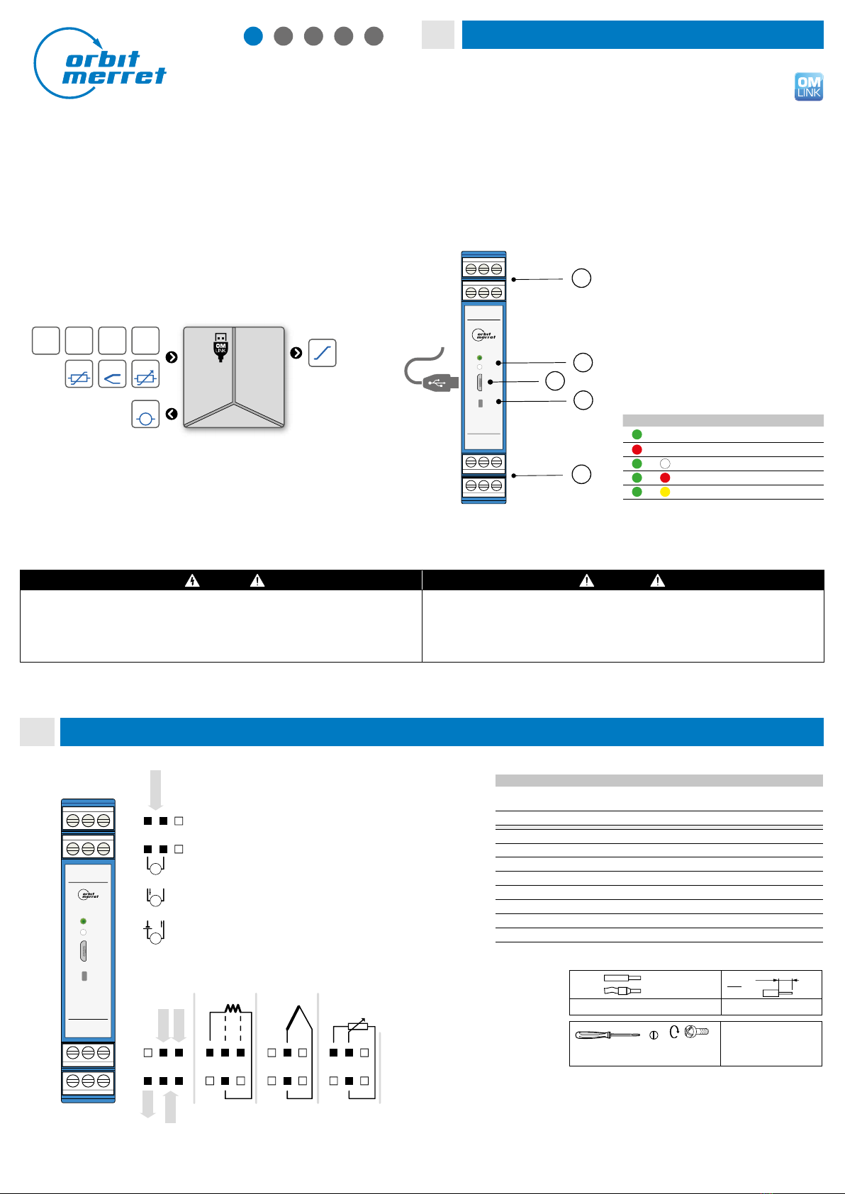
OM Link company communication interface for
operation, setting and update of
instruments. (microUSB)
Watch-dog reset after 500 ms
Calibration at 25°C and 40 % r.h.
ANALOGUE OUTPUT
No. of outputs 1
Type isolated, configurable with a resolution of
10 000 parts, type and range are selectable
in the menu
Non-linearity 0.1 % of FS
TC 15 ppm/°C
Rate response to change of value < 3,5 ms
Ranges 0…10 V, 10…0 V
resistive load < 2,6 kΩ
0…20 mA/20…0
4…20/20…4 mA (active/passive)
compensation of leads' resist. < 600 Ω/12 V
EXCITATION
Fixed voltage 24 VDC/35 mA, isolated
POWER SUPPLY
Power 10…30 VDC/24 VAC, ±10 %, 2.5 VA, PF ≥ 0.4,
ISTP< 40 A/1 ms, isolated
- fuse inside (T500mA)
MECHANIC PROPERTIES
Material PA66, incombustible UL 94 V-0, blue
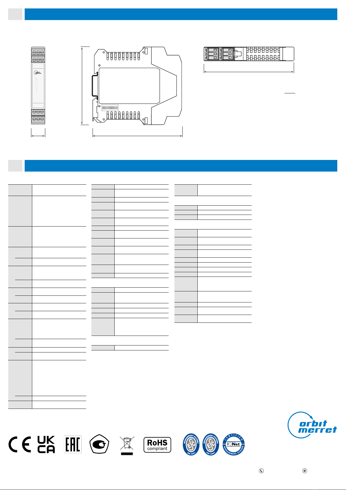
Dimensions 114.5 x 99.0 x 17.5 mm
Installation to DIN rail 35 mm wide
OPERATING CONDITIONS
Connection connector terminal blocks,
section < 2.5 mm2
Stabilization
period within 5 minutes after switch-on
Working temp. -20°…60°C
Working
humidity
< 95 % r.h., non condensing
Storage temp. -20°…85°C
Protection IP20
Construction safety class I
El. safety EN 61010-1, A2
Dielectric
strength
2.5 kVAC for 1 min. between power supply
and signal input
2.5 kVAC for 1 min. between signal input
and outputs
Insulation
resist.*
for pollution degree II, measurement cat. III
power supply > 300 V (PI), 255 V (DI)
Input/outputs > 300 V (PI)
EMC EN 61326-1 (Industrial area)
Seismic
qualification
IEC/IEEE 60980-344 Edition 1.0, 2020, par. 6, 9
Mechanical
resistance
EN 60068-2-6 ed. 2:2008
* PI - Primary insulation, DI - Double insulation
6
Technical data
5
Instrument dimensions and installation
ORBIT MERRET, spol. sr.o.
Vodňanská /
Praha
Czech Republic
+ - [email protected]
Measuring instruments of the OMX UNI series conform to the European regulation //EU and //EU
This product must be installed, connected and used in compliance with prevailing standards and/or installation regulations.
As standards, specications and designs develop from time to time, always ask for conrmation of the information given in this publication.
Side view
mm
inch
Front view
17,5
0.69
Top view
Installation to DIN rail of 35 mm width
4.49
114,5
4.47
114,5
1 2 3 4 5 6 7 8 9 10 11 12
ON
1 2
4 5
3
6
SET
SET
PWR
7 8
10 11
9
12
3.90
99
MINI-TECHDOK - OMX 311UNI - 2022.1 - en
4/4www.orbitmerret.eu
Other Orbit Merret Media Converter manuals
Popular Media Converter manuals by other brands

RKC INSTRUMENT
RKC INSTRUMENT DeviceNet COM-JH instruction manual

TR-Electronic
TR-Electronic CEW582M-00085 Assembly instructions

DTS
DTS CAE-4 System manual

resi-linx
resi-linx digi-MOD RL-DM8000 user guide

Snell Advanced Media
Snell Advanced Media Kudos Pro UHD1000 user manual

tams elektronik
tams elektronik LD-G-32.2 manual