Orbit Merret OMX 103UNI User manual

OMX UNI
DUAL CHANEL USERCONFIGURABLE
UNIVERSAL SIGNAL CONVERTOR
DC VOLTMETER/AMMETER
PROCESS MONITOR
OHM METR
TEMPERATURE DISPLAY FOR Pt //
TEMPERATURE DISPLAY FOR Ni /
TEMPERATURE DISPLAY FOR THERMO COUPLES
DISPLAY FOR LINEAR POTENTIOMETERS
USER MANUAL
Outstanding Measurement Value

2 | USER MANUAL OMX 103UNI
TECHNICAL SPECIFICATIONS
Instruments of the omx series comply with the EU //EU a//EU directive and meet the
following European standards:
EN - Electrical safety
EN - Electrical measuring, control and laboratory equipment
- EMC requirements "Industrial Area"
IEC : , c. Seismic resistance
The device is suitable for unlimited use in agricultural and industrial areas.
SAFETY INSTRUCTIONS
Please read and observe the enclosed safety instructions carefully!
Installation, all operations, maintenance and service must be carried out by qualified personnel only
and in accordance with the enclosed information and safety regulations.
The manufacturer is not responsible for any damage caused by improper installation, configuration,
maintenance and service of the device.
The device must be installed correctly according to the actual application. Improper installation maycause
malfunction, which may result in damage to the unit or an accident.
The device uses dangerous voltage that can cause a fatal accident. The unit must be disconnected from
the power supply before starting troubleshooting (in case of malfunction) or before dismantling the unit.
For safety information, EN - + A must be observed.
Whenremovingorinserting anelectronicscard,observethe safetyinstructionsandfollowtherecommended
procedures. Disconnect the unit from power supply before inserting / extracting any electronics cards.
Do not attempt to repair or modify the device yourself. In case of malfunction the device must be dis-
mounted and submitted to the manufacturer for repair.
These devices should be protected by either individual or shared fuses (circuit breakers)!
Thedevice isnotintendedforinstallationin explosiveareas.Usethe deviceonlyoutside theexplosiveareas.
DANGER WARNING ATTENTION
RISK OF ELECTRIC SHOCK
- Disconnect all power supply and live
wires before servicing.
RISKS ASSOCIATED WITH USE
- Do not use this product in a safety
critical system.
- Do not disassemble, repair or modify
the product.
- Do not use the product outside the
recommended operating conditions.
RISKS ASSOCIATED WITH USE
- Install a 100 mA fuse
Failure to follow this instruction will
result in death or serious injury.
Failure to follow these instructions
may result in death, serious injury, or
damage to the equipment
Failure to observe this precaution
could result in personal injury or
equipment damage.
This electrical equipment may be installed, operated and maintained only by qualified personnel.
ORBIT MERRET assumes no responsibility for any consequences arising from the use of this equipment.

USER MANUAL OMX 103UNI | 3
.CONTENTS
. CONTENTS . . . . . . . . . . . . . . . . . . . . . . . . . . . . . . . . .
. DEVICE DESCRIPTION . . . . . . . . . . . . . . . . . . . . . . . .
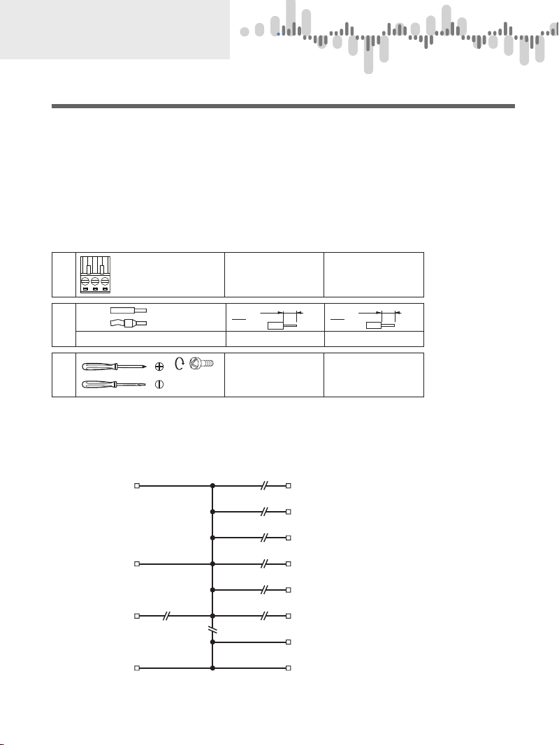
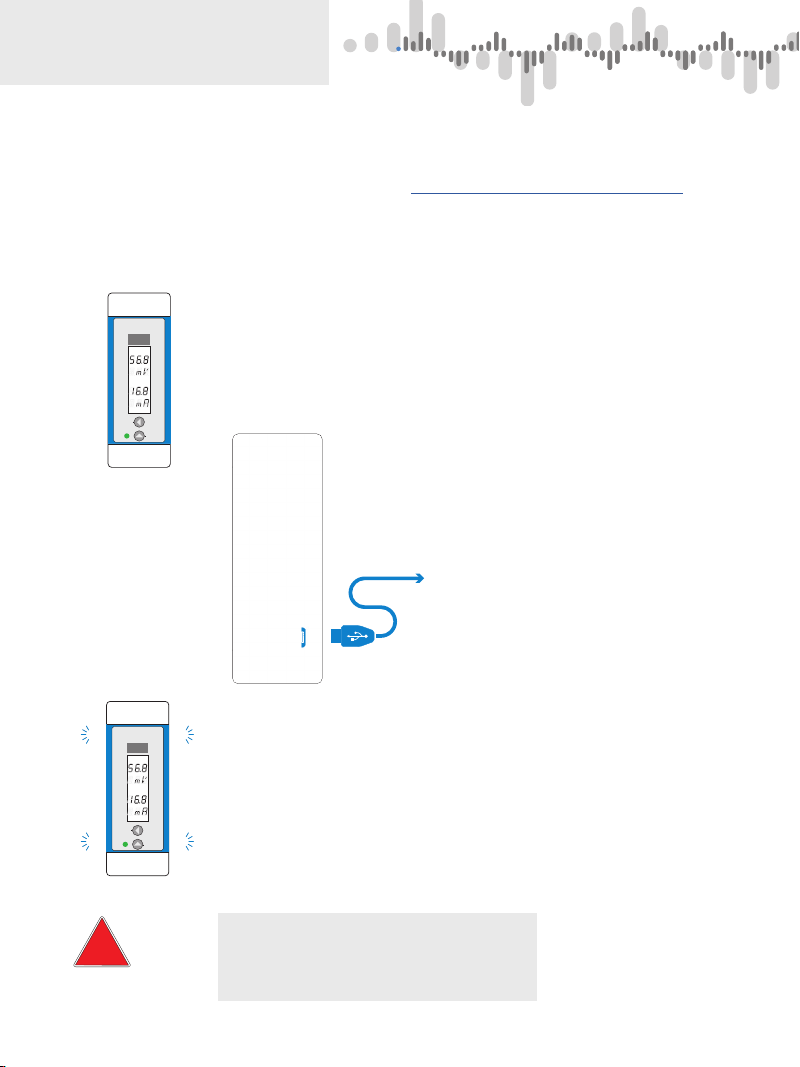
. CONNCECTION . . . . . . . . . . . . . . . . . . . . . . . . . . . . . .
Device connection.. . . . . . . . . . . . . . . . . . . . . . . . . . . . . . . .
OM Link connection via USB . . . . . . . . . . . . . . . . . . . . . .
Connection of individual terminals. . . . . . . . . . . . . . . . .
Examples of sensor connection. . . . . . . . . . . . . . . . . . .
. DEVICE SETTING. . . . . . . . . . . . . . . . . . . . . . . . . . . .
Front panel layout . . . . . . . . . . . . . . . . . . . . . . . . . . . . . . . .
Symbols used in this user manual. . . . . . . . . . . . . . . . .
Setting of decimal point and of negative sign (-). . .
Functions of keys. . . . . . . . . . . . . . . . . . . . . . . . . . . . . . . . .
. “LIGHT” MENU . . . . . . . . . . . . . . . . . . . . . . . . . . . . .
. “LIGHT” menu entry . . . . . . . . . . . . . . . . . . . . . . . . . . . .
Input setting - Type “DC” . . . . . . . . . . . . . . . . . . . . . . . . .
Input setting - Type “PM” . . . . . . . . . . . . . . . . . . . . . . . . .
Input setting - Type “OHM” . . . . . . . . . . . . . . . . . . . . . . .
Input setting - Type “RTD - Pt” . . . . . . . . . . . . . . . . . . . .
Input setting - Type “RTD - Ni” . . . . . . . . . . . . . . . . . . . .
Input setting - Type “RTD - Cu . . . . . . . . . . . . . . . . . . . .
Input setting - Type “T/C”. . . . . . . . . . . . . . . . . . . . . . . . .
Input setting - Type “DU” . . . . . . . . . . . . . . . . . . . . . . . . .
Limits.. . . . . . . . . . . . . . . . . . . . . . . . . . . . . . . . . . . . . . . . . . . .
Analogue output . . . . . . . . . . . . . . . . . . . . . . . . . . . . . . . . .
Language selection . . . . . . . . . . . . . . . . . . . . . . . . . . . . . .
Access password. . . . . . . . . . . . . . . . . . . . . . . . . . . . . . . . .
Device identification. . . . . . . . . . . . . . . . . . . . . . . . . . . . . .
. “PROFI” MENU . . . . . . . . . . . . . . . . . . . . . . . . . . . . .
. “PROFI” menu entry . . . . . . . . . . . . . . . . . . . . . . . . . . .
. “PROFI” menu - INPUT
.. Reset of internal values. . . . . . . . . . . . . . . . . . . . .
.. Input Configuration . . . . . . . . . . . . . . . . . . . . . . . .
.. Input setting.. . . . . . . . . . . . . . . . . . . . . . . . . . . . .
.. Input setting . . . . . . . . . . . . . . . . . . . . . . . . . . . . .
.. Functionality of external control inputs . . . . .
. “PROFI” menu - CHANNELS
.. Channel parameters
(filters, decimal point, units) . . . . . . . . . . . . . . . .
.. Channel parameters . . . . . . . . . . . . . . . . . . . . .
.. Math functions . . . . . . . . . . . . . . . . . . . . . . . . . . . .
.. MIN/MAX value evaluation . . . . . . . . . . . . . . . . .
. “PROFI” menu - OUTPUT
.. Limits. . . . . . . . . . . . . . . . . . . . . . . . . . . . . . . . . . . . . .
.. Data output selection . . . . . . . . . . . . . . . . . . . . . .
.. Analogue output selesction . . . . . . . . . . . . . . . .
.. LCD bakclight option. . . . . . . . . . . . . . . . . . . . . . .
. “PROFI” menu - SERVICE
.. Real Time Clock setting (RTC) . . . . . . . . . . . . .
.. Factory settings restoration . . . . . . . . . . . . . . . .
.. Language selection. . . . . . . . . . . . . . . . . . . . . . . .
.. New access password. . . . . . . . . . . . . . . . . . . . .
.. Device identification . . . . . . . . . . . . . . . . . . . . . . .
. “USER” MENU . . . . . . . . . . . . . . . . . . . . . . . . . . . . .
. Configuration of “USER” menu . . . . . . . . . . . . . . . . .
. COLD JUNCTION COMPENSATION . . . . . . . . . . . . .
. DATA PROTOCOL . . . . . . . . . . . . . . . . . . . . . . . . . . .
. ERORR CODES. . . . . . . . . . . . . . . . . . . . . . . . . . . . . .
. TABLE OF CHARACTERS . . . . . . . . . . . . . . . . . . . . .
. TECHNICAL DATA.. . . . . . . . . . . . . . . . . . . . . . . . . . .
. DIMENSIONS AND MOUNTING INSTRUCTIONS . .
. WARRANTY CERTIFICATE . . . . . . . . . . . . . . . . . . . .

4 | USER MANUAL OMX 103UNI
. DEVICE DESCRIPTION
2.1 Description
The OMX series are DIN rail mountable programmable transducers designed for maximum convenience
and user convenience. Available versions are UNI (universal), DC (DC current andvoltage), PWR (power), UQC
universal quadrature counter and T (load cell).
Type OMX UNI is a multifunctional dual-input device with the possibility of configuration for different
input variants easily configurable in the device menu.
The OMX is based on a single-chip microcontrollerwith -bit A / D converter, which provides very good
accuracy, stability and easy operation.
VERSIONS AND MEASURING RANGES
UNI or individual isolated inputs
DC ±/±/ mV; ±/±/± V; ±/± mA
PM ±/± mA/… mA; ±/±/± V
OHM …/// /…,/// k
Pt Pt ///
Cu Cu /
Ni Ni /
T/C J/K/T/E/B/S/R/N/L
DU Linear potentiometer (min. )
CONFIGURABLE PROJECTION
To be selected: input type and measuring range
Configuration: standard - projection setting for both endpoints of input range
teach-in - projected endpoints of input range can be assigned to any two values of
(unknown) input signal.
manual - projection setting for both set endpoints of input range
Projection: -…
ANALOGUE OUTPUT
Type: isolated, user configurable, bit resolution, rate < ms
Quantity: …
Ranges: …// V, ± V, … mA, /… mA
COMPENSATION
Leads (RTD, OHM): -wire compensation can be realised in the device menu
Probe (RTD): internal connection (resistance of leads inside the temperature probe)
Cold junction (T/C): manual or automatic. Selection of thermocouples as well as the cold junction
compensation can be made in the menu. This could be set by user, or be automatic
(temperature of screw terminals)
LINEARIZATION
Linearization:* linear interpolation in points (possible only with Link SW)
DIGITAL FILTERS
Floating average: from … measurements
Exponent. average: from … measurements
Arithmetic average: from … measurements
Rounding: setting the rounding step for the display
* only for input types DC, PM, DU

USER MANUAL OMX 103UNI | 5
.DEVICE DESCRIPTION
MATHEMATIC FUNCTIONS
Min/Max. vale: preserves min./max. values reached during a measurement
Tare: is used to reset the displayto zero even when the input signal does not correspond to zero
Peak value: display projects only max. or min. value
Math operations: polynomial, /x, logarithmic, exponential, power, root, sin x
and mathematic operations between inputs - sum, multiple and ratio
EXTERNAL CONTROLS
Lock: front panel keys are blocked
Hold: freezing the display/instrument
Tare: applying tare/resetting tare
Resetting Min/Max: resetting of Min/Max value
■Controls
Device is controlled by two keys located on the front panel or by OM Link SW. Settings can be realised in three
levels.
LIGHT Simplified menu
- contains only the most essential menu items that are necessary for setting up the device.
It can be password protected.
PROFI Complete menu
- contains all menu items and it can be password protected
USER User define menu
-somemenuitem(LIGHT/PROFI) canbe includedintothismenu.Accessrightstoeachmenu
may be assigned (to view only, or to edit)
- no password access
All configuralbe parameters are stored in EEPROM memory (remain stored even after power off).
All settings may be realised via PC' USB interface using our free to download SW called
OM Link.
OM Link „Basic“ provides for connection of ORBIT MERRET device to PC. OM Link also makes it possible
for the measured values to be visualised and archived in the PC. „OM Link Standard“ does exactly the sam
without the number of OM devices being limited.
■Options
Comparators (in the form of relays oropen collectors), are designed for monitoring one to six limitvalues. The
user can select the limit mode: LIMIT / DOSE / FROM-TO. Limits have adjustable hysteresis in the full range
of the displayed value and an optional switch-on delay in the range of … . s. Reaching the set limits is
signalled by LEDs and at the same time by actuating the relevant relay.
Data outputs Due to their speed and accuracy, data outputs are suitable for transferring measured data to
other displays, or directly to control systems. We offer isolated RS and RS data outputs with ASCII,
DIN MessBus and MODBUS RTU protocol, Profibus DP communication card or Ethernet.

6 | USER MANUAL OMX 103UNI
. DEVICE CONNECTION
3.1 Connection
Power supply leads should not be in the vicinity of the low voltage input signals.
Contactors, high power motors and other power elements should not be in the vicinity of this device.
Input signal leads (measured value) should be sufficiently far away from all power lines and appliances. If this
cannot be ensured, a grounded shielded cable (terminal E) must be used.
This device has successfully passed tests according to the industry standards, however we still recommend
that you observe the above guidelines.
■Leads connection
Connector pitch 3,5mm 5mm
mm
in
mm
in.
8
0.32
mm
in.
8
0.32
mm2/AWG 0,05…1,5/30…14 0,05…2,5 / 30…12
1,5Nm
13.2 lb-in
Ø 2,5mm
0.1 in
Ø 3,5mm
0.14 in
■Galvanic isolation
Analogue input
Digital inputs
Service interface
USB
Power supply
Analogue output
Output- Relay
optional
Output- Open collector
optional
Data output
optional
Ethernet
optional
OM Bus
4 kV
3,75 kV
3,75 kV
4 kV
1,5 kV
3 kV
Efcitation
60 V
60 V
Digital output - Ready

USER MANUAL OMX 103UNI | 7
.DEVICE CONNECTION
ABC
++−
GND
AO Voltage
AO Current
AO 1
POWER
+
−
L
E
N
ETHERNET
USB
EXT. 2
EXT. 1
12 13 14 16 1715
Card slot B1 Card slot B2
1
2
3
Channel 2
23 22 21 19 1820
FED BACFED BAC
Card slot A2
ABC E FD
+
−
+++
GND
Shielding
INPUT 1
INPUT 2
INPUT 3
S+ S-
S-
ES+
E+
ES+ ES-
E-
E-
Channel 1
23 22 21 19 1820
TxD
RxD
GND
ABC
1
ABCDEF
2
Data output
Limits
E 1
C 1
E 2
C 2
+
−
+++
GND
Shielding
INPUT 1
INPUT 2
INPUT 3
S+ S-
S-
ES+
E+
ES+ ES-
E-
E-
Channel 2
Rx/Tx-
Rx/Tx+
ABC
RS 232 RS 485
445679 12 13 14 16 1715
1
2
3ABC
89
10 11
4567
Excitation
+
−
OC Ready
8 9 10 11
+
−
OM Bus
+−
Shielding
Marking of outputs in the menu
A2 AV. 2 • RS. 1 • LIM. 1, 2
B1 AV. 3 • LIM. 3, 4
B2 AV. 4 • RS. 2 • LIM. 5, 6

8 | USER MANUAL OMX 103UNI
. DEVICE CONNECTION
■Setting via USB interface
Use of OM Link software is recommended for more convenient setting of the converter. Use a USB to micro
USB cable to connect to your computer.
The OM Link SW can be downloaded free of charge at www.merret.cz/produkty/software/om-link
There is a microUSB connector located under the front cover. To access the connector, the cover needs to
be removed.
USB cable connection
Gently pry open the front cover in the areas indicated in the picture and
remove it.
Connect to PC using a USB to microUSB cable and
launch OM Link SW. Make sure input signal is not
connected!
12
INPUT
OUTPUT
Ԩ
Ԩ
Ԩ
Ԩ
After disconnecting from PC reinstall the front cover
BothMicroUSBand OMLinkconnectorsaregalvanicconnected
to the input!
It is necessary to use an isolated USB cable if the input signal
is connected
RISK OF COMPUTER DAMAGE
USB
micro
INPUT
OUTPUT
ǖ
12
INPUT
OUTPUT
ȦȦ
Ԩ
Ԩ
ȦȦ
Ԩ
Ԩ
!

USER MANUAL OMX 103UNI | 9
.DEVICE CONNECTION
■DC input signal connection
This input card can be inserted also into Channel 2 slot
■Process Monitor (PM) input signal connection
This input card can be inserted also into Channel 2 slot
■OHM, Pt, Ni, Cu input signal connection
This input card can be inserted also into Channel 2 slot
■Thermocouple (T/C) input signal connection
This input card can be inserted also into Channel 2 slot
■Linear potentiometer (DU) connection
This input card can be inserted also into Channel 2 slot
Linear potentiometer, R >
In case of 2-wire or 3-wire connection it is
essential to interconnect unconnected
terminals (14+15/16+17 or14+15).
This rule also applies to Channel 2
i
Range DC
±30/ ±60/±1000 mV Input 3 14
±20 /±40 /±80 V Input 2 13
±90/ ±180 mA Input 1 11
+
+
+
+
−
17
16
15
13
12
14
+-
+
+
+
+
−
17
16
15
13
12
14
++
+
+
−
17
16
15
13
12
14
+-
+
Range PM
±5/ ±20 /4…20 mA Input 1 11
±5 /±10 V Input 2 13
+
+
+
−
17
16
15
13
12
14
++
+
+
−
17
16
15
13
12
14
+-
+
ES-
ES+
S-
S+
E-
E+
S-
E-
ES+
17
16
15
13
12
14
+
+
+
+
−
17
16
15
13
12
14
+
17
16
15
13
12
14

10 | USER MANUAL OMX 103UNI
. DEVICE CONNECTION
■Analogue output connection
This output card can be inserted into A and B slots
B
C
A
GND
AO Voltage
AO Current
+
−
+
■Data output connection
This output card can be inserted into A and B slots
■Relay output and Open collector output connection
This output card can be inserted into A, B and B slots
■Sensor excitation connection
Sensor excitation is of fixed voltage. It is galvanic isolated.
For connection examples see page
RS 232 RS 485
• One OMX to one PC communication
• maximum cable length is not to exceed m
• twisted cable AWG /, mmis recommended
•up to OMX can be connected to one PC
• maximum cable length is not to exceed m
• twisted cable AWG /, mmis recommended
• the last device on the line must have a terminating
resistor connected to the RS card, a shorting jumper
must be fitted
Range PM
0…5 mA AO - Current B
0…20 mA AO - Current B
4…20 mA AO - Current B
0…2 V AO - Voltage A
0…5 V AO - Voltage A
0…10 V AO - Voltage A
±10 V AO - Voltage A
B
C
AGND
TxD
RxD
B
C
A
Rx/Tx-
Rx/Tx+
E
F
D
1
2
C
B
A
E
F
D
1
2
C
B
A
E2
C2
E1
C1
24 VDC/1 W
4
6
7
5
+
−+
−
8
10
11
9
+
−

USER MANUAL OMX 103UNI | 11
.DEVICE CONNECTION
■External controls connection
- inputs are controlled by dry
contact
- inputs are controlled by VDC
■Connection of signal Ready
Output is active is the system is ok
(Open collector VDC/ mA)
■Connection of OM Bus
Wires are interchangeable, their
polarity is unimportant
■Power supply
EXT. 1
EXT. 2
+
12
24 VDC/1 W
4
6
7
5
+
−+
−
8
10
11
9
+
−
4
6
7
5
+
−
8
10
11
9
+
−
Ready
4
6
7
5
+
−
8
10
11
9
+
−
OM Bus
2
1
3E
N
+
−
L
!
Voltage ranges are defined by hardware, not user selectable
Always check the device label for correct voltage before
connecting the power supply.
Grounding wire must be connected to terminal "E" at all times.
RISK OF ELECTRIC SHOCK

12 | USER MANUAL OMX 103UNI
. DEVICE CONNECTION
+
-
4
6
7
5
+
−+
−
8
10
11
9
+
−
+
+
+
−
17
16
15
13
12
14
+
12
13
14
16
17
15
+
+
+
+
−
4
6
7
5
+
−+
−
8
10
11
9
+
−
+
-
+
4
6
7
5
+
−+
−
8
10
11
9
+
−
+
-
+
+
+
+
−
17
16
15
13
12
14
+
■Example connection of a -wire sensor with current signal output
powered by instrument’s excitation
-wire sensor with … mA output powered via the
current loop by the convertor’s own V sensor excitation
■Example connection of a -wire sensor with current signal output
powered by instrument’s excitation
-wire sensor with … mA output powered by the
convertor’s own V sensor excitation
■Example connection of a -wire sensor with voltage signal output
powered by instrument’s excitation
-wire sensor with … V output powered by the
convertor’s own V sensor excitation

USER MANUAL OMX 103UNI | 13
.DEVICE CONNECTION

14 | USER MANUAL OMX 103UNI
. DEVICE SETTING
SETTING
LIGHT
For trained users
Contains items necessary for basic instrument setting
Password protected access
Items from LIGHT menu can be incorporated into USER menu
Linear menu structure
SETTING
PROFI
For experienced users
Contains all menu items
Password protected access
Items from PROFI menu can be incorporated into USER menu
Tree menu structure
SETTING
USER
To be used by machine operators
Menu items are selected by user (from Profi/Light menus) as needed
Access is not password protected
Optional menu structure either tree (PROFI) or linear (LIGHT)

USER MANUAL OMX 103UNI | 15
.DEVICE SETTING
4.1
Setting
Besidesthe possibilityofconfigurationfromPCvia themicroUSBinterface,theOMXcanalso beconfigured
by two control keys located on the front panel. Configuration can be performed in one of these three modes
LIGHT Basic programming menu
- contains only menu items essential for basic settings and can be numeric password protected
PROFI Detailed programming menu
- contains all menu items and can be protected by numeric password
USER Customised programming menu
- any menu item can be selected to form USER menu. These items can have different access
rights (viewable or editable)
- no password protection
Complete device settings can be done via USB connection. The SW is freely available at www.orbit.merret.
cz. Another possibility to connect to PC is via RS or RS data output card, provided the OMX is
fitted with one (optional).
Version „Basic“ of OM Link SW enables you to connect one OMX to one PC. It is possible to visualise and
also record measured data on PC. There is no quantity restriction on the number of OM devices connected
to one PC in SW OM Link "Standard".
■Description of the display and control buttons
12
INPUT
OUTPUT
1
3
46
5
2
Input value
plus 3-characters used for displaing units
Output value
plus 3-characters used for displaing units
Comparator status - red LED
ON digit is on
OFF digit is o
OFF digit is ashing, comprator action is
restricted (time delay)
Device status - green LED
ON LED is on
ON LED is asing - error message
OFF LED is o
Tare indication - Tare
when Tare is active, sign “INPUT” ashes
Control keys

16 | USER MANUAL OMX 103UNI
. DEVICE SETTING
■Symbols used in this user manual
DC PM DU
OHM RTD T/C indicates settings for the given type of instrument
DEF default settings
286a taller and flashing digit indicates which position is being edited
MIN inverted triangle indicates a menu item which can be included into USER menu
CO N .brokenline indicatesadynamicmenuitem,i.e. itisavailableonlyinparticularselection/version
press both keys simultaneously
s press both keys simultaneously for more than seconds
if this key is pressed, the newly set parameter will NOT be stored
if this key is pressed, the newly set parameter WILL be stored
continues on page (go to page )
■Decimal point and the negative sign
Decimal point
Position of the decimal point is edited by key When the highest decade is exceeded, the entire display starts
to flash. Position is then determined by pressing the key.
Negative sign
Setting of the negative sign is performed bykey on the higher decade.When editing this item, figures change
in a numeric sequence , , …, , „-“, ,

USER MANUAL OMX 103UNI | 17
.DEVICE SETTING
■Functions of control keys
■Flow chart of measured signal
Key symbol Measurement Menu Setting of number/selection
switching inputs/outputs back to previous level go to higher decade
access into USER menu go to next item go up
access into LIGHT menu confirm selection confirm setting/selection
2s access into PROFI menu
Chan. A
Filter
Mat.Fce.
Relays
Analog
Memory
Min/Max
Data
Linearization
Inputs
Linearization Displaj

18 | USER MANUAL OMX 103UNI
MENU LIGHT.
SETTING
LIGHT
For trained users
Contains items necessary for basic instrument setting
Password protected access
Items from LIGHT menu can be incorporated into USER menu
Linear menu structure
5.0 Setting “LIGHT”
LIGHT Basic programming menu
• contains menu items essential for basic instrument setting and is protected by user defined
numeric password
• designed for trained users
■Entry into “LIGHT” menu
• entering LIGHT menu
• password protected access
• in case the access password in menu item SER. > C. M. > LIG. is set to , access is granted
without the need to enter any password. This is the default setting.

USER MANUAL OMX 103UNI | 19
.MENU LIGHT
E 4.MO. 2
Second input (optional)
PMT. 2
142 PAS. 0
Access password
E 4.
Input mode
MO.1
Input type
PMT. 1
No. of inputs
IN .1INP.
4-WCO .1 FL . P.ZO .A
OHMRTD
EX .1CO .1 0C.J.1 FO .A FL. P.
Projection and connection
T/C
0MI.1 100MA.1 FO .A FL. P.
PMDC DUOHM
Comparators (optional)
Analogue output (optional)
T.A .1 4-20
L.1 33 .3 L.2 75
A.L.1 A. H.1 1000
Calibration - only for “DU”
T.L.1 YES T.H.1 YES
DU
MNU LIG .
Type of Menu
Language
LN G .CZ
Identification
ID .YES OMX 102UNI
Model/Type
Return into measuring
mode
14284-006 PM
SW version input
Factory settings reset
SET.YES
New password
P.LI. 0
Store settings
SAV.YES
If there is a pause during configuration exceeding 60s, the
device automatically exits configuration mode and returns
into measuring mode.
DEF Default setting
Password 0
Menu LIGHT
USER menu Off
i

20 | USER MANUAL OMX 103UNI
. MENU LIGHT
142. 8
PAS. 0
INP.IN .1 IN . 2
Parameter Display User Description
Number of inputs INP. Number of active inputs
One input IN.1. Input active
Two inputs IN.2 Inputs and active DEF
Example settingNo. of inputs - 1 input > IN.1
IN.2 IN.1 T. 1
Parameter Display User Setting Description
Password PAS.0 …999 Enter password to access menu
Access unrestricted 00Free access to menu
•Password item skipped. First menu item
appears
Access protected by
password 11 …999 Menu access is protected by numeric
password
Example settingPassword - 42 > 42
0120212223242INP.
→
→
→
→
iThis dynamic item only appears in the -input version
Table of contents
Other Orbit Merret Transmitter manuals