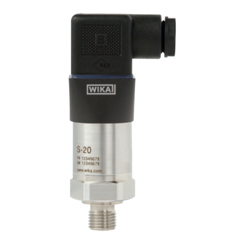
WIKA T12 Series User manual

D
GB
Operating instructions
Betriebsanleitung
Head mounting version Rail mounting version
model T12.10 model T12.30
Temperature transmitter model T12
Temperatur-Transmitter Typ T12

2
D
GB Operating instructions model T12
Page3 - 38
Betriebsanleitung Typ T12
Seite 39 - 71
©WIKAAlexanderWiegandSE&Co.KG2010
Priortostartinganywork,readtheoperatinginstructions!
Keepforlateruse!
VorBeginnallerArbeitenBetriebsanleitunglesen!
ZumspäterenGebrauchaufbewahren!
3211517.0707/2010GB/D
WIKAoperatinginstructionstemperaturetransmitterT12

GB
3211517.0707/2010GB/D
WIKAoperatinginstructionstemperaturetransmitterT12 3
Contents
1. General information 4
2. Safety 6
3. Specications 13
4. Design and function 14
5. Transport, packaging and storage 15
6. Commissioning, operation 16
7. WIKA T12 conguration software 25
8. Notes for mounting and operating in
hazardous areas (Europe) 27
9. Further country-specic approvals 32
10. Maintenance 32
11. Faults 33
12. Return and disposal 34
Appendix 1: CSA Installation drawing 36
Appendix 2: FM Installation drawing 37
Appendix 3: EC Declaration of conformity 38
Contents

GB
3211517.0707/2010GB/D
4 WIKAoperatinginstructionstemperaturetransmitterT12
1. General information
■
Thetemperaturetransmitterdescribedintheoperatinginstruc-
tionshasbeendesignedandmanufacturedusingstate-of-the-
arttechnology.Allcomponentsaresubjecttostringentquality
andenvironmentalcriteriaduringproduction.Ourmanagement
systemsarecertiedtoISO9001andISO14001.
■
Theseoperatinginstructionscontainimportantinformationon
handlingthetemperaturetransmitter.Workingsafelyrequiresthat
allsafetyinstructionsandworkinstructionsareobserved.
■
Observethelocalaccidentpreventionregulationsandgeneral
safetyregulations,ineectforthetemperaturetransmittersrange
ofuse.
■
Theoperatinginstructionsarepartoftheinstrumentandmustbe
keptintheimmediatevicinityofthetemperaturetransmitterand
readilyaccessibletoskilledpersonnelatanytime.
■
Skilledpersonnelmusthavecarefullyreadandunderstoodthe
operatinginstructions,priortobeginninganywork.
■
Themanufacturersliabilityisvoidinthecaseofanydamage
causedbyusingtheproductcontrarytoitsintendeduse,
non-compliancewiththeseoperatinginstructions,assignmentof
insucientlyqualiedskilledpersonnelorunauthorisedmodica-
tionstothetemperaturetransmitter.
■
Thegeneraltermsandconditions,containedinthesales
documentation,shallapply.
■
Subjecttotechnicalmodications.
■
Furtherinformation:
-Internetaddress: www.wika.de/www.wika.com
-Relevantdatasheet: TE12.03
-Applicationconsultant: Tel.: (+49)9372/132-0
Fax: (+49)9372/132-406
E-Mail: inf[email protected]
1. General information

GB
3211517.0707/2010GB/D
WIKAoperatinginstructionstemperaturetransmitterT12 5
Explanation of symbols
WARNING!
...indicatesapotentiallydangeroussituation,whichcan
resultinseriousinjuryordeath,ifnotavoided.
CAUTION!
...indicatesapotentiallydangeroussituation,whichcan
resultinlightinjuriesordamagetoequipmentorthe
environment,ifnotavoided.
Information
...pointsoutusefultips,recommendationsandinforma-
tionforecientandtrouble-freeoperation.
DANGER!
...identieshazardscausedbyelectricalpower.Should
thesafetyinstructionsnotbeobserved,thereisariskof
seriousorfatalinjury.
WARNING!
...indicatesapotentiallydangeroussituationina
potentiallyexplosiveatmosphere,resultinginserious
injuryordeath,ifnotavoided.
1. General information

GB
3211517.0707/2010GB/D
6 WIKAoperatinginstructionstemperaturetransmitterT12
2. Safety
WARNING!
Beforeinstallation,commissioningandoperation,
ensurethattheappropriatetemperaturetransmitterhas
beenselectedintermsofmeasuringrange,designand
specicmeasuringconditions.
Seriousinjuriesand/ordamagecanoccurshouldthese
notbeobserved.
WARNING!
ThisisProtectionClass3equipmentforconnectionatlow
voltages,whichareseparatedfromthepowersupplyor
voltagebygreaterthan50VACor120VDC.Preferably,
aconnectiontoanSELVorPELVcircuitisrecommended;
alternativelyprotectivemeasuresfromHD60346-4-41
(DINVDE0100-410).
AlternativelyforNorthAmerica:
Theconnectioncanbemadeinlinewith"Class2
Circuits"or"Class2PowerUnits"inaccordancewith
CEC(CanadianElectricalCode)orNEC(National
ElectricalCode)
Furtherimportantsafetyinstructionscanbefoundinthe
individualchaptersoftheseoperatinginstructions.
2.1 Intended use
ThemodelT12temperaturetransmitterisauniversal,congurable
transmitterforusewithresistancethermometers(RTD),thermocoup-
les(TC)aswellasresistanceandvoltagesources.
Thetemperaturetransmitterhasbeendesignedandbuiltsolelyfor
theintendedusedescribedhere,andmayonlybeusedaccordingly.
2. Safety

GB
3211517.0707/2010GB/D
WIKAoperatinginstructionstemperaturetransmitterT12 7
Thetechnicalspecicationscontainedintheseoperatinginstructions
mustbeobserved.Shouldtheinstrumentbeimproperlyhandled
oroperatedoutsideofitstechnicalspecications,itshouldbeshut
downimmediatelyandinspectedbyanauthorisedWIKAservice
engineer.
Ifthetemperaturetransmitteristransportedfromacoldintoawarm
environment,theformationofcondensationmayresultintheinstru-
mentmalfunctioning.Beforeputtingitbackintooperation,waitforthe
instrumenttemperatureandtheroomtemperaturetoequalise.
Themanufacturershallnotbeliableforclaimsofanytypebasedon
operationcontrarytotheintendeduse.
2.2 Personnel qualication
WARNING!
Risk of injury should qualication be insucient!
Improperhandlingcanresultinconsiderableinjuryto
personnelanddamagetoequipment.
■ Theactivitiesdescribedintheseoperatinginstruc-
tionsmayonlybecarriedoutbyskilledpersonnelwho
havethequalicationsdescribedbelow.
■ Keepunqualiedpersonnelawayfromhazardous
areas.
Skilled personnel
Skilledpersonnelareunderstoodtobepersonnelwho,basedontheir
technicaltraining,knowledgeofmeasurementandcontroltechnology
andontheirexperienceandknowledgeofcountry-specicregula-
tions,currentstandardsanddirectives,arecapableofcarryingout
theworkdescribedandindependentlyrecognisingpotentialhazards.
Specialoperatingconditionsrequirefurtherappropriateknowledge,
e.g.ofaggressivemedia.
2. Safety

GB
3211517.0707/2010GB/D
8 WIKAoperatinginstructionstemperaturetransmitterT12
2.3 Additional safety instructions for instruments with ATEX
approval
WARNING!
Non-observanceoftheseinstructionsandtheircontents
mayresultinthelossofexplosionprotection.
WARNING!
Observetheapplicableregulationsfortheuseof
Ex-class
instruments(e.g.:EN61326-1:2006,EN
61326-2-3:2006,
EN50014:1992,EN50020:1994,EN50284:1997,
EN50021:1999)
■
Donotusetransmitterswithanydamagetothe
exterior!
Thetransmitter,theprogrammingadapter
(ProgrammingUnitPU348)andthePCmustbeused
outsidethehazardousareaduringconguration!
2.4 Special hazards
WARNING!
Observetheinformationgivenintheapplicabletype
examinationcerticateandtherelevantcountry-specic
regulationsforinstallationanduseinpotentiallyexplo-
siveatmospheres(e.g.IEC60079-14,NEC,CEC).
Non-observancecanresultinseriousinjuryand/or
damagetoequipment.
Foradditionalimportantsafetyinstructionsforinstur-
mentswithATEXapprovalseechapter"2.3Additional
safetyinstructionsforinstrumentswithATEXapproval".
WARNING!
Thefunctionalgalvanicisolationpresentintheinstrument
doesnotensuresucientprotectionagainstelectrical
impulsesinthesenseofEN61140.
2. Safety

GB
3211517.0707/2010GB/D
WIKAoperatinginstructionstemperaturetransmitterT12 9
WARNING!
Forhazardousmediasuchasoxygen,acetylene,
ammableortoxicgasesorliquids,andrefrigeration
plants,compressors,etc.,inadditiontoallstandard
regulations,theappropriateexistingcodesorregulations
mustalsobefollowed.
WARNING!
Toensuresafeworkingontheinstrument,theoperator
mustensure
■
thatsuitablerst-aidequipmentisavailableandaidis
providedwheneverrequired.
■
thattheoperatingpersonnelareregularlyinstructedin
alltopicsregardingworksafety,rstaidandenviron-
mentalprotectionandknowtheoperatinginstructions
and,inparticular,thesafetyinstructionscontained
therein.
WARNING!
Whenworkingduringarunningprocessoperation,
measurestopreventelectrostaticdischargefromthe
connectingterminalsshouldbetaken,asadischarge
couldleadtotemporarycorruptionofthemeasured
value.
WhenmountingaT12.10transmitterintoaeldenclos-
ure,separatefromthetemperaturesensor(transmitter
mountedawayfromtheconnectionheadofthethermo-
meter)itisrecommendedthatconnectioncableswith
shieldingbetweensensorandtransmitterareused,and
thattheshieldingisconnectedtoearthatoneend.
2. Safety

GB
3211517.0707/2010GB/D
10 WIKAoperatinginstructionstemperaturetransmitterT12
DANGER!
Danger of death caused by electric current
Uponcontactwithliveparts,thereisadirectdangerof
death.
■
Electricalinstrumentsmayonlybeinstalledand
mountedbyskilledelectricalpersonnel.
■
Operationusingadefectivepowersupplyunit(e.g.
shortcircuitfromthemainsvoltagetotheoutput
voltage)canresultinlife-threateningvoltagesatthe
instrument!
WARNING!
Residualmediaindismountedinstrumentscanresultina
risktopersons,theenvironmentandtheequipment.Take
sucientprecautionarymeasures.
DonotusethisinstrumentinsafetyorEmergencyStop
devices.Incorrectuseoftheinstrumentcanresultin
injury.
Shouldafailureoccur,aggressivemediawithextremely
hightemperatureandunderhighpressureorvacuum
maybepresentattheinstrument.
2. Safety

GB
Model
Pin
assignment
Foran
explanation
ofsymbols,
seepage12
Outputsignal
Powersupply
Sensor,Pt100
orRTD
3211517.0707/2010GB/D
WIKAoperatinginstructionstemperaturetransmitterT12 11
2.5 Labelling / safety labels
Product label
■
Headmountingversion,modelT12.10
2. Safety
Yearof
manufacture

GB
3211517.0707/2010GB/D
12 WIKAoperatinginstructionstemperaturetransmitterT12
■
Railmountingversion,modelT12.30
2. Safety
Model
Yearof
manufacture
-Sensor,Pt100
orRTD
-Powersupply
-Outputsignal
Pin
assignment
Explanation of symbols
Beforemountingandcommissioningtheinstru-
ment,ensureyoureadtheoperatinginstructions!
CE, Communauté Européenne
Instrumentsbearingthismarkcomplywiththerelevant
Europeandirectives.
ATEX European Explosion Protection Directive
(Atmosphère=AT,explosible=Ex)
Instrumentsbearingthismarkcomplywiththerequi-
rementsoftheEuropeanDirective94/9/EC(ATEX)on
explosionprotection.

GB
3211517.0707/2010GB/D
WIKAoperatinginstructionstemperaturetransmitterT12 13
3. Specications
Specications Model T12.10.xxx Model T12.30.xxx
Ambient/storage
temperature
■
Standardrange
■
Extendedrange
-40...+85°C
-50...+85°C1) -20...+70°C
-
Climate class
perDINEN60654-1
Cx(-40…+85°C,5%up
to95%rel.airhumidity)
Bx(-20…+70°C,5%
upto95%rel.humidity)
Maximum permissible
humidity
perDINIEC68-2-30Var.2
100%relativehumidity
(unlimitedwithinsulated
sensorconnectionwires),
moisturecondensation
permissible
90%
relativehumidity
Vibration
10…2000Hz5gDINIEC68-2-6
Shock DINIEC68-2-2730g
Salt mist DINIEC68-2-11
Case material Plastic,PBT,glassbre
reinforced
Plastic
Ingress protection
perIEC60529/EN60529
IP00 IP20
1)withoutexplosionprotection
ForfurtherspecicationsseeWIKAdatasheetTE12.03andthe
orderdocumentation.
Forfurtherimportantsafetyinstructionsforoperationin
hazardousareasseechapter"10.Notesformounting
andoperatinginhazardousareas".
3. Specications

GB
3211517.0707/2010GB/D
14 WIKAoperatinginstructionstemperaturetransmitterT12
4. Design and function
4.1 Description
ThetemperaturetransmittermodelT12.x0isusedforconvertinga
resistancevalueoravoltagevalueintoaproportionalcurrentsignal
(4...20mA).
Thusthesensorsarepermanentlymonitoredfortheirfault-free
operation.
Theanaloguesignalistransmittedtoaseries-connectedlogicunit
(e.g.aPLCoraswitchcontact)whereitismonitoredforanydeviation
overamaximumvalueorbelowaminimumvalue.
Forfailuremonitoring,thelogicunitmustbecapableofrecognising
bothHIalarms(adjustablefrom21...23.0mA)andLOalarms
(3.6mA).Theelectricalcomponentsofthetransmitteraremountedin
aplasticcaseandfullyencapsulated.
Thetemperaturetransmittermeetstherequirementsfor:
■
Explosionprotection(dependingontheversion)
■
Electromagneticcompatibilityinaccordancewith2004/108/EG
■
SignallingattheanalogueoutputinaccordancewithNAMUR
recommendationNE43
4.3 Scope of delivery
Cross-checkscopeofdeliverywithdeliverynote.
4. Design and function

GB
3211517.0707/2010GB/D
WIKAoperatinginstructionstemperaturetransmitterT12 15
5. Transport, packaging and storage
5.1 Transport
Checkinstrumentforanydamagethatmayhavebeencausedby
transport.Obviousdamagemustbereportedimmediately.
5.2 Packaging
Donotremovepackaginguntiljustbeforemounting.
Keepthepackagingasitwillprovideoptimumprotectionduringtrans-
port(e.g.changeininstallationsite,sendingforrepair).
5.3 Storage
Permissible conditions at the place of storage:
■
Storagetemperature:-40...+85°C
■
Humidity:95%relativehumidity
Avoid exposure to the following factors:
■
Directsunlightorproximitytohotobjects
■
Mechanicalvibration
■
Soot,vapour,dustandcorrosivegases
5. Transport, packaging and storage

GB
3211517.0707/2010GB/D
16 WIKAoperatinginstructionstemperaturetransmitterT12
Mounting example:
3173801.A
Mounting on the measuring insert
Mountthetransmitteronthecircularplateofthemeasuringinsert
usingtwocountersunkM3screwsperDINENISO2009.Appropriate
threadedinsertshavebeenpress-ttedintheundersideofthecase.
Assumingthecountersinkingiscarriedoutcorrectly,thepermissible
screwlengthcanbecalculatedasfollows:
lmax.=s+4mm
with
lmax. Lengthofscrewinmm
s Thicknessofcircular
plateinmm
3173801.B
max.4
Circularplate
l
s
6. Commissioning, operation
6. Commissioning, operation
Inhazardousareas,onlyusetemperaturetransmitters
thatareapprovedforthosehazardousareas.The
approvalismarkedontheproductlabel.
6.1 Mounting
6.1.1 Transmitter in head mounting version (model T12.10)
Thetransmittersforheadmountingaredesignedtobemounted
onameasuringinsertwithinaFormB,DINconnectionhead,with
extendedmountingspace.Theconnectionwiresofthemeasuring
insertmustbeapprox.50mmlongandinsulated.

GB
3211517.0707/2010GB/D
WIKAoperatinginstructionstemperaturetransmitterT12 17
Installation by means of DIN rail adapter
Ifthemechanicaladapter,availableasanaccessory,isusedthe
T12.10headtransmitterscanalsobexedonaDINrail.
6.1.2 Transmitter in rail mounting version (model T12.30)
Fastentherail-mountingcase(modelT12.30)ontoa35mmtop-hat
rail(IEC60715)bysimplylockingitintoplacewithouttheneedfor
anytools.
Disassembyisachievedbyunlockingthelockingelement.
3173801.C
6. Commissioning, operation
Checkthescrewlengthbeforexingthetransmittertothemeasuring
insert:insertthescrewintothecircularplateandverifylengthof4mm!
CAUTION!
Donotexceedthemaximumpermissiblescrewlength!
Thetransmitterwillbedamagedifthescrewsarescrewed
furtherthan4mmintothebottomofthetransmitter.
Mounting in connection head
Insertthemeasuringinsertwiththemountedtransmitterintothe
protectivesheathandsecureintotheconnectingheadusingscrews
inpressuresprings.

GB
3211517.0707/2010GB/D
18 WIKAoperatinginstructionstemperaturetransmitterT12
6.2 Electrical connections
WARNING!
Observethesafety-technicalmaximumvaluesforthe
connectionofthepowersupplyandthesensors,see
chapter"8.3Safety-technicalmaximumvalues"
.
Whenworkingonthetransmitters(e.g.installation/removal,
maintenancework)takemeasurestopreventelectrostaticdischarge
fromtheterminals.
WARNING!
Onlycarryoutinstallationinade-energisedstate!
Theconnectedwiresmustbecheckedtoensurethey
areconnectedproperly.Onlywell-securedwirescan
guaranteeafault-freeoperation.
6. Commissioning, operation
Input
sensor
Output
4...20mAloop
3173756.11+19
⊕⊖

GB
3211517.0707/2010GB/D
WIKAoperatinginstructionstemperaturetransmitterT12 19
Recommendedtoolsforterminalscrews:
Model Screwdriver Tightening torque
T12.10 Crosshead('Pozidriv'tip)
size2(ISO8764)
0.4Nm
T12.30 Slotted,3mmx0.5mm
(ISO2380)
0.4Nm
6.2.1 Power supply / 4 ... 20 mA loop
TheT32isa2-wiretemperaturetransmitter.Dependingonthe
version,itcanbesuppliedwithvarioustypesofpowersupply.
Connectthepositivelineofthepowersupplytotheterminalmarked
with⊕,thenegativelineofthepowersupplytotheterminalmarked
with⊖.
Withexibleleadswerecommendtheuseofcrimpedconnector
sleeves.
ThemodelT12temperaturetransmitterrequiresaminimumterminal
voltageofDC9V.Theloadmustnotbetoohigh,asotherwise,inthe
caseofrelativelyhighcurrents,theterminalvoltageatthetrans-mitter
willbetoolow.
Maximumpermissibleloaddependingonthesupplyvoltage:
Load diagram
6. Commissioning, operation
11289130.01
VoltageUBinV Exia ExnA/nL/ic
1174
913
652
00 9 24 30 36
LoadRAinΩ

GB
3211517.0707/2010GB/D
20 WIKAoperatinginstructionstemperaturetransmitterT12
6.2.2 Sensors
Schematic representation / conguration
6. Commissioning, operation
Resistance thermometer (RTD) and resistance sensor
Itispossibletoconnectanresistancethermometer(e.g.to
DINEN60751)ina2-,3-or4-wireconnectionmethod.Congurethe
inputofthetransmittertomatchwiththeactualmethodofconnection
used.Otherwiseyouwillnotfullyexploitthepossibilitiesofconnec-
tionleadcompensationand,asaresult,possiblycauseadditional
measuringerrors(seechapter„6.2Conguration“).
Thermocouples (TC)
Makesurethatthethermocoupleisconnectedwiththecorrect
polarity.Iftheleadbetweenthethermocoupleandthetransmitter
needstobelengthened,onlyusethermalorcompensationcablein
accordancewiththetypeofthermocoupleconnected.
Conguretheinputofthetransmitterappropriatelyforthethermo-
coupletypeandthecoldjunctionactuallyused,otherwisemeasure-
menterrorsmaybecaused(seechapter"6.2Conguration").
Shouldthecoldjunctioncompensationbeoperatedwith
anexternalresistancethermometer(2-wireconnection),
connectthistoterminalsand.
Thermocouple Resistancethermometer/
linearresistance
in
4-wire3-wire2-wire
CJCwith
external
Pt100/Ni100
1)
Input
mVsensor
4 ... 20 mA loop
CJC
internal
1)Connectsensor(Pt100/Ni100)forexternalcoldjunctioncompensationbetweenterminal1and4.
This manual suits for next models
2
Table of contents
Languages:
Other WIKA Transmitter manuals
WIKA
WIKA UniTrans UT-10 User manual
WIKA
WIKA A-10 User manual
WIKA
WIKA CPT-2 series User manual
WIKA
WIKA AF-ADF Series User manual
WIKA
WIKA LH-20 Installation instructions
WIKA
WIKA IPT-1 series User manual

WIKA
WIKA A-10 User manual
WIKA
WIKA IS-10 User manual
WIKA
WIKA SA-11 User manual
WIKA
WIKA OT-1 User manual

