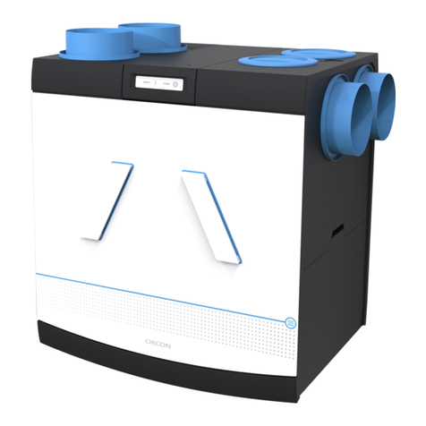
Orcon MVS-15RH User manual

This manual is intended for users and installers of the MVS-15RH mechanical ventilation system. This manual contains
important information about the installation and conguration of the domestic ventilator.
The user manual can be found at the back of this manual.
This manual concerns the following models:
MVS-15RH, MVS-15RHB, MVS-15RHP, MVS-15RHB CO2
Installation manual
MVS-15RH Domestic ventilation

Table of Contents
1. Safety page 2
2. Installing the MVS-15RH domestic ventilator. page 3
3. Electrical installation page 6
4. Adjustment of air volume page 7
5. Conguration en pairing page 10
6. Service and maintenance page 12
7. Technical data page 15
8. Guarantee page 17
9. EC declaration of conformity page 17
10. Installer’s installation report page 18
1. Safety
Read this manual carefully before you mount or use the
device. The following icons are used in this manual.
Indicates the risk that the device will be damaged
if the instructions in this manual are ignored.
Indicates electrical voltage.
1. Only a professional installer may install, connect,
commission and maintain the device unless otherwise
specied in this document;
2. The installation of the device must be performed in
accordance with the general and locally applicable
construction, safety and installation instructions of the
municipality and power company;
3. When performing work on the device, ensure that it
is disconnected from the power supply and cannot
be accidentally reconnected. Bear in mind that after
disconnection from the power supply, the motor will
keep running for approx. 20 seconds.
4. The device is only suitable for a 230 V 50 Hz connection;
5. Modication of the device or the specications listed
in this document is not permitted;
6. The device is only suitable for residential buildings and
not for industrial use, such as swimming pools or saunas;
7. The device cannot be opened without the use of tools,
see Chapter 5;
8. This ventilation device creates negative air pressure in
thehome.Itisimportanttoensurethatnoexhaustgases
from a replace, stove or other combustion devices can
be sucked into the home. It is important that an outside
2

air inlet with sufcient dimensions is always provided for
the (open) combustion device.
9. It must be impossible to touch the fans by hand,
therefore ducting at least 900 mm long must be used.
10. Mount the domestic ventilator out of the reach
of children.
11. After use, place this manual, together with the user part
at the front, back into the device;
2. Installing the MVS-15RH
domestic ventilator
The MVS-15RH consists of a suction plenum with ve
Ø 125/160 mm suction openings and one Ø 125 mm
outlet opening. A volute with inlet ring containing
a motor plate with front cover. The connection openings
are provided with caps which can be easily removed.
The motor and the receiver PCB are mounted on the motor
plate. The humidity sensor is on the receiver PCB .
Steps for installing the MVS-15RH
1. Mount the MVS-15RH device on a wall or ceiling with
sufcient mass (200 kg/m2).
2. Install a silencer at least 1 metre long.
3. Mount the air ducts with as little air resistance as
possible, and free from leakages.
4. Limit the use of exible tubes as much as possible.
5. Cap the unused openings on the suction side with the
supplied caps.
6. Mount the Orcon extraction valvesin the various spaces.
7. Mount the required remote control(s) and CO2sensor(s)
(BRH models only)
8. Connect the MVS-15RH device to the power supply.
9. Pair separately supplied remote control(s) and/or CO2
sensor(s).
If there is more than one remote control, always switch the
device on and off before pairing.
10.. Set the DIP switches of the MVS-15RH device on the
receiver PCB, and adjust the valves. See the chapter
‘Adjustment of air volume’.
3

Installation
The installation must be implemented with as little
resistance as possible in the ducts. Long exible tubes
must be avoided. The caps must not be removed from any
unused inlets. The device is mounted to the wall or ceiling
with the four supplied screws and plugs.
Rear connections
At the rear of the suction plenum, an opening is prepared
for rear connections directly to the wall or the ceiling.
If these connections are used, the gap must be opened
with a Stanley knife. The plenum box can be sealed using
sealing tape (not included).
When using the Ø 160 mm connection under or behind the
unit, cut the adapter/pyramid away with a Stanley knife.
Mounting RF remote control (MVS-15RHB)
The remote control can be opened via the push button (see
gure 6), which is located on the underside. The wall frame
can then either be mounted with the 2 supplied screws and
plugs or be stuck in place. Please note: "UP" is marked on
the mounting frame, when mounting make sure that this is
at the top. Keep enough space free around the underside
so that the push button can be easily reached from below.
It is recommended that the remote control is installed in an
easily accessible place in the living room, kitchen or lavatory.
Never install the remote control near large metal objects,
and keep the remote control out of the reach of children.
4
Fig. 1 MVS-15 Connections
ø125 of ø160
ø125
ø125
ø125 ø125
195
195
344

5
100
442
6
168
159
28 387 28
76 208
13
Fig. 4. Rear view with Ø 160 mm connection
Fig. 5 Base view with Ø 125 mm and Ø 160 mm connection
124
124
159
124
124
87
215
463
124
303
430
Fig. 2 Side view MVS-15
Fig. 3 Top view MVS-15

3. Electrical installation
List of colour codes of power supply wiring
Code Colour
PE Green / Yellow
N Blue
L Brown
M Black (MVS-15RHBP)
H Grey (MVS-15RHBP)
List of DIP switch functions
Options DIP switch
7 8
Table A curve speeds Off -
Table B curve speeds On -
15-minute afterrun humidity sensor - Off
30-minute afterrun humidity sensor - On
6
Fig. 7 Receiver PCB in the device
Fig. 6 Exploded view RF remote control
Upper part
Battery position
Wall frame
Push button to open control
DIP switches
Push button
Red/green LED
M
L
PE
N

7
MVS-15RHP
This model of the device is powered via a cord with Perilex
(P) plug. Please note! An existing 3-position switch no
longer has any function.
Electrical connection domestic ventilator
The MVS-15RH is equipped with a cord and earthed plug for
connection to the power supply. The device can be switched
to four positions, and is equipped with an automatic mode.
The connection of the device must comply with NEN 1010
and any applicable local requirements. Do not insert the
plug into the wall socket until everything is installed.
The device is not suitable for three-phase current.
Supply voltage: 230 V ~50 Hz.
4. Adjustment of air volume
1. Close the windows and doors.
2. Set the extraction valves and (ZR) grilles to their fully
open positions.
3. Set the device to position 2 or 3 (depending on the size
of the home).
5. Open the front cover of the device with a athead
screwdriver.
6. Set the system to the correct total capacity using the
DIP switches.
4. Measure the total air volume in the Orcon extraction
valves and adjust where necessary.
7. Adjust the extraction valves to the correct ow rate for
each space.
8. Complete the installation report (page 18).
On the receiver PCB, a curve can be set with the DIP
switches for each position. The factory settings are curves
1a, 3a and 11a (* in table A).

8
Position Table a curve
speed DIP switch position Air output Pressure Power
consumption
Setting Qv Pf Pe
(Number) 1234567[m3/h] [Pa] [W]
Absent 0 - - - - - - - 45 5 2
*Low 1a Off -----Off 70 10 3
Low 2a On - - - - - Off 85 14 4
*Medium 3a - Off Off Off - - Off 150 46 7
Medium 4a - On Off Off - - Off 171 62 9
Medium 5a - Off On Off - - Off 197 81 12
Medium 6a - On On Off - - Off 222 101 15
Medium 7a - Off Off On - - Off 245 123 20
Medium 8a - On Off On - - Off 270 150 27
Medium 9a - Off On On - - Off 293 175 32
Medium 10a - On On On - - Off 316 205 38
*High 11a - - - - Off Off Off 245 123 20
High 12a - - - - On Off Off 295 177 33
High 13a - - - - Off On Off 318 208 40
High 14a - - - - On On Off 342 241 50
Table A - Table A or B is selected by setting DIP switch 7 to on or off.

9
Position Table b curve
speed DIP switch position Air output Pressure Power
consumption
Setting Qv Pf Pe
(Number) 1234567[m3/h] [Pa] [W]
Absent 0 - - - - - - - 58 3 2
Low 1b Off - - - - - On 83 9 4
Low 2b On - - - - - On 138 14 5
Medium 3b - Off Off - - - On 165 20 6
Medium 4b - On Off - - - On 215 34 10
Medium 5b - Off On - - - On 271 53 16
Medium 6b - On On - - - On 324 77 25
High 7b - - - Off Off Off On 298 65 29
High 8b - - - On Off Off On 353 92 31
High 9b - - - Off On Off On 381 107 38
High 10b - - - On On Off On 405 121 45
High 11b - - - Off Off On On 428 134 52
High 12b - - - On Off On On 452 149 60
High 13b - - - Off On On On 475 163 69
High 14b - - - On On On On 502 184 82
Table B - Table A or B is selected by setting DIP switch 7 to on or off.

10
5. Conguration and pairing
The MVS-15RH is equipped with a receiver PCB on the
motor plate. A separate remote control and/or CO2room
sensor must be paired with the receiver PCB.
Device start up
When the device is connected to the power supply: during
start up, the LED on the device ashes alternately red,
green, red. Then the LED on the device turns green for
3 minutes, during which time the device is in learning
mode and can be linked to a remote control or CO2room
sensor. The MVS-15RH always starts up in automatic mode.
The MVS-15RH is also equipped with a humidity sensor. This
is integrated in the ventilation cabinet. A number of settings
for the functions of this sensor are possible.
DIP switch 8 = OFF / Normal setting.
15-minute overrun*
DIP switch 8 = ON / Extended setting.
30-minute overrun
* Factory setting
Table 3 DIP switch function 7 and 8
Options DIP switch
7 8
Table A curve speeds Off -
Table B curve speeds On -
15-minute afterrun humidity sensor -Off
30-minute afterrun humidity sensor - On
ON
OFF
Fig. 8 DIP switches set to OFF in MVS-15RH

In automatic mode, the MVS-15RH will switch to position
2 when humidity levels increase. The time that the domes-
tic ventilator continues to operate in this mode depends
on the setting of DIP switch 8 and the duration of the
increased levels of humidity.
Pairing remote control(s) to 1 device
The remote control is paired with the MVS-15RHB (CO2) at
the factory. Up to a total of 20 components can be linked
to the device.
Pairing extra remote control(s)
Remove the plug of the device from the power point for
5 seconds. Then reinsert the plug into the power point.
The LED on the device ashes alternately red and green,
after which the LED remains green. The device will be in
learning mode for 3 minutes. During this time, you can pair
remote control(s) by pressing the buttons <1> and <auto>
simultaneously until the LED on the remote control ashes
alternately red, green, red. When the remote control has
been successfully paired, the LED on the device and remote
control will ash green 10 times, and the device will briey
accelerate. The remote control is now ready for use.
Reset remote control
A remote control can be reset by pressing the ‹absent› and
‹timer› buttons simultaneously for 3 seconds. The remote
control indicates that the reset is complete by ashing
orange twice.
Setting the CO2room sensor
The CO2room sensor is paired with the MVS-15RHB CO2
at the factory.
Connect the CO2room sensor to the power supply. During
start up of the CO2room sensor, the orange, green and
blue LEDs light continuously. The LED on the CO2room
sensor ashes red when it is not paired. When the CO2
room sensor is paired, the status LED will turn and stay
green. The CO2room sensor is now ready for use.
Pairing extra CO2room sensor(s)
Remove the plug of the device from the power point for
5 seconds. Then reinsert the plug into the power point.
The LED on the device ashes alternately red and green,
after which the LED remains green. The device remains
in learning mode for 3 minutes. Briey press the control
11

button on the CO2 room sensor once, the red LED ashes.
Then press the button for 7 seconds until the blue LED on
the CO2 room sensor lights up and the status LED ashes
alternately red and green. When the CO2room sensor has
been successfully paired, the green LED on the device and
on the CO2 room sensor will ash 10 times as conrma-
tion, and the device briey accelerates to the high level.
The CO2room sensor is now ready for use. Pairing an
additional CO2room sensor is carried out in the same
way as pairing CO2room sensor number 1.
Unpairing remote control(s) and CO2room sensor(s)
on the device
Remove the cover from the device. Press the push button
on the receiver PCB in the device for 15 seconds until the
LED turns orange. Release the push button. After release,
the LED on the receiver PCB ashes alternately red, green,
red. Any connections with the remote control(s) / CO2
room sensor(s) are now deleted and the factory settings
are loaded. The LED on the receiver PCB remains green
for 3 minutes, during which time the device is in learning
mode and can be linked to components.
Reset CO2room sensor
A CO2room sensor can be reset to factory settings by
pressing the control button for 11 seconds until the LED is
simultaneously red and green (orange). Release the push
button. The CO2room sensor is reset and restarts.
6. Service and maintenance
The following parts of the Orcon ventilation system must be
cleaned regularly:
• Housing - at least every 2 years;
• Fan - at least every 2 years;
• Humidity sensor - at least every 2 years;
• Remote control and CO2room sensor(s)
(see maintenance in the user part);
• Valves and grilles - at least every 2 years;
• Ducts - at least every 4 years.
Maintenance of device
TheMVS-15RHmustbedisconnectedfromthepowersupply
before maintenance is carried out.
12

Removing and installing front cover
Remove the plug from the wall socket. Open the front cover
of the device with a athead screwdriver (g. 9), after which
the front cover can be detached. The wiring, motor and
the receiver PCB with the humidity sensor on the back are
located behind this cover.
Removing and installing motor plate
After the front cover has been removed, the motor plate can
be lifted out with the two handles (arrows g. 10). You can
now easily inspect or clean the motor and humidity sensor.
Avoid imbalances by removing all dirt from the impeller.
Fig. 10 Remove motor plateFig. 9 Open MVS-15 front cover
13

Humidity sensor maintenance
The humidity sensor (g. 11 and g. 12) can be cleaned with
a dry brush.
Removing and installing volute
The volute can be detached from the suction plenum by
gently pulling it out. You can now clean the suction plenum
(g. 13).
Indication LED on the device
The green LED on the receiver PCB indicates the scenario
status of the MVS-15RH. When the LED repeatedly ashes
green once, the MVS-15 is operating normally. If the
LED repeatedly ashes green twice, the MVS-15RH is in
position 2 or 3 due to increased humidity levels. If the LED
repeatedly ashes green three times, the MVS-15RHB CO2
is in position 2 or 3 due to increased CO2levels. If the LED
repeatedly ashes green four times, the MVS-15RHB is in
position 3 due to the timer scenario.
A short orange ash indicates that a signal has been
received from a CO2room sensor or remote control. The red
LED indicates a fault code on the device.
Fig. 11 Motor Plate with motor and humidity
sensor
Fig. 12 Humidity
sensor
Fig. 13 Plenum box with volute and inlet ring
Motor
Humidity
sensor
14

Table 6 List of error codes on device
Device indication red: Function (notication)
Flashing red 1x Motor not running,
check the motor
Flashing red 2x No value from humidity
sensor, check the humidity
sensor
Flashing red 3x RF communication failure
Table 5 List of scenarios shown on device
Device indication green: Function (notication)
Flashing green 1x Normal operation, no hu-
midity, CO2or timer signal.
Flashing green 2x Humidity scenario active
Flashing green 3x CO2scenario active (Exter-
nal CO2room sensor).
Flashing green 4x Timer scenario active
7. Technical data
MVS-15RH
Supply voltage: 200-240 V single phase 50 Hz
Current consumption 0.8 A
Max. power consumption
consumption 85 W
Min.ambienttemperature -10 °C
Max. ambient
temperature +40 °C
Humidity
(continual)
95%(motor) non-condensing
85%(electronics),
non-condensing
Weight 4.4 Kg
Height 389 mm
Width 449 mm
Depth 303 mm
Height with connections 467 mm
15

RF CO2sensor
Supply voltage: 230 V
Frequency 50 Hz
Max. power consumption 4 W
Temperature class T40
Dimensions 92 x 92 x 23 mm
Weight 125 g
RF frequency 868.3 MHz
Min./max. ambient
temperature 0-40 °C
RH level 0-90%non-condensing
Protection class IP30
Functional range 400 - 2000 ppm
RF remote control
Supply voltage: Powered by 3 V battery
Temperature class T40
Dimensions 83 x 80 x 28 mm
Temperature class T40
Dimensions 83 x 80 x 28 mm
Weight 125 g
RF frequency 868.3 MHz
Min./max. ambient
temperature 0-40 °C
RH level 0-90%non-condensing
Protection class IP30
16

8. Guarantee
Orcon BV guarantees the fan for two years as standard.
The guarantee period starts on the production date.
The guarantee is void if:
• The system is not installed in accordance with applicable
regulations;
• The defects have been caused by incorrect connection,
improper use or dirt in the fan or accessories;
• Changes have been made to the wiring;
• Repairs have been carried out by third parties.
On-site disassembly and assembly charges are not covered
by the guarantee. If a defect occurs within the guarantee
period, it must be reported to the installer. Orcon BV
reserves the right to change the structure and/or
conguration of its products at any time without being
obliged to change previously supplied products. The data
in this manual concerns the most recent information.
For extended guarantee, see Chapter 5 in the user part.
9. EC declaration of conformity
Orcon BV
Landjuweel 25
3905 PE Veenendaal, NL
Tel.: +31 (0)318 54 47 00
Fax.: +31 (0)318 54 47 06
Device description:
MVS-15RH domestic ventilator
Meets directives:
Machinery Directive (2006/42/EC),
Low Voltage Directive (2006/95/EC),
EMC Directive (2004/108/EC),
RoHS directive (2002/95/EC),
R&TTE Directive (1999/5/EC).
Veenendaal, NL
M. Voorhoeve, General Manager
17
!

* Circle applicable setting
DIP switch Setting
1on/off
2on/off
3on/off
4on/off
5on/off
6on/off
7on/off
8on/off
18
Installation report
Date:
Address:
Town or City:
Type of project:
Type of property:
Client:
Installed by:
Measured by:
Type of device:
Serial number:
10. Installer’s installation report

Space / valve Position on device Required [m3/h] Measured m3/h Setting MKL valve (1-6)
Kitchen
Lavatory
Bathroom
19

1
Table of Contents
1. General introduction page 1
2. How the ventilation system works page 2
3. Operating the system page 2
4. Maintenance page 6
5. Guarantee page 8
1. General introduction
Orcon exceptional indoor climate?
Our objective is to offer occupants an exceptional indoor
climate which is as comfortable and healthy as possible,
where people can feel at ease and function at their best.
With this aim, we have grown into a leading supplier of
ventilation systems for residential and nonresidential
buildings.
The importance of good ventilation
MVS stands for Mechanical Ventilation System
The system can operate fully automatically, and it saves
energy and money. As an additional benet, it is good for
your health! You need approximately 25 m3of fresh air
per hour, so good ventilation is simply a must. Without
good ventilation, a home becomes damp and musty. This
attracts mould and house dust mites. Poor ventilation
means damp patches in walls and ceilings are a certainty,
as well as health problems such as headaches, allergies
and respiratory irritations.
We are, of course, outlining an extreme situation, but there
are excellent reasons why good ventilation systems are
compulsory in new houses. You and your home need fresh
air! Opening a window for a bit is not enough. The moment
you close the window, the fresh air disappears.
Houses are increasingly well insulated. However you look
at it, this is a positive development, because it saves a lot
of energy and money. Unfortunately, good insulation does
reduce the refreshment of air in your home, because in an
airtight house air cannot from pass from the outside to
the inside, or vice versa. And that is not a good develop-
ment at all, because you and your home need fresh air.
There is a lot of moisture in a house, and its occupants
also produce moisture. Without proper ventilation, humi-
dity and stale air remain contained, with bacteria and
Table of contents
Other Orcon Fan manuals
Popular Fan manuals by other brands

Johnson Controls
Johnson Controls DSH Series Installation, operation & maintenance instructions

Adler Europe
Adler Europe AD 7323 user manual

ECG
ECG TV 3030 Heat R instruction manual

ClimateMaster
ClimateMaster OB Series installation instructions

Casablanca
Casablanca 4TS26IIRB owner's manual

Electric Co
Electric Co AV06 instruction manual