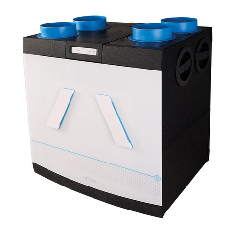
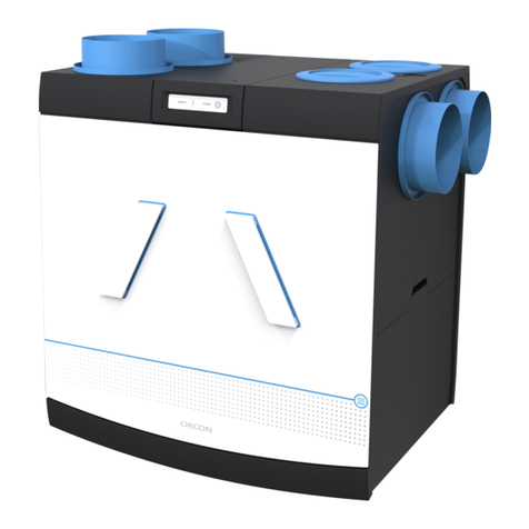
Orcon HRC-EcoSmart User manual

User Guide
HRC-EcoSmart / HRC-SmartComfort
Balanced ventilation with heat recovery &
zone control
This manual is intended for the users of the HRC-EcoSmart and HRC-
SmartComfort balanced ventilation system. The manual contains important
information about the operation and maintenance of the ventilation unit with
heat recovery and zone control.
These instructions belong to the versions:
HRC-425-EcoSmart
HRC-425-SmartComfort
HRC-570-EcoSmart
HRC-570-SmartComfort

2
Table of contents
4
5
8
9
18
22
1. Precautions and safety instructions
2. General operation balance ventilation system
3. Product informatie
4. Controlling the device
5. Maintenance
6. Faults
7. Certification and warranty
27

3
Why ventilate?
Orcon: exceptional indoor climate
Our goal is to provide residents with the most comfortable and healthy (extraordinary)
indoor climate possible, in which they feel comfortable and can function optimally.
The importance of good ventilation
Houses are increasingly well insulated. This is a good development, because it
saves a lot of energy and money. However, good insulation does reduce the
exchange of air in your home, because in an airtight home, air cannot flow from the
outside to the inside, or vice versa. And that is not a good thing, because you and
your home need fresh air.
Simply opening a window is not enough; by the time you close it, the fresh air has
already disappeared. You need about 25 m³ of fresh air per hour, so good
ventilation is a necessity. Without good ventilation it becomes damp and musty in
the house, resulting in bacteria, mould and health complaints such as headaches,
allergies and respiratory irritations. Moreover, heating this moist air costs more
energy than heating dry air.
Of course, this is an extreme situation, but a good ventilation system is
mandatory in new houses for a reason. This balanced ventilation system can
operate fully automatically and saves energy. But more importantly, it also
benefits your health!

4
1. Precautions and safety instructions
1.1.Safety regulations
• Installation, commissioning and maintenance must be carried out by a
recognised installer, unless otherwise indicated. An unauthorised installer may
cause personal injury or damage to the functioning of the ventilation system;
• After installation, all parts that could cause personal injury are safely inside the
housing. Do not open the housing;
• Always follow the safety regulations, warnings, notes and instructions
in this manual. Non-observance of
Safety instructions, warnings, notes and instructions may lead to personal injury
or damage to the device;
• It is not permitted to modify the unit or its specifications in this document. A
modification may cause personal injury or damage to the functioning of the
ventilation system;
• Do not unplug the appliance unless instructed to do so in the operating
instructions.
• Replace the filters (at least) every six months. This keeps the indoor air
healthy and comfortable and protects the unit from dirt;
• Always leave the user manual with the device.
1.2.Scope
The unit is only suitable for domestic use and not for industrial use, swimming pools
and/or saunas. The air flow rate of the unit must match the ventilation requirements of
the home.
Note: It is not permitted to connect a motorised extractor hood or a
tumble dryer to the system.

5
2. General operation of balanced
ventilation system with zone control
In order to create a healthy living environment in your home, good ventilation is
required. Your house is therefore equipped with an Orcon mechanical supply and
exhaust ventilation system. This system consists of a centrally installed balanced
ventilation unit
(HRC-EcoSmart/SmartComfort) with zone control, a duct system with supply
and exhaust valves in the various rooms and can be combined with a
position switch, an RF remote control and/or CO2 room sensor(s).
1. A centrally located
HRC-EcoSmart/SmartComfort domestic
ventilation system with humidity sensor &
zone control
2. Zone control valves, placed in
the inlet.
3. Remote control 15RF or
HRC Display built-in
15RF
4. CO2 sensor 15RF
5. Silencers (minimum 1m) for a
very quiet installation
6. Air distribution system for the
supply and extraction of
contaminated air to and from
the unit
7. Roof duct
8. Wall outlet
Overview ventilation system HRC-EcoSmart/SmartComfort
In balance
The HRC-EcoSmart/SmartComfort is equipped with two fans: an inlet fan. The
exhaust fan ensures that warm, moist and contaminated air is removed from the house.
The supply fan ensures a sufficient supply of clean outside air.
Heat exchange
The supply air, which in winter will be rather cold due to the cold outside air, is first
heated in the HRC by means of the heat extracted from the warm return air from the
house. Conversely, in the summer months, the warm supply air from outside will be
cooled by the cooler return air from the house.
7
2
8
1
5
6
4 4
4
3

6
The built-in heat exchanger ensures that up to 99% of the heat is transferred, which
means that hardly any valuable heat is lost and the inlet temperature is at a
comfortable level.
Zone control
With the zone control on the device, ventilation takes place in the room where
ventilation is required. Smart sensors, placed in the living & sleeping areas,
determine where ventilation is needed. During the night, the ventilation need is
reduced in the living room and increased in the bedrooms. In this case, the device
will ensure that there is reduced ventilation in the living room. And the air supply in
the bedroom is kept optimal.
This makes the HRC-EcoSmart/Comfort very energy-efficient as it only ventilates
the room where it is needed. As a result, the ventilation system is also whisper-
quiet.
Bypass
In the summer situation, when heat recovery is not desired, the air is not led
through, but past the heat exchanger via a bypass valve. This makes it possible to
ventilate the house with relatively cool outside air during the night in the summer,
so that the house is relatively cool again in the morning. The bypass automatically
works at the best moment to achieve maximum comfort.
Frost protection
When the outside temperature in winter is around freezing point, it is possible that
ice will form in the exchanger. The result is that cold air is blown into your home. To
prevent this, the HRC will heat the exchanger in time using the warm indoor air
from your home. To do this, the unit will temporarily turn up the extract air fan at a
higher speed than the supply air fan.
The HRC-MaxComfort has a built-in pre-heater that switches on automatically to
prevent the heat exchanger from freezing.
Moisture sensor
Your HRC is fitted with a humidity sensor as standard, which measures the
moisture content in the extract air from the kitchen, bathroom and toilet. If the
built-in humidity sensor
If the humidity rises, for example while cooking or taking a shower, the unit will
automatically switch to a higher setting. 15 minutes after showering or cooking, the unit
will switch back to the lower setting.

7
Filters
The HRC is equipped with two filters. A filter for filtering the supply air and a filter
for filtering the return air. The supply filter ensures that only clean air enters your
home and that dust, soot and insects remain outside.
Optionally, you can also use a pollen filter for the supply filter. The exhaust filter
ensures that the air from your home is also filtered, so that the contamination of the
exchanger remains minimal.
For an optimal indoor climate, we recommend cleaning the filters every 3 months
and replacing them once every 6 months. The HRC is equipped with a filter
indicator, which indicates when the filters need to be cleaned. For more
information about cleaning your filters, see chapter 5.
Attention: Ensure sufficient air supply. Never tape valves together or
close them!
Please contact your installer if you have any questions or if you want to
order new filters. Filters can also be ordered directly in the Orcon
webshop: www.orcon.nl/winkel

8
3. Product Information
3.1.Device types
The Orcon HRC is equipped with an intelligent electronic control circuit, which
ensures optimum operation and protection under all conditions.
The table below lists the different versions.
1 In accordance with Article 3.29 Paragraph 5 of the 2012 Building Decree
3.2.Optional accessories
The unit can be expanded with the Orcon articles listed in the table below.
HRC-425
EcoSmart
(300)
HRC-425
SmartComfo
rt (300)
HRC-570
EcoSmart
(400)
HRC-570
SmartComfo
rt (400)
Article no.
22001090
22001095
22001100
22001105
Air flow
rate [m³/
h]
at max. 200 Pa
300
300
400
400
Capacit
y in
accorda
nce
with 70
% rule1
425
425
570
570
Channel
connection
[mm]
4 x
ø160
2 x
ø160
Zone
valve
4 x
ø160
2 x
ø160
Zone
valve
4 x
ø180
2 x
ø160
Zone
valve
4 x
ø180
2 x
ø160
Zone
valve
For heater
no
yes
no
yes
Filter class
2x coarse
65%
supply:
2x coarse
65%
supply:
(ISO16890)
ePM1 70%
ePM1 70%
drain:
drain:
coarse 65%
coarse 65%
Article
Article number
Remote control 15RF
21800000

9
CO2 room sensor 15RF
21800040
CO2 sensor 15RF
21800050
CO2 control sensor 15RF
21800045
HRC built-in display 15RF
21800060

10
4. Operating the appliance
The HRC can be operated with various accessories. This chapter describes how to
use the optional controls. For a detailed description, please refer to the operating
instructions of the respective control.
4.1.Operation with 3 position switch
If your unit has a perilex connection and a 3 position switch, the ventilation positions
from the table below can be set. If several switches or controls have been applied in
your home, the most recently selected ventilation setting will always be leading.
4.2.Operation with Remote Control 15RF
The balance fan can be operated by wireless remote control
(15 RF). The remote control has 6 buttons, the functions of which are explained in the
table below.
Position
1
Low
For use during long absences
Position
2
Middle
For daily use in normal housekeeping
Position
3
High
For use during cooking, showering
or celebrations
Button
Operation
Function
1x short
Absence mode
1
1x short
Position 1 (low position)
2
1x short
Position 2 (centre position)
3
1x short
Position 3 (high position)
1x short
Position 3 (timer position) temporary 15 minutes
2x short
Mode 3 (timer mode) temporary 30 minutes
3x short
Mode 3 (timer mode) temporary 60 minutes
car
1x short
Automatic mode
Explanation of ventilation modes
Remote control buttons explained

11

12
Absence mode
In the absence mode, the unit runs in the minimum ventilation mode.
Timer mode
In timer mode, the unit runs for a desired time in position high, after the time has
elapsed the unit returns to the last selected position. The timer can be cancelled by
selecting another (desired) setting.
Automatic mode
In auto mode, the unit runs based on the moisture content in your home.
The moisture sensor is integrated as standard in the HRC and measures the moisture
content in the extract air from the kitchen, bathroom and toilet. If the humidity sensor
detects that the humidity level is rising, the device will automatically switch to a higher
setting. 15 minutes after showering or cooking, the device will switch back to its
previous setting. If your appliance has been upgraded with a CO2 room sensor, the
automatic mode works on the basis of the CO2 content. The system can be expanded
with additional controls/CO2 room sensors (up to a maximum of 20 controls per
appliance).
4.3.Control with the CO2 room sensor
This sensor measures the CO2 concentration (air quality) in the room and automatically
increases ventilation when necessary. This prevents unnecessary ventilation, which
benefits the energy efficiency of the device.
Indication and operation CO2 room sensor
By touching the operating button once, the status is shown by the LEDs. After 30
seconds the LEDs switch off automatically to avoid disturbing a dark room. If the
operating button is pressed again, the sensor switches to a different mode. The
mode change is indicated by the green or blue LED on the top right of the CO2 room
sensor lighting up.
The CO2 room sensor has the following two modes:
• Energy-saving mode
When the CO2 room sensor is in this mode, the unit will ventilate according to
the standard requirement. This saves on energy costs, as ventilation is only
provided when it is actually needed.
• Extraordinary mode
When in this mode, the CO2 room sensor will keep the air quality at a high
level. This will increase ventilation, removing the dirty air particles from the
house and bringing in fresh air from outside.

13
4.4.Control with the CO2 built-in sensor
This built-in sensor measures the CO2 concentration (air quality) in the room and
automatically increases ventilation when necessary. This prevents unnecessary
ventilation, which benefits the energy efficiency of the device.
Indication and operation with the CO2 built-in sensor
By pressing the operating button once, the status is shown by the LEDs. After 30
seconds the LEDs switch off automatically to avoid disturbing a dark room. If the
operating button is pressed again, the sensor switches to a different mode. The
mode change can be recognised by the LED's lighting up.
Status LED
LED modes Control bu3on
CO2 sensor
Status
Led
Function
Absence stand
Unit runs in lowest possible position until another
function is activated (12 hours)
1
Position 1 (temporary low position)
2
Position 2 (temporary intermediate position)
3
Position 3 (temporary high position)

14
Energy-saving
Auto mode
Automatic regulation on the basis of CO2 <1150 PPM
Outstandingly
Good Auto Mode
Automatic control based on CO2 <950 PPM

15
The CO2 built-in sensor has the following modes:
•Absence and positions 1, 2 and 3
When the CO2 recessed sensor is in the off position, the unit will ventilate a
minimum amount. Only the Status LED lights up and goes out after 30
seconds. This mode remains active for 12 hours.
Mode 1 (low), 2 (medium) and 3 (high) are temporary modes. If modes 1 (low) and
3 (high) are selected, the system will return to automatic mode after 60 minutes
and the LEDs will remain on during this time. For setting
2 (middle) is 13 hours, this setting can be chosen as a night setting in situations
where not every bedroom is equipped with a CO2 sensor.
•Energy-saving mode
When the CO2 built-in control sensor is in this mode, the fan will ventilate according
to the standard requirement. This saves on energy costs, as ventilation is only
provided when it is really needed.
•Extraordinary mode
When it is in this mode, the CO2 built-in sensor keeps the air quality level at a very
good level. As a result, more ventilation takes place, which means that the dirty air
particles are removed from the house more quickly. The clean outside air is brought
inside.

16
4.5.Operation with CO2 control sensor
The HRC can also be operated with the CO2 control sensor. This is a CO2 sensor with
integrated control. By touching the control button once, the LEDs indicate the
status. After 30 seconds the LEDs will automatically switch off again, in order not to
disturb a dark living room. If the control button is pressed again after being pressed
once, the CO2 control sensor switches to a different mode.
CO2 Plus system
It is possible to place a CO2 room sensor, flush-mounted sensor and/or flush-
mounted display or control sensor in each occupied room. This can be extended
to up to 15 CO2
Room sensors (and 5 remote controls). These sensors communicate wirelessly with
the HRC-EcoSmart/SmartComfort ventilation unit.
Absence mode
Appliance running at lowest possible setting (12
hours)
Automatic position
Automatic control based on humidity and CO2
1
Position 1
Tem po ra ry low position (60 min)
2
Position 2
Temporary middle position (13 hours)
3
Position 3
Temporary high mode (60 min)
Status LED (red/green)
LED energy-saving mode (green)
LED Outdoor
Just Good
Mode (blue)
Control button
Wall frame
CO2 control sensor

17
When the remote control is set to automatic mode, the unit responds to the highest
CO2 level (air quality in a residential area) measured by the CO2 room sensors. This
provides fully automatic control, ensuring an exceptional indoor climate for the
occupant at all times. You can always choose a different speed with the remote
control. The automatic mode will then lapse. After any power outage, the fan will
start in the automatic mode.

18
4.6.HRC Display Built-in 15RF
The HRC can be operated and read with the HRC Display built-in 15RF. The display
has control buttons with which the appliance can be operated. It is also possible to
use the display to read out the status of the appliance and to change various settings.
Indication and operation Built-in display
By briefly touching one of the buttons, the display lights up and shows the current
status of the connected HRC. Subsequently, the buttons below can be used to change
or read out the HRC settings.
A. OK button: Select menu
B. UP button: Increase fan speed or move
forward in a menu.
C. DOWN button: Decrease fan speed or
go back in a menu.
D. MENU button: Scroll through
available settings.
E. BACK button: To return to the
standard screen.
Automatic
position
Automatic ventilation according to humidity and/or CO2
demand
Position 1
Manual Position 1
(low position, active until selection change)
Position 2
Manual Position 2
(centre position, active until selection mode change)
Position 3
Manual Position 3
(high position, active until selection mode change)
Absence stand
Appliance running in lowest possible position
High
mode/
Party
mode
Unit ventilates the maximum unit capacity
A
B
E
C
D
Built-in display

19
Tem po ra ry stand
Appliance runs temporarily in position 3 (60 min)

20
Changing fan settings
In the standard screen, the fan speed can be changed using the UP and DOWN
buttons.
Read out device settings
Settings of the HRC can be read by pressing the Menu button until the following icon
appears in the display. By touching the UP or DOWN button the following
settings can be read out. Press the OK button to select the reading menu.
No.
Description
No.
Description
1
Software version
10
Bypass position
4
RV value in dwelling (%)
11
Exhaust fan speed (%)
5
RH value supply air (%)
12
Supply air fan speed (%)
6
Exhaust air temperature to
the outside (°C)
13
Remaining after running time
(moisture scenario) (min.)
7
Supply air temperature to the
dwelling (°C)
14
Pre-heater control
(MaxComfort) (%)
8
Tem pe ra ture ou t of dwe llin g
(°C)
16
Current supply flow rate (m3/h)
9
Outdoor temperature (°C)
17
Current discharge flow rate
(m3/h)
Built-in display
This manual suits for next models
5
Table of contents
Other Orcon Fan manuals