Orenco Systems®• 800-348-9843 • +1 541-459-4449 • www.orenco.comNIM-EPS-1
Rev. 6 © 10/21
Page 8
Biotube ProPak and LOS Pump Package Installation Manual
Step 8. Test Float Switches and Control Panel
• If you’re using a generator for pump operation, contact your dealer to
make sure it can supply sufficient starting amperage to the pump(s).
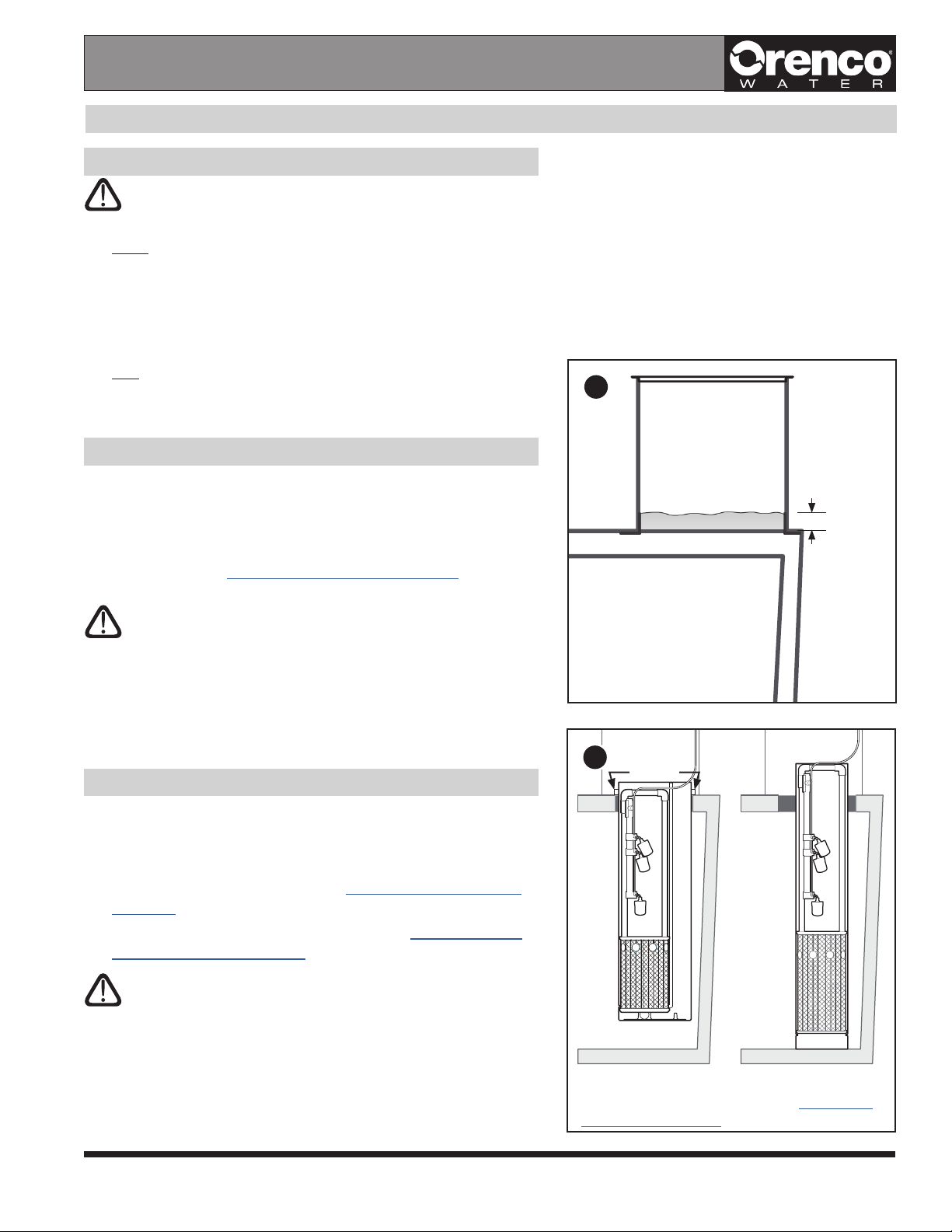
• Make sure there’s enough liquid in the tank to safely run the pump –
at least 4in (100mm) above the bottom float switch – and make sure
the pump doesn’t run dry during testing.
Step 8a: Make sure that the control panel has power and that the float
switch assembly has been removed from the tank.
Step 8b: Perform an operational test of the float switches in the float switch
assembly, based on the applicable configuration found in this section.
• If the panel doesn’t perform as it’s supposed to, check the wiring
diagram for proper wiring. Contact your distributor for assistance.
Demand-Dose: “Y,G” or “Y,G,W” Float Switch Assemblies
(MVP-S, S1, or S1RO Control Panels)
• Place the “Pump On/Off” and the “Redundant Off/Low-Level Alarm” (if
included) switches in the “up” position.
– The pump begins to run.
• Place the “High-Level Alarm” switch in the “up” position.
– The audible alarm sounds; the panel door alarm light turns on.
• Place the “High-Level Alarm” switch in the “down” position.
– The audible alarm goes silent; the panel door alarm light turns off.
• Place the “Pump On/Off” switch in the “down” position.
– The pump stops running.
• Place the “Redundant Off/Low-Level Alarm” switch (if included) in the
“down” position.
– The audible alarm sounds; the panel door alarm light turns on.
(On MVP panels, the panel door alarm light begins to blink.)
Demand-Dose: “Y,B,R” or “Y,B,R,W” Float Switch Assemblies
(MVP-S, S1, or S1RO Control Panels)
• Place the “Pump Off” and the “Redundant Off/Low-Level Alarm” (if
included) switches in the “up” position.
• Place the “Pump On” switch in the “up” position.
– The pump begins to run.
• Place the “High-Level Alarm” switch in the “up” position.
– The audible alarm sounds; the panel door alarm light turns on.
• Place the “High-Level Alarm” switch in the “down” position.
– The audible alarm goes silent; the panel door alarm light turns off.
• Place the “Pump On” switch in the “down” position.
– The pump continues to run.
• Place the “Pump Off” switch in the “down” position.
– The pump stops running.
• Place the “Redundant Off/Low-Level Alarm” switch (if included) in the
“down” position.
– The audible alarm sounds; the panel door alarm light turns on.
(On MVP panels, the panel door alarm light begins to blink.)
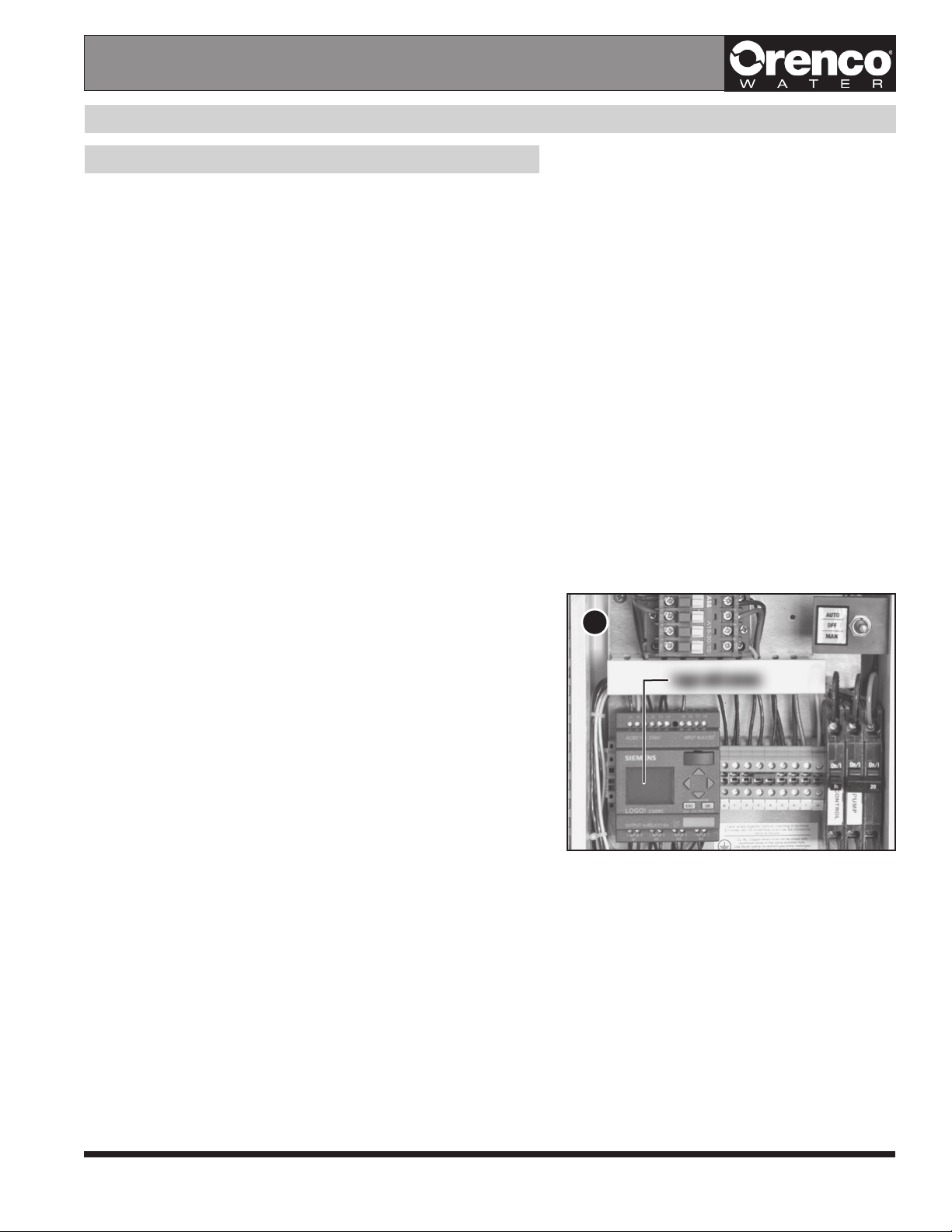
8
Lift and lower float switches to test switches and controlLift and lower float switches to test switches and control
panel functions (three-float configuration shown).panel functions (three-float configuration shown).
Installation Steps