10
AIM-OM-ATX-3, Rev. 2.1, 05/15 • Copyright Orenco Systems®, Inc. Property of Orenco Systems®, Inc. Do not reproduce or distribute without written authorization from Orenco: 800-348-9843.
AdvanTex® O&MMANUAL
COMMERCIAL TREATMENT SYSTEMS
e. When the floats and filter cartridge are out of the tank, verify the
handles are long enough for easy access. If they are not, adjust
them to the necessary length.
f. Reinstall the cartridge in the pump vault. Leave the float assembly
out of the tank or basin for use during pump run testing.
7. Effluent pump: Verify the pump is easy to remove for service and
maintenance and that the pump flow rate and voltage are correct.
The ability to easily remove the pump is essential and depends upon
careful installation in accordance with the instructions provided in
Appendix B. Set components on a plastic tarp or plastic sheeting
when they are out of the tank.
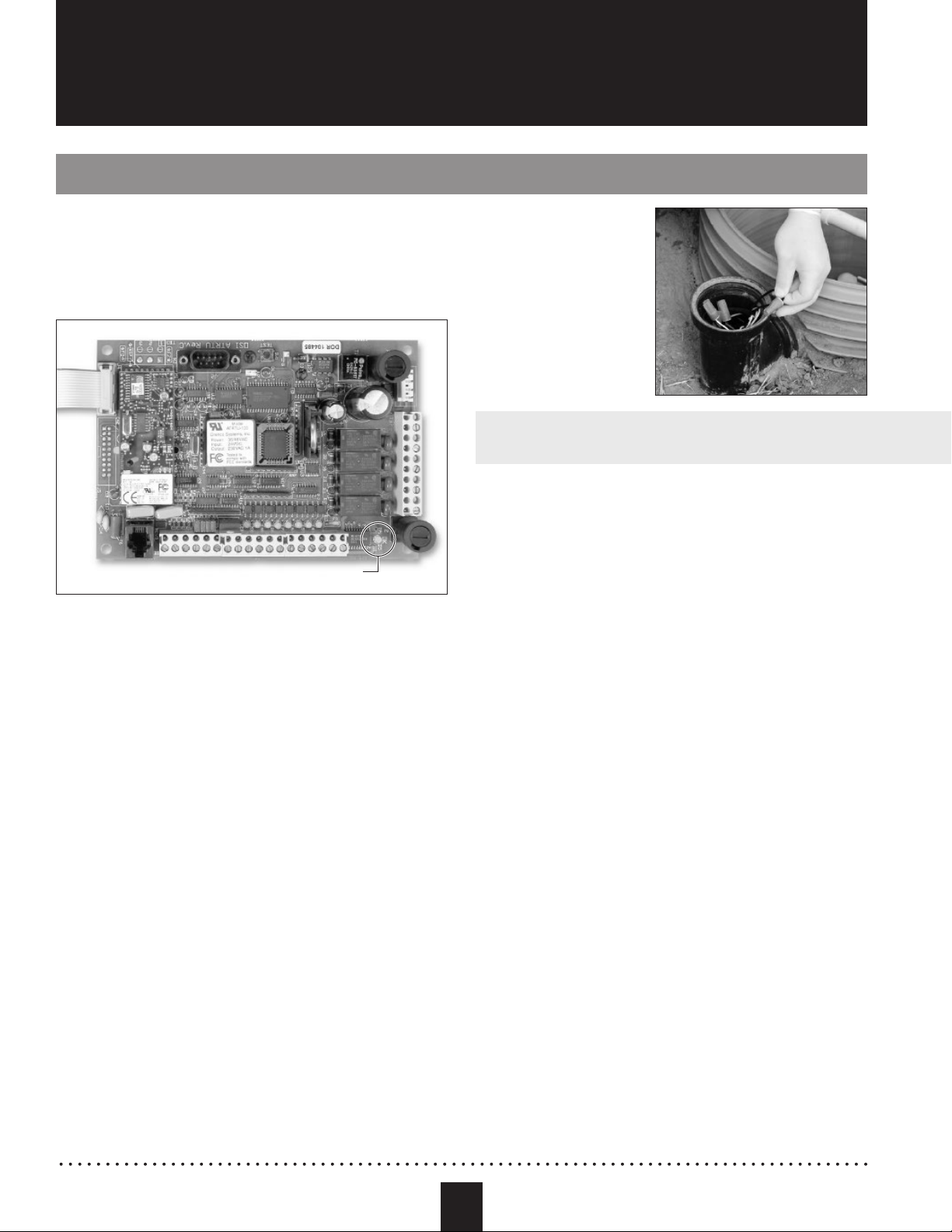
a. Switch the pump breaker(s)
in the control panel to the
“OFF” position.
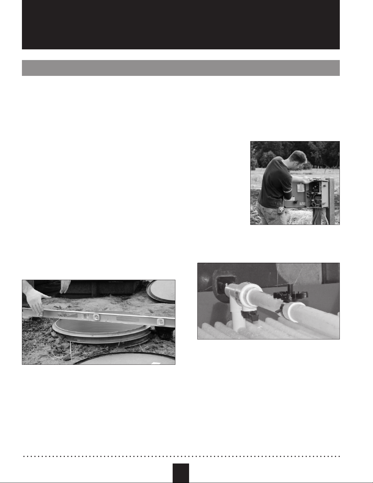
b. Verify the ball valve and
cam-lock fitting or union on
the discharge assembly is
within 24 inches (610 mm)
of the top of the riser.
c. Close the ball valve on
the discharge assembly if there is one and disconnect the
discharge assembly at the union or cam-lock fitting.
d. Verify there is enough slack in the pump cord for easy removal.
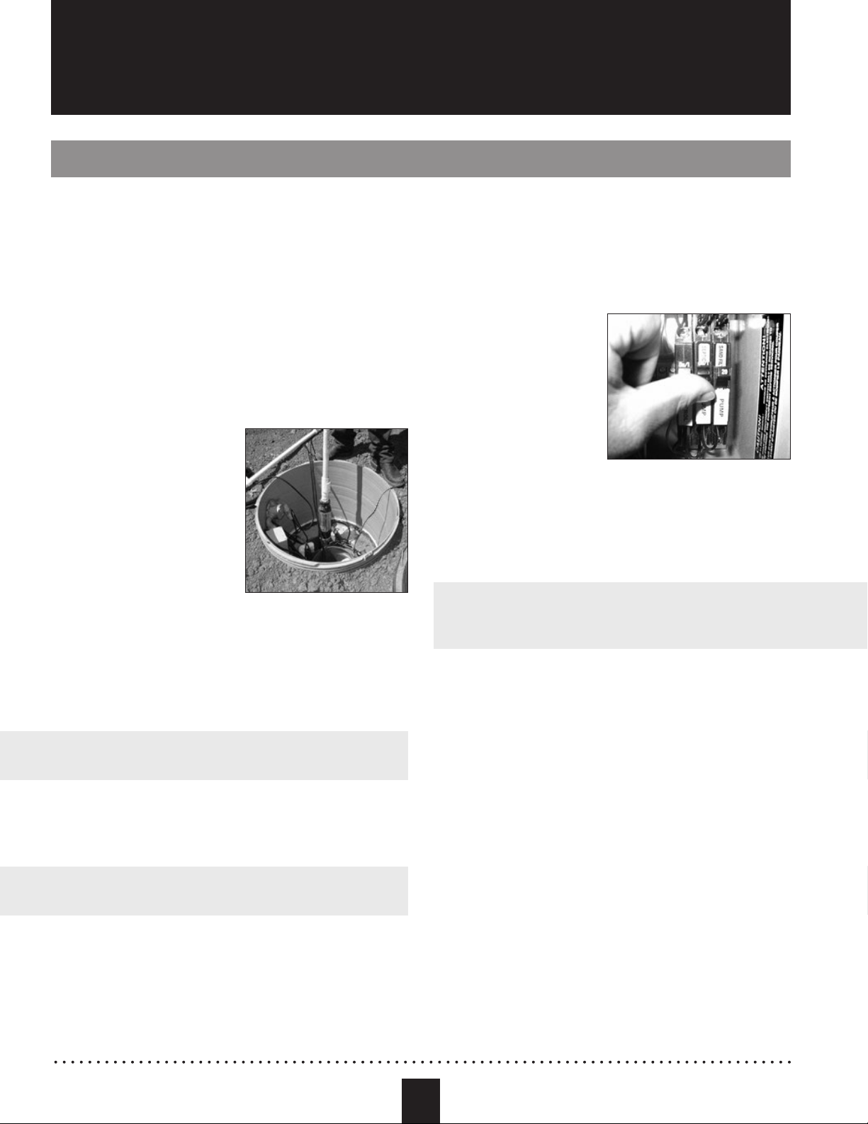
e. Pull the pump out of the vault by the discharge assembly and
remove the pump from the tank.
WARNING: Lifting or lowering the pump by the cord can
damage the pump and cord.
f. Check the voltage and phase values on the pump nameplate.
Write them down in the start-up report. If there are pump motor
stickers on the inside of the control panel door, check to see if
they match the pump nameplate.
WARNING: If the pump does not match the panel voltage and
phase requirements, do not turn on the pump breakers.
g. Reinstall the pump if the pump matches the panel voltage and
phase requirements.
h. Reconnect the discharge assembly at the union or cam-lock fitting
and open the discharge assembly ball valve.
i. Switch the pump breaker(s) in the control panel to the “ON” position
when finished.
Inspection Points – Pumps
When the panel has been inspected and powered up, the float inputs
have been tested, and all pump voltage and phase information has been
verified, the pump(s) can be powered up and tested.
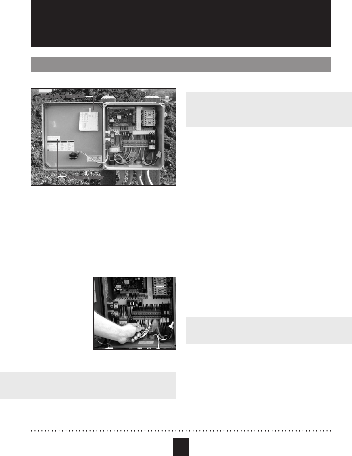
1. Manual pump operation:
a. Switch the pump
breaker(s) in the control
panel to the “ON” position.
b. Measure the static
voltage of the pump(s)
and enter the value(s) on
the start-up checklist.
c. Toggle the pump
“AUTO-OFF-MAN” switch to “MAN.” The motor contactor will
visibly and audibly engage at this point. If the motor contactor
does not engage, check for an “RO” alarm condition. If there is
no alarm condition, refer to the wiring diagram and verify the
connections on the control circuit were properly terminated.
WARNING: There is no motor protection in TCOM panels and
panels without “RO” alarms. Before running a pump, always verify
that there is sufficient liquid in the tank or basin.
NOTE: Refer to the “General Operating Instructions” section of the
VCOM control panel documents to perform the “Manual Test” if
you are starting up a pump controlled by a VCOM panel.
d. Verify pump motor operation by checking the discharge plumbing
assembly for vibration.
– No vibration in the discharge plumbing assembly indicates a
pump wiring issue. Check the pump voltage and pump wiring
terminations in the panel and in the splice box. Wires may be
incorrectly terminated or wire insulation may be causing faulty
contact between the wire and terminal lug.
– Vibration in the discharge plumbing assembly with low or no
flow from the pump indicates closed valves or line breakages.
On duplex pumping systems with two discharge plumbing
assemblies connected together to a single line, verify that there
are check valves on both pumps and that they are operating
correctly. On three-phase systems, verify L1, L2 and L3 are
wired correctly. A quick way to identify if the pump is wired
correctly is to watch for clockwise torsion in the discharge
plumbing assembly when the pump is first turned on.
Inspection Points (continued)