Silca Ilco Orion SMARTY 2000 User manual

®
D430568XA
vers.
3.0
Operating manual
SMARTY 2000

© 2002 SILCA S.p.A - Vittorio Veneto
This manual has been drawn up by ILCO ORION.
All rights reserved. No part of this publication may be reproduced or used in any form or by any means (photocopying, microfilm
or other) without the written permission of ILCO ORION.
Edition: june 2006
Printed in Vittorio Veneto
by ILCO ORION.
via Podgora, 20 (Z.I.)
31029 VITTORIO VENETO (TV) - Italy

INDEX
GUIDE TO THE MANUAL ......................................................................................................5
GENERAL INTRODUCTION.................................................................................................. S
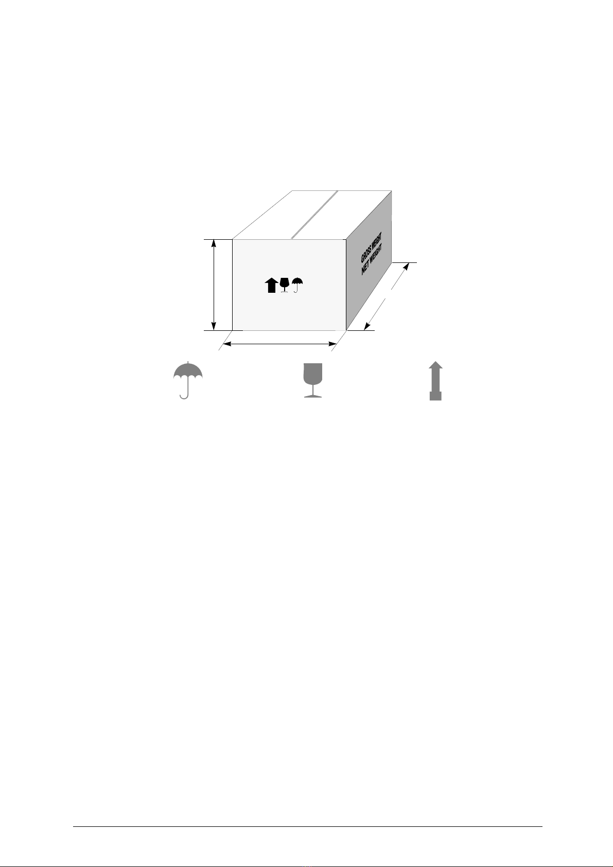
1 TRANSPORT 7
1.1 Packing ..........................................................................................................7
1.2 Transport .......................................................................................................7
1.3 Unpacking ......................................................................................................7
1.4 Handling the machine ....................................................................................7
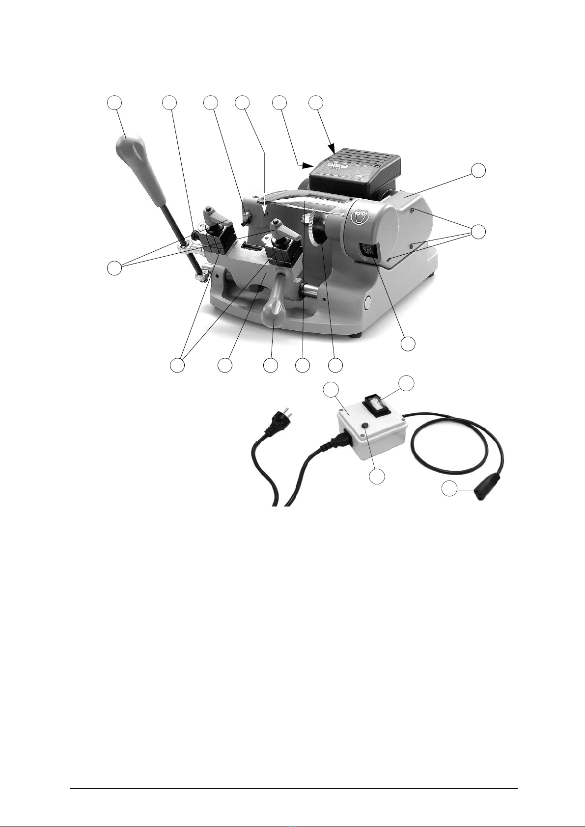
2 MAIN WORKING PARTS ................................................................................8
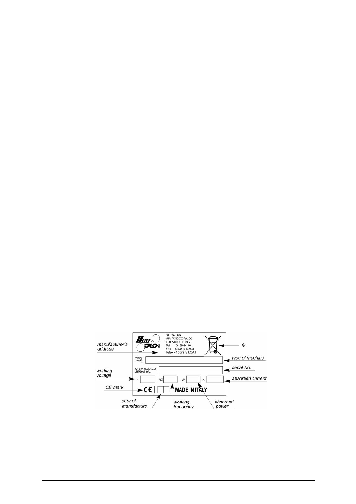
3 MACHINE DESCRIPTION ...............................................................................9
3.1 Technical Data .............................................................................................10
3.2 Electrical system ..........................................................................................11
4 ACCESSORIES PROVIDED .........................................................................12
5 MACHINE INSTALLATION AND PREPARATION .......................................13
5.1 Checking for damage ...................................................................................13
5.2 Environmental conditions .............................................................................13
5.3 Positioning ...................................................................................................13
5.4 Description of work station ...........................................................................13
5.5 Graphics ......................................................................................................14
5.6 Separate parts .............................................................................................14
5.7 Removing the blocks ...................................................................................14
5.8 Connection to the mains ..............................................................................14
6 REGULATION AND USE OF THE MACHINE ..............................................15
6.1 Checking and setting ...................................................................................15
6.2 Calibration ....................................................................................................15
7 Key cutting ....................................................................................................16
7.1 Key cutting ...................................................................................................16
7.2 Using the accessories ..................................................................................17
8 MAINTENANCE .............................................................................................19
8.1 Replacing the cutting tool ............................................................................19
8.2 Replacing the brush .....................................................................................19
8.3 Replacing the belt ........................................................................................20
8.4 Replacing the tracer point ............................................................................20
8.5 Replacing the fuses .....................................................................................20
9 DISPOSING OF MACHINE ...........................................................................21
10 AFTER-SALES SERVICE .............................................................................22
10.1 How to request service ................................................................................22


Operating manual - English SMARTY 2000
5
GUIDE TO THE MANUAL
This manual has been produced to serve as a guide for users of the SMARTY 2000 key-cutting
machine. Read it carefully; it is essential if you wish to operate your machine safely and efficiently.
Consultation
The contents of the manual are divided into sections relating to:
- Transport and handling
- Description of machine and safety devices
- Proper use of machine
- Maintenance
Technical terms
Common technical terms are used in this manual. To assist those with little experience of key cutting,
below is an illustration of the terms used for the different parts of keys:
Fig. 1
1) Head
2) Rim
3) Stop
4) Stem
5) Tip
6) Back
7) Cuts
2
1
5
7
3
6
4

SMARTY 2000 Operating manual - English
6
GENERAL INTRODUCTIONS
The SMARTY 2000 key-cutting machine has been designed according to the specifications of the
Machine Directives. From the design stage risks for the operator have been eliminated in all areas:
transport, key-cutting, regulation and maintenance.
A special adhesive label is attached to the machine warning the operator to use goggles during the
cutting operations, and this is strongly recommended in this manual.
The material used in the manufacture of this machine and the components employed during use of the
machine are not dangerous and their use complies with standards.
Use
The SMARTY 2000 must be installed and used in the way laid down by the manufacturer.
If the key-cutting machine is used differently or for purposes different from those described in this
manual, the customer will forego any rights he may have over ILCO ORION Furthermore, unforeseen
danger to the operator or any third parties may arise from incorrect use of the machine.
Negligence in the use of the machine or failure on the part of the operator to observe the instructions
given in this manual are not covered by the guarantee and the manufacturer declines all responsibility
in such cases.
It is therefore indispensable to read the operating manual carefully in order to make the best use
of the SMARTY 2000 and benefit from its potential.
Further Risks
There are no further risks arising from the use of the machine.
Protection and safety precautions for the operator
The SMARTY 2000 key-cutting machine is built entirely to standards. The operations for which it has
been designed are easily carried out at no risk to the operator.
The adoption of general safety precautions (wearing protective goggles) and observation of the
instructions provided by the manufacturer in this manual eliminate all human error, unless deliberate.
The SMARTY 2000 key-cutting machine is designed with features which make it completely safe in all
its parts.
• Power supply
The key-cutting machine must be supplied with electricity by means of a safety device (standard with
230V key-cutting machines, on request for other voltages). The plug must be earthed.
• Start-up
The machine is started up by means of:
1) the main switch on the safety device (supplied with the 230V machines);
2) the ON switch, situated on the machine, which activates the machine motor.
• Maintenance
The operations to regulate, service, repair and clean the machine have been devised in the simplest
and safest way possible. There is no danger of removable parts being replaced wrongly or unsafely.
• Machine Identification
The SMARTY 2000 key-cutting machine is provided with an identification label which shows the serial
number (fig.2).
Fig. 2
(*) see chap. 9 DISPOSING OF MACHINE, page 21.

Operating manual - English SMARTY 2000
7
1 TRANSPORT
The SMARTY 2000 key-cutting machine is easily transported and is not dangerous to handle. The
packed machine can be carried by one person.
1.1 Packing
The SMARTY 2000 is packed in a strong cardboard box, the dimensions of which are shown in fig.3,
sufficiently robust to be used for storing the machine for long periods.Inside the box the machine is
enclosed in two expanded polymer shells. The shells and cardboard box ensure safe transportation and
protect the machine and all its parts.
Fig. 3
1.2 Transport
To avoid damaging the SMARTY 2000 it must always be transported in its packing case. This will
prevent sudden movements or rough handling from damaging the machine, persons or things.
1.3 Unpacking
To remove the machine from the packing box:
1) cut the straps with scissors and remove,
2) open the box without damaging it as it may be used again (e.g. removals, dispatch to the
manufacturers for repairs or servicing).
3) check the contents of the box, which should comprise:
- 1 SMARTY 2000 key-cutting machine packed in a protective shell;
- 1 set of documents, including: operating manual, spare parts list and guarantee;
- 1 carriage lever handle;
- tools;
- 1 safety device (
supplied with the 230V machines
);
4) remove the key-cutting machine from the protective shell.
1.4 Handling the machine
When the SMARTY 2000 has been unpacked, place it directly on its workbench.
This operation can be carried out by one person,
firmly holding the base, and no other part, to lift
and carry the machine
.
430 mm
500 mm
330 mm
Keep dry This side upHandle with care

SMARTY 2000 Operating manual - English
8
2 MAIN WORKING PARTS
Fig. 4
A - carriage movement lever
B - gauge knobs
C - tracer point
C1- tracer point locking grub screw
D-motor
D1- motor start switch
E-brush
E1- brush cover
E2- cover fixing Allen screw
F - cutting tool
F1- cutting tool cover
G - clamp carriage
G1- carriage handle lever
H - clamps
H1- clamp knobs
X - safety device (
supplied with the 230V machines
)
X1- main switch
X2- warning light
X3- plug
E1
E2
H G G1 F1 F
E
H1
A B C C1 D1 D
X1
X
X2 X3

Operating manual - English SMARTY 2000
9
3 MACHINE DESCRIPTION
SMARTY 2000 is a professional cutting machinefor flat keys used with cylinder, car locks and cruciform
keys. The main parts of the machine are described below:
Safety device
The device is connected to a power plug with a differential switch, power the key-cutting machine by
pressing the switch (X1).
The warning light (X2) illuminates to indicate voltage in the plug (X3).
ATTENTION: switch (X1) is electromagnetic, in the event of a power failure it goes out automatically. When
electricity is restored it must be reset manually to power the machine again by means of theplug
(X3).
Motor start-up switch
The motor start-up switch (D1) is placed on the left-hand side of the SMARTY 2000 key-cutting
machine.
ATTENTION: the illuminated switch is always lit to show that the key-cutting machine is live.
Motor and transmission unit
The motor has belt transmission. The transmission unit is placed on the left of the motor and activates
the brush (E) and cutting tool (F). These components are protected by three covers:
- brush cover (E1),
- cutting tool cover (F1).
Clamp carriage
The clamp carriage (G) consisting of two clamps (H), is fitted to the horizontal movement carriage,
controlled by lever (A) and is provided with a handle (G1).
Cutting unit
The cutting unit contains the actual working parts of the SMARTY 2000 key-cutting machine, which
operate together to cut and finish keys "read" from the originals.
The working parts are described below:
•Brush
The brush (E) is used to eliminate burrs from the cuts and is made of non-abrasive material.
• Cutting Tool
The cutting tool (F) is the part of the SMARTY 2000 used for cutting key blanks. The cutting tool is in
TiAl super rapid steel and is protected by a special cover (F1) to ensure safe operation.
• Tracer point
The tracer point (C), used for reading the profile of the key to be copied, is housed on the right-hand
side of the machine base. Assures regulation of the depth.
•Clamps
The clamps (H) have two sides (fig. 9 - pag. 14), which rotate to allow the key to be perfectly secured
on its back or in profile.
•Clampknobs
The clamps are locked by two anatomical knobs (H1) which ensure perfect grip on the keys with only
slight locking pressure.
• Calibration tabs
The clamps have two gauge tabs, with which to adjust key alignment.

SMARTY 2000 Operating manual - English
10
3.1 Technical Data
ELECTRICAL PROPERTIES:
- 230V-50Hz 190W- 1,5A
- 110V-60Hz 250W -3,5A
CUTTING TOOL: HSS (Super Rapid Steel)
MOTOR: One-speed single phase
MOVEMENTS: by ball joint on rectified carriage.
CLAMP: rotating with two sides, high precision.
MAXIMUM LENGTH OF CUTS: 45 mm
DIMENSIONS: width: 360 mm; depth: 450 mm; height: 290 mm
CUTTING NOISE:
- Lp(A) = max. 92,9 dB(A) (steel)
- Lp(A) = max. 85 dB(A) (brass)
WEIGHT: Kg. 23

Operating manual - English SMARTY 2000
11
3.2 Electrical system
The SMARTY 2000 key-cutting machine is provided with a single phase one-speed motor:
- 1350 rpm, consumes approximately 0.18 Kw, absorption 1,5A on 230V version;
- 1680 rpm, consumes approximately 0.18 Kw, absorption 3,5A on 110V version.
The main parts of the electric circuit on the SMARTY 2000 are listed below:
1) Safety device inlet.
2)
Safety main switch
3)
Warning light
4)
Wiring clip
5) Machine inlet
6) Fuses 4A (230V) - 6,3A (110V)
7) Illuminated switch
8) Motor: 230V a.c. 50Hz / 230V a.c. - 60Hz / 110V a.c. 60Hz
9) Condenser 8
F
Safety device
3
brown
blue
yellow-green
brown
blue
OUT
IN
4
1
2
5
6
6
78
9
Machine inlet
blue
black
black brown

SMARTY 2000 Operating manual - English
12
4 ACCESSORIES PROVIDED
To ensure trouble-free working with the SMARTY 2000, it is advisable to always have certain spare
parts on hand. It is advisable to always have a tool box containing: tools, cutting tools, brushes, belts
and small replacement parts.
SMARTY 2000 is supplied with a full range of accessories.
The accessories provided by ilco Orion are all that is necessary to carry out the operations for which the
machine is designed.
code
D401224ZZ
Ø 1,20 mm steel pin
2 pcs
code
D300224ZZ
4 mm allen key
code
D401225ZZ
Ø 1,70 mm steel pin
2 pcs
code
D300225ZZ
5 mm allen key
code
DMS200080
adjusting bar
2 pcs
code
DMS200340
spanner 13/17/19 mm
code
D300222ZZ
2,5 mm allen key
code
DMS200042
Cutting tool unclamping pin
code
D300223ZZ
3 mm allen key
code
D301185ZZ
(230V)
Fuses 5x20 4A-rapid
code
D306748ZZ
(110V)
Fuses 5x20 6,3A-rapid

Operating manual - English SMARTY 2000
13
5 MACHINE INSTALLATION AND PREPARATION
The SMARTY 2000 key-cutting machine can be installed by the purchaser and does not require any
special skills.
However, some checks and preparation for use need to be carried out by the operator.
5.1 Checking for damage
The SMARTY 2000 key-cuttingmachine is solid and compact and will not normally damage if transport,
unpacking and installation have all been carried out according to the instructions in this manual.
However, it is always advisable to check that the machine has not suffered any damage.
5.2 Environmental conditions
To ensure that the best use is made of the SMARTY 2000 key-cutting machine, certain parameters
must be borne in mind:
- damp, badly ventilated sites should be avoided.
- The ideal conditions for the machine are:
- temperature: between 0 and 40°C;
- relative humidity: 60% circa
5.3 Positioning
Place the key-cutting machine on a horizontal surface, solid enough to take the weight (23 Kg). To
facilitate operation and maintenance, install the machine with a space of at least 300 mm on all sides
(fig.5).
Ensure that the machine stands perfectly balanced on the four feet. Vibration is avoided when the
machine is properly set on the horizontal plane.
ATTENTION: ensure that the machine voltage is the same as that of the mains, which must be properly
earthed and provided with a differential switch.
Fig. 5
5.4 Description of work station
The key-cutting machine needs only one operator, who has the following controls at his/her disposal:
• Safety device (X) (standard with 230V key-cutting machines).
• Motor start switch (D1) (fig.4, page 8), placed on the left-hand side of the machine;
illuminated to show that the machine is live.
• Carriage movement lever (A).
• Carriage handle lever (G1).
• Gauge knob (B).
300mm
300mm
300mm

SMARTY 2000 Operating manual - English
14
5.5 Graphics
5.6 Separate parts
The separately packed parts must be installed on the SMARTY 2000 key-cutting machine by the
purchaser, as follows:
Carriage lever handle
Screw the handle (G1) onto the carriage lever (fig.4, page 8).
Power cable
First connect the safety device (X) (
supplied with the 230V machines
) to the key-cutting machine and
the power cable then connect the free end of the power cable to the power mains (fig.6).
Fig. 6
5.7 Removing the blocks
Remove the plastic block between the carriage and the machine body.
5.8 Connection to the mains
For the safety of the operator and the machine it is important to ensure that the machine is connected
to the proper mains voltage by means of an earthed differential switch.
THE USE OF PROTECTIVE GOGGLES
IS COMPULSORY
power cable
X
power
mains

Operating manual - English SMARTY 2000
15
6 REGULATION AND USE OF THE MACHINE
6.1 Checking and setting
The cutting tool on the SMARTY 2000 is the part used to cut the key blanks and should be periodically
checked and replaced, if necessary.
Every time the cutting tool is changed, and during periodical operational tests, check calibration.
6.2 Calibration
The SMARTY 2000 key-cutting machine requires two types of calibration: axis and depth.
Axis calibration:
Axis calibration is regulation of the space between the stop and the cuts (fig.7). The axis setting for the
SMARTY 2000 is fixed and is established on assembly in our workshops.
Fig. 7
Depth calibration:
Depth calibration is regulation of the cutting depth (fig.8-A).
Proceed as follows:
1) ensure that the key-cutting machine is off by unplugging the power cable.
2) place the adjustment plates (provided) on the clamps (fig.8-B).
3) check that the adjustment plates adhere properly to the clamps (fig.8-B).
4) turn the calibration rod towards the operator so that the gauges (B1) come into contact with the
adjusting keys (fig.8-B).
5) raise the carriage and take up to the cutting tool (F).
6) take the keys into contact with the cutting tool and tracer point.
7) turn the cutting tool anticlockwise manually and check that it skims the adjusting keys in several
places.
8) if necessary, regulate the depth of the cut with the micrometric tracer point, as follows (fig.14, page
20):a) loosen the screw (C1) holding the tracer point (C) (fig.14, page 20).
b) turn the grub screw (C2) clockwise to advance the tracer point.
c) turn the grub screw (C2) anticlockwise to return.
9) repeat these operations until regulation is complete, then tighten the tracer point locking grub screw
(C1).
Fig. 8
B1
64890
cutting
IIIIIIIVVVI
cutting
space
depth
AB

SMARTY 2000 Operating manual - English
16
7 KEY CUTTING
ATTENTION: for complete safety during the cutting operations, take the following precautions:
• Always work with dry hands.
• Check that the machine is properly earthed.
• Use the protective goggles, even if the cutting tool is fitted with a protective shield.
• Start the motor only when all the operations with the carriage have been carried out
(securing keys, etc...).
• Keep hands away from the cutting tool when in motion.
• Before duplicating, remove the gauges.
7.1 Key cutting
1) turn the clamps to find the appropriate side for securing the key (fig.9)
2) loosen the knobs (H1) (fig.9) by a couple of turns.
3) raise the lower part of the clamps and turn to the required position:
-
Side A
: for keys to be fitted on their backs (fig.9-B);
-
Side B
: for keys to be cut on both sides and locked on the groove (fig.9-B).
Securing the keys in the jaws
1) position the original key (left-hand jaw) and key blank (right-hand jaw), ensuring that:
a) the keys are positioned and secured;
b) the key stop is resting against the calibration tabs (B1) (fig.8-B);
2) secure the keys by closing the clamps with the knobs (H1) (fig.9).
Fig. 9
Key cutting
When the SMARTY 2000 key-cutting machine has been turned on by means of switch (D1) it is ready
for cutting:
1) take the carriage up to the tracer point and cutting tool.
2) to copy the key, move the carriage sideways from right to left by means of the lever (A).
3) turn off the machine with switch (D1) (fig.4, page 8) before removing the duplicated key.
4) remove the keys from the clamps.
5) turn on themachine with switch (D1) and smooth off the key edges by means of the brush (E) (fig.4,
page 8).
B
A
H1

Operating manual - English SMARTY 2000
17
7.2 Using the accessories
The accessories provided with the SMARTY 2000 to assist key-cutting are:
-pins
-bars.
Using the pins
The pins must be inserted between the bottom of the jaw and the back of the key for keys with narrow
stems, and their purpose is to ensure that thekey protrudes sufficiently to be cut properly (fig.10, fig.10-
C).
For keys with narrow, thin stems, two pins must be used (fig.10-B), the second one to give a secure grip
on the key.
If the key thickness is too fine to guarantee a good grip in the clamps, a pin must be used (fig.10-A).
ATTENTION: the pins provided have two different diameters: 1,20 mm and 1,70 mm. It is essential to use pins
with the same diameters for locking both the original and the key blank.
Fig. 10
Using the bars
The bars provided (P) (fig.11) are used for cutting pin keys and as a tip rest for locking keys with no stop
(fig.12).
Cutting pin keys using bars
All types of pin keys (90°) can be cut with the SMARTY 2000 clamps and the aid of the bars.
Positioning pin keys:
1) leave the gauges in the idle position.
2) insert the bars with neck into the slot in the clamps.
3) butt the key stop against the bars (P) (fig.11).
4) secure the keys in the clamps.
5) remove thebars (P) from the clampgrooves to prevent it being touched by the tracer point or cutting
tool.
6) cut the first side.
7) repeat the operation, turning the keys in the same direction for the other positions.
Fig. 11
ABC
pin
P

SMARTY 2000 Operating manual - English
18
Tip stop with a bar
The bars (P) can be used with keys which have no stop (fig.12). Proceed as follows:
1) leave the gauges (B1) in the idle position;
2) insert the bars (P) into the slot in the clamps;
3) rest the tip of the key against the bar (P);
4) secure the key and remove the bar (P).
Fig. 12
P

Operating manual - English SMARTY 2000
19
8 MAINTENANCE
Although the SMARTY 2000 key-cutting machine does not require special maintenance, it is advisable
to check and, if necessary, replace the parts subject to wear, such as: the belt, cutting tool, brush, tracer
point. Replacement is simple and can be carried out by the operator.
CLEANING
: keep the carriage and clamps free ofchippings from the cutting operations by cleaning with
a dry brush.
ATTENTION: do not use compressed air!
Before starting any type of maintenance (checks or replacements), read the instructions below:
• never carry out maintenance or servicing with the machine switched on.
• always remove the mains plug.
• follow all the instructions in the manual to the letter.
• use original spare parts.
• always check that any screws or nuts removed when replacing a piece are properly
tightened.
8.1 Replacing the cutting tool
In order to substitute the cutting tool you don’t need to remove the cutting tool cover (F1) (fig.4, page 8).
ATTENTION: remove the mains plug.
1) slot the locking rod (standard) into the hole of the cutting tool shaft (fig.13).
2) use the spanner provided to loosen the cutting tool locking nut.
ATTENTION: the thread is left-handed.
3) remove the worn cutting tool.
4) carefully clean the new cutting tool and its seat.
5) install the new cutting tool and tighten the nut.
ATTENTION: the tool rotates clockwise.
6) remove the locking rod.
Fig. 13
8.2 Replacing the brush
When the brush (E) no longer cleans off the burrs it must be replaced as follows:
ATTENTION: remove the mains plug.
1) remove the motor cover (E1) by loosening the screws (E2) (fig.4, page 8).
2) place the spanner provided in position on the motor shaft.
3) use the Allen wrench to loosen the screw holding the brush (E) in place.
4) replace the brush (E) and tighten the screw with the Allen wrench.
5) remove the spanner from the motor shaft.
6) place the motor cover (E1).
locking rod

SMARTY 2000 Operating manual - English
20
8.3 Replacing the belt
Worn or loose belt must be replaced or adjusted so as to ensure safe and proper operation of the cutting
tool/ brush. Proceed as follows:
ATTENTION: remove the mains plug.
1) remove the motor cover (E1) by loosening the screws (E2) (fig.4, page 8).
2) loosen the four screws which fix the motor to the base.
3) raise the motor and remove the worn belt.
4) fit the new belt.
5) push the motor down until the proper belt tension is obtained.
6) tighten the four screws.
8.4 Replacing the tracer point
To replace the tracer point (C) proceed as follows (fig.14):
ATTENTION: remove the mains plug.
1) loosen the screw (C1).
2) loosen the screw (C2) until the tracer point (C) is fully released.
3) fit the new tracer point.
4) tighten the screw (C1) and secure the tracer point.
5) re-set the machine as described in this manual (ch.6, page 15).
Fig. 14
8.5 Replacing the fuses
ATTENTION: remove the mains plug.
1) turn the key-cutting machine so that the fuse box is easily reached.
2) remove the fuses box placed below the key-cutting machine socket (fig.15).
3) replace the fuses (U).
4) close the fuses box and connect the power cable.
ATTENTION: fuses must always be replaced with others of the same type (rapid) and with the same Amps (4
Amps for 230V machines, 6,3 Amps for 110V machines).
Fig. 15
C2
CC1
U
Table of contents
Other Silca Industrial Equipment manuals
Popular Industrial Equipment manuals by other brands

Nidec
Nidec CORONEX ER-P Series instruction manual

oventrop
oventrop Toc-Uno-N technical information

BENDIX
BENDIX AD-IS EverFlow Service data

Static Clean
Static Clean Particle Trap Cube Operation manual

Pepperl+Fuchs
Pepperl+Fuchs 1001A Series Installation and operation manual

Elgo
Elgo LIMAX-MKF Mounting instructions

Daikin
Daikin AllWorld Eco-Rich UEHU25-M07-15-30-V quick start guide

Danfoss
Danfoss VLT HVAC Drive FC 102 operating guide

Gervall
Gervall Overspeed Governor ALJO 2129 Assembly and maintenance instructions

Alamo
Alamo Superior LNT Series Operator's & parts manual

Timken
Timken ROLLON E-SMART Series Use and maintenance

MVP
MVP HVDG-2000 Operation manual