4
•Unauthorized reproduction or copying of all or part of this manual is prohibited.
•Oriental Motor shall not be liable whatsoever for any problems relating to industrial
property rights arising from use of any information, circuit, equipment or device
provided or referenced in this manual.
•Characteristics, specications and dimensions are subject to change without notice.
•While we make every eort to oer accurate information in the manual, we welcome
your input. Should you nd unclear descriptions, errors or omissions, please contact the
nearest oce.
•is a registered trademark or trademark of Oriental Motor Co., Ltd., in
Japan and other countries.
© Copyright ORIENTAL MOTOR CO., LTD. 2017
Published in January 2022
echnical Support Tel:800-468-3982
8:30am EST to 5:00pm PST (M-F)
www
.orientalmotor.com
• Please contact your nearest Oriental Motor oce for further information.
Schiessstraße 44, 40549 Düsseldor
f, Germany
echnical Support Tel:00 800/22 55 66 22
.orientalmotor.de
araday Oce Park, Rankine Road,
, Hampshire RG24 8QBUK
el:+44-1256347090
.oriental-motor.co.uk
el:+33-1 47 86 97 50
.orientalmotor.fr
el:+39-02-93906347
.orientalmotor.it
,Taito-ku,Tokyo 110-8536
el:+81-3-6744-0361
.orientalmotor.co.jp
Tel:400-820-6516
www.orientalmotor.com.cn
Tel:0800-060708
www.orientalmotor.com.tw
Singapore
Tel:1800-842-0280
www.orientalmotor.com.sg
Tel:1800-806-161
www.orientalmotor.com.my
Tel:1800-888-881
www.orientalmotor.co.th
Korea
Tel:080-777-2042
Tel:1800-120-1995 (For English)
1800-121-4149 (For Hindi)
www.orientalmotor.co.in
Alarm
If an abnormality occurred in the speed controller or fan, the ALARM LED on the speed
controller blinks in red. Also, the alarm message can be checked by the indication level of
the indicator. If the fan was stopped, ensure safety before removing the cause of the alarm.
Alarm lists
Indicator
status Item Cause Remedial action Status of
fan
Stall
The fan was stopped.
Check the lifetime of
the fan or adherence
of a foreign particle.
Stop *1
There is no pulse
sensor output from the
fan.
Check if there is a
disconnection in the
lead wires of the fan.
Rotating
Overvoltage
The power supply
voltage exceeded
approximately 30 VDC. Check the power
supply voltage.
Stop *2
Undervoltage
The power supply
voltage fell below
approximately 18 VDC.
Overheat
The internal
temperature of the
speed controller
exceeded the specied
value.
Check the number of
units connected and
the operating ambient
temperature.
*1 The fan starts rotating when the cause that the fan has stopped is removed.
*2 The fan automatically starts rotating when the cause of the alarm is removed and the
power supply is turned on again.
z"Stall" alarm
The MD Series Vtype fans have a function of the pulse sensor output. The speed controller
can capture the pulse sensor output of the fan and output as the stall alarm if the fan
stops.
Inspection and maintenance
Inspection
It is recommended that periodic inspections for the items listed below are conducted after
each operation. If an abnormal condition is noted, discontinue any use and contact your
nearest Oriental Motor sales oce.
zInspection item
•Check if any of mounting screws of the speed controller or fan come loose.
•Check if the speed controller or fan generates unusual noises.
•Check if the speed controller has unusual smells or appearance defects.
Warranty
Check on the Oriental Motor Website for the product warranty.
Disposal
Dispose the product correctly in accordance with laws and regulations, or instructions of
local governments.
General specications
Operating
environment
Ambient
temperature -10 to +60 °C [+14 to +140°F] (non-freezing)
Ambient
humidity 85% or less (non-condensing)
Altitude Up to 1000 m (3300 ft.) above sea level
Surrounding
atmosphere
No corrosive gas, dust, water, or oil
Cannot be used in radioactive materials, magnetic eld,
vacuum or other special environment
Storage
environment
Shipping
environment
Ambient
temperature -20 to +70 °C [-4 to +158°F] (non-freezing)
Ambient
humidity 85% or less (non-condensing)
Altitude Up to 3000 m (10000 ft.) above sea level
Surrounding
atmosphere
No corrosive gas, dust, water, or oil
Cannot be used in radioactive materials, magnetic eld,
vacuum or other special environment
Regulations and standards
CE Marking
This product is axed the CE Marking under the EMC Directive.
zEMC Directive
This product has received EMC compliance under the conditions specied in "Example of
installation and wiring."
•Applicable Standards
EMI: EN 55011 group1 class A, EN 61000-6-4 EMS: EN 61000-6-2
Caution: This equipment is not intended for use in residential environments nor for use on a
low-voltage public network supplied in residential premises, and it may not provide
adequate protection to radio reception interference in such environments.
RoHS Directive
This product does not contain the substances exceeding the restriction values.
Installing and wiring in compliance with EMC Directive
FSC-24 has been designed and manufactured to be incorporated in equipment.
The EMC Directive requires that your mechanical equipment in which the product
is installed satises the applicable requirements. Installation and wiring methods of
FSC-24 explained here represent the basic methods that are eective in helping your
mechanical equipment conform to the EMC Directive. The nal level of conformance of
your mechanical equipment to the EMC Directive will vary depending on control system
equipment including FSC-24 and fans, conguration of electrical parts, wiring, layout,
and the like. It therefore must be veried through conducting EMC measures on your
mechanical equipment.
Without eective measures to suppress the electromagnetic interference (EMI) caused by
FSC-24 in the surrounding control system equipment and the electromagnetic spectrum
(EMS) generated by FSC-24, the function of your mechanical equipment may be seriously
aected. Implementing the following installation and wiring methods allows FSC-24 to
conform to the EMC Directive.
Ferrite core
When extending the cable, wind the cable around a ferrite core twice before use.
The ferrite core reduces the negative eects of external noise.
Use a ferrite core of the model ZCAT3035-1330 (TDK Corporation) or its equivalent. Install
the ferrite core as close as possible to the fan.
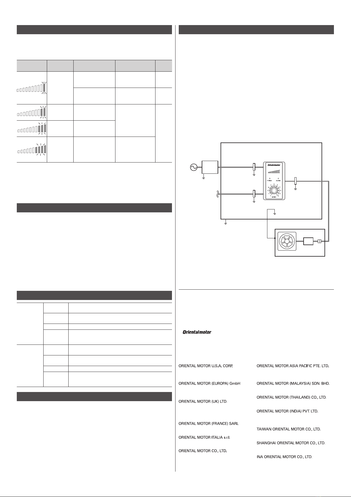
Example of installation and wiring
Cable
cramp
Power supply
cable
Signal cable
DC power
supply
Fan extension
cable
Ferrite
core
Shielded enclosure
Fan
(Ground panel)
Speed controller
Shielded cable
Grounding
Grounding
Grounding
Cable
cramp
Cable
cramp
Grounding
[2 m(6.6 ft.)]
Grounding
[2 m(6.6 ft.)]