manuals.online logo
Brands
  1. Home
  2. •
  3. Brands
  4. •
  5. Oriental motor
  6. •
  7. Controllers
  8. •
  9. Oriental motor DRL Series Operating and maintenance manual

Oriental motor DRL Series Operating and maintenance manual

HL-14076-2
Installation procedure
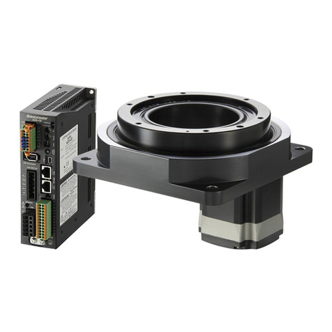
Compact Linear Actuator
DRL, DRL ⅡSeries
DRS Series
DRB Series Thank you for purchasing an Oriental Motor product.
This document describes contents required to check when performing installation
and maintenance so that a product can be used for a long term.
1. Notes about installation
•Assign qualified personnel of mechanical engineering to the task of installing compact linear actuators (hereinafter called actuator).
•For non-guide type actuators, misalignment of the central axis between the built-in screw nut and built-in screw shaft may cause
malfunction.
2. Notation on this manual
•Model name
This document describes the model name as "DR" in the case of the common description to the DRL Series, DRLⅡSeries, DRS Series, and
DRB Series.
•About this manual
This manual describes installation procedures of the products. Check with dimensions for the details of the product size.
•Symbol
Note This symbol indicates important handling instructions that users should observe to ensure safe use of the product.
3. Names and functions of parts
Names of parts are explained here.
•Non-guide type
This figure shows the non-guide type DRL28.
•Example of load mounting
Load mounting screw
An internal thread is
provided for the DR42
and DR60 types.
Motor
Screw shaft
Mounting hole
(4 locations)
Set collar
This prevents the screw shaft
from retracting completely
into the case.
Pilot
Adjusting Knob
This is the moving part
of the actuator.
Mounting plate
for actuator
Guide block
Guide rail
Movable plate
Positioning pin
Base plate
5. To design movable plate and mounting plate for actuator
Recommended dimensions for the movable plate and mounting plate for actuator are shown as follows. Use them as reference for design.
(X+Y) ± 0.05 (0.0020)
X Y
(X+Y) ± 0.1 (0.0039)
Mounting plate for actuatoMovable plate
A
B
ØD
B
ØC
ØR ØR 0.02
(0.0008) A
0.02
(0.0008) A
0.01
(0.0004) BA
0.01
(0.0004) B
Unit = mm (in.)
Applicable
product C D
DR20 3.3 (0.130) 16 +0.018
0 (H7) (0.63 +0.0007
0 )
DR28 3.3 (0.130) 22 +0.021
0 (H7) (0.87 +0.0008
0 )
DR42 4.5 (0.177) 25 +0.021
0 (H7) (0.98 +0.0008
0 )
DR60 9 (0.354) 36 +0.025
0 (H7) (1.42 +0.0010
0 )
•When using the centering adjustment plate
Unit = mm (in.)
Applicable
product CR
DR20 4 (0.16) 3.5 (0.14)
DR28 4 (0.16) 4 (0.16)
DR42 5 (0.20) 4 (0.16)
DR60 9 (0.35) 6 (0.24)
6. To design centering shaft and centering adjustment plate
Recommended dimensions for the centering shaft and centering adjustment plate are shown as follows. Use them as reference for design.
ØE
ØG
FH
P-P´
P´
P
• Centering adjustment plate
• Centering shaft
K I J
J
I
2×䠩
ØL
N0.02
(0.0008) N
When the periodic inspection is conducted, check that the centering shaft is free from flaw or wear.
Applicable
product E
[mm (in.)] F
[mm (in.)] G
[mm (in.)] H
[mm (in.)] K
[mm (in.)] L
[mm (in.)] M (Screw size)
(mm) Tighteningtorque *
[N・m (oz-in)]
DR20 16 −0.006
−0.017 (g6)
(0.63 −0.0002
−0.0007 )1.5
(0.059) 3 0
−0.02
(0.118 0
−0.0008 )10.5
(0.41) 0.01
(0.0004) 3 +0.010
0 (H7)
(0.118 +0.0004
0 )M2.5 0.4 (57)
DR28 22 −0.007
−0.020 (g6)
(0.87 −0.0003
−0.0008 )1.5
(0.059) 3 0
−0.02
(0.118 0
−0.0008 )10.5
(0.41) 0.01
(0.0004) 3 +0.010
0 (H7)
(0.118 +0.0004
0 )M3 0.6 (85)
DR42 25 −0.007
−0.020 (g6)
(0.98 −0.0003
−0.0008 )2
(0.079) 4 −0.004
−0.012
(0.157 −0.0002
−0.0005 )20
(0.79) 0.02
(0.0008) 4 +0.012
0 (H7)
(0.157 +0.0005
0 )M3 0.6 (85)
DR60 36 −0.009
−0.025 (g6)
(1.42 −0.0004
−0.0010 )2
(0.079) 8 −0.005
−0.014
(0.315 −0.0002
−0.0006 )24.5
(0.96) 0.02
(0.0008) 8 +0.015
0 (H7)
(0.315 +0.0006
0 )M5 3 (426)
* For the tightening torque, tighten the suitable force according to the material and thickness of the centering adjustment plate.
• Please contact your nearest Oriental Motor oce for further information.
Technical Support Tel:(800)468-3982
8:30 A.M. to 5:00 P.M., P.S.T. (M-F)
7:30 A.M. to 5:00 P.M., C.S.T. (M-F)
www.orientalmotor.com
Schiessstraße 74, 40549 Düsseldorf, Germany
Technical Support Tel:00 800/22 55 66 22
www.orientalmotor.de
Tel:01256-347090
www.oriental-motor.co.uk
Tel:01 47 86 97 50
www.orientalmotor.fr
Tel:02-93906346
www.orientalmotor.it
Tel:0800-060708
www.orientalmotor.com.tw
Singapore
Tel:1800-8420280
www.orientalmotor.com.sg
Tel:1800-806161
www.orientalmotor.com.my
Korea
Tel:080-777-2042
www.inaom.co.kr
4-8-1 Higashiueno, Taito-ku, Tokyo
110-8536 Japan
Tel:03-6744-0361
www.orientalmotor.co.jp
Tel:1800-888-881
www.orientalmotor.co.th
Tel:400-820-6516
www.orientalmotor.com.cn
Tel:+55-11-3266-6018
www.orientalmotor.com.br
Tel:+91-80-41125586
www.orientalmotor.co.in
Hong Kong Branch
Tel:+852-2427-9800
Published in March 2017
4. Installation procedure (example)
The installation procedure varies based on the accuracy of component parts of equipment.
•If centering is possible without adjustment of assembled parts due to high accuracy of each part, install in order of the Step 1, Step 2, Step 3-A, and Step 4.
•If centering is not easy because of low-accuracy parts, install in order of the Step 1, Step 2, Step 3-B, and Step 4.
Step 1 Installing a guide rail
1. In order to set the position of the guide rail and mounting plate for actuator,
install positioning pins on the base plate.
Intersect at a right angle
Positioning pin
2. Secure a guide rail using screws while pressing the reference surface of
the guide rail to the positioning pin.
Positioning pin
Reference surface
of the guide rail Positioning pin
*Check the manufacturer of a guide rail
for the position of the reference surface
of the guide rail.
Step 2 Installing a mounting plate
Secure a mounting plate for actuator using screws after positioning it with the
positioning pins on the base plate.
Provide a mounting plate for actuator with reference to "5. To design movable
plate and mounting plate for actuator."
Positioning pin
Step 3-A Installing a movable plate (If centering is possible without adjustment of assembled parts due to high accuracy of each part)
1. In order to set the position of the movable plate and guide block,
install positioning pins on the movable plate.
Positioning pin
Screw shaft
mounting hole
Note Design a screw shaft mounting hole in consideration
of a margin so that stacked tolerances of parts can be
absorbed. Provide a mounting plate for actuator with
reference to "5. To design movable plate and mounting
plate for actuator."
2. Secure the movable plate with screws while pressing the
positioning pins on the movable plate to the reference surface of
the guide block.
Reference surface
of guide block
Positioning pin
*Check the manufacturer of a guide rail for the
position of the reference surface of the guide block.
Step 3-B Installing a movable plate (If centering is not easy because of low-accuracy parts)
3. Install the movable plate by either of the following methods.
•Place the movable plate and mounting plate for actuator
together, and secure with screws so that there is no gap
between them.
•Put a block gauge or similar parts between the movable plate
and mounting plate for actuator, and secure with screws so that
there is no gap.
If there is a gap, reinstall the movable plate.
No gap
No gap
Block gauge
∗㻌If there is a distance between the movable plate and mounting plate
for actuator, use a block gauge or similar parts.
4. Fit the centering shaft with the pilot of the mounting plate for
actuator, and align the centering shaft with the central axis of the
screw shaft mounting hole on the centering adjustment plate.
5. Slide the movable plate back and forth, and secure the movable
plate and centering adjustment plate with screws after checking
that the movable plate can move smoothly so that the centering
shaft does not contact.
If the movable plate does not move smoothly, adjust axis
misalignment between the centering shaft and the centering
adjustment plate while moving the centering adjustment plate
from right to left or up and down.
㻼㼕㼘㼛㼠㻌㼛㼒㻌㼙㼛㼡㼚㼠㼕㼚㼓
㼜㼘㼍㼠㼑㻌㼒㼛㼞㻌㼍㼏㼠㼡㼍㼠㼛㼞
Screw shaft mounting hole
of centering adjustment plate
Centering shaft
Centering adjustment plate
Adjust axis misalignment between the centering shaft and the
centering adjustment plate in the upper, lower, right,
and left directions, using the centering adjustment plate
Note
•Provide a centering shaft with reference to "6. To
design centering shaft and centering adjustment
plate."
•Design the centering adjustment plate and pilot of
the mounting plate for actuator according to the
centering shaft.
Step 4 Installing the screw shaft and
movable plate
1. Secure a compact linear actuator to the mount plate for actuator with
screws.
Model Screw size Tightening torque
[N·m(oz-in)]
DR20 M2 0.4 (57)
DR28 M2.5 0.6 (85)
DR42 M4 1.8 (256)
DR60 M5 5 (710)
2. Push the screw shaft into the actuator body once until the set collar stops,
and then pull it out a little. Adjust the screw shaft length to be pulled out so
that the set collar does not contact the actuator body when the screw shaft
is tightened with tools.
3. Secure the screw shaft with a nut after pass it through the screw shaft hole
on the movable plate. (Secure the DR42 and DR60 with a screw.)
Model Screw size Tightening
torque
[N·m(oz-in)]
DR20
DR28 M3 nut 0.6 (85)
DR42 M4 screw 1.8 (256)
DR60 M8 screw 5 (710)
4. Perform test operation to check if there is no place to generate abnormal
noises.
This manual suits for next models

7

Other Oriental motor Controllers manuals

Oriental motor EAS Series User manual

Oriental motor

Oriental motor EAS Series User manual

Oriental motor DSC Series User manual

Oriental motor

Oriental motor DSC Series User manual

Oriental motor DGII Series User manual

Oriental motor

Oriental motor DGII Series User manual

Oriental motor DR Series User manual

Oriental motor

Oriental motor DR Series User manual

Oriental motor FLEX RK II Series User manual

Oriental motor

Oriental motor FLEX RK II Series User manual

Oriental motor DRLII Series User manual

Oriental motor

Oriental motor DRLII Series User manual

Oriental motor LIMO EZS Series User manual

Oriental motor

Oriental motor LIMO EZS Series User manual

Oriental motor DR Series User manual

Oriental motor

Oriental motor DR Series User manual

Oriental motor AZ series User manual

Oriental motor

Oriental motor AZ series User manual

Oriental motor EZS Series User manual

Oriental motor

Oriental motor EZS Series User manual

Oriental motor CM10 Series User manual

Oriental motor

Oriental motor CM10 Series User manual

Oriental motor ES01 User manual

Oriental motor

Oriental motor ES01 User manual

Oriental motor FSC-24 User manual

Oriental motor

Oriental motor FSC-24 User manual

Oriental motor EZ limo ESMC-K User manual

Oriental motor

Oriental motor EZ limo ESMC-K User manual

Oriental motor Astep AZ Series User manual

Oriental motor

Oriental motor Astep AZ Series User manual

Oriental motor aSTEP AZ Series User manual

Oriental motor

Oriental motor aSTEP AZ Series User manual

Oriental motor DRS2 Series User manual

Oriental motor

Oriental motor DRS2 Series User manual

Oriental motor EMP400 Series User manual

Oriental motor

Oriental motor EMP400 Series User manual

Oriental motor CRK Series Owner's manual

Oriental motor

Oriental motor CRK Series Owner's manual

Oriental motor DSC Series User manual

Oriental motor

Oriental motor DSC Series User manual

Oriental motor TM Series User manual

Oriental motor

Oriental motor TM Series User manual

Oriental motor SCX11 Installation and operation manual

Oriental motor

Oriental motor SCX11 Installation and operation manual

Oriental motor aSTEP AZ Series User manual

Oriental motor

Oriental motor aSTEP AZ Series User manual

Oriental motor A Step AZ Series User manual

Oriental motor

Oriental motor A Step AZ Series User manual

Popular Controllers manuals by other brands

BEAK SD Series user manual

BEAK

BEAK SD Series user manual

ABB ControlIT 53MC5000 instruction manual

ABB

ABB ControlIT 53MC5000 instruction manual

Curtis 1310 manual

Curtis

Curtis 1310 manual

spega BSK4-F Technical manual

spega

spega BSK4-F Technical manual

EAS Electric ECEN Series instruction manual

EAS Electric

EAS Electric ECEN Series instruction manual

White Rodgers 24A06G-1 installation instructions

White Rodgers

White Rodgers 24A06G-1 installation instructions

Fortinet FortiWLC-500D quick start guide

Fortinet

Fortinet FortiWLC-500D quick start guide

Power Electronics V5 Series Getting started manual

Power Electronics

Power Electronics V5 Series Getting started manual

Torqeedo TorqLink operating manual

Torqeedo

Torqeedo TorqLink operating manual

Mitsubishi Melsec A user manual

Mitsubishi

Mitsubishi Melsec A user manual

Matelec FPC-30220 Owner's operation manual

Matelec

Matelec FPC-30220 Owner's operation manual

EasyIO FW-14 V3 instruction manual

EasyIO

EasyIO FW-14 V3 instruction manual

Texas Instruments TMS320C6000 DSP reference guide

Texas Instruments

Texas Instruments TMS320C6000 DSP reference guide

Regner RA MINI Series user manual

Regner

Regner RA MINI Series user manual

National Instruments Quanser QNET 2.0 Set up and configuration

National Instruments

National Instruments Quanser QNET 2.0 Set up and configuration

KRAFTWERK RS1 manual

KRAFTWERK

KRAFTWERK RS1 manual

Toho Electronics TTM-P4W Series instruction manual

Toho Electronics

Toho Electronics TTM-P4W Series instruction manual

Playlearn BTLBC instructions

Playlearn

Playlearn BTLBC instructions

manuals.online logo
manuals.online logoBrands
  • About & Mission
  • Contact us
  • Privacy Policy
  • Terms and Conditions

Copyright 2025 Manuals.Online. All Rights Reserved.