manuals.online logo
Brands
  1. Home
  2. •
  3. Brands
  4. •
  5. Oriental motor
  6. •
  7. Controllers
  8. •
  9. Oriental motor DH Series User manual

Oriental motor DH Series User manual

1
Introduction
Before use
Only qualied personnel of electrical and mechanical engineering should work with the
product.
Use the product correctly after thoroughly reading the section “Safety precautions.”
In addition, be sure to observe the contents described in warning, caution, and note in
this manual.
The product described in this manual is designed and manufactured to be incorporated
in general industrial equipment. Do not use for any other purpose. Oriental Motor Co.,
Ltd. Is not responsible for any compensation for damage caused through failure to
observe this warning.
Overview of the product
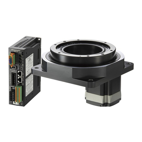
The hollow rotary actuator DH Series (hereinafter referred to as“actuator”) is an actuator
that a hollow table is used for the output shaft of a 5-phase stepping motor.
Safety precautions
The precautions described below are intended to ensure the safe and correct use of the
product, and to prevent the customer and others from exposure to the risk of injury. Use
the product only after carefully reading and fully understanding these instructions.
You must not operate the actuator (operate the equipment for the specied purpose)
if the machine in which the actuator is installed does not satisfy the related safety
standards. The factory safety manager or safety personnel in charge of the applicable
machine must ensure that the machine is operated only by qualied personnel who
are familiar with the operation of electronic equipment, and thereby prevent injury or
damage to the equipment.
The term “qualied personnel” refers to persons who have received the necessary
training or education and have pertinent experience; who are familiar with the relevant
standards, regulations, accident-prevention rules and inspection conditions; who are
authorized by the factory safety manager to engage in the necessary activities; and who
have the ability to discern and prevent potential dangers.
Handling the product without observing the instructions that
accompany a“WARNING” symbol may result in serious injury
or death.
Handling the product without observing the instructions
that accompany a“CAUTION”symbol may result in injury or
property damage.
The items under this heading contain important handling
instructions that the user should observe to ensure the safe
use of the product.
The items under this heading contain related information and
contents to gain a further understanding of the text in this
manual.
HL-14121
OPERATING MANUAL Thank you for purchasing an Oriental Motor product.
This Operating Manual describes product handling procedures and safety precautions.
yPlease read it thoroughly to ensure safe operation.
yAlways keep the manual where it is readily available.
Hollow Rotary Actuator
DH Series Actuator Edition
General
yDo not use the product in explosive or corrosive environments, in the presence of
ammable gases, in places subjected to splashing water, or near combustibles. Doing
so may result in re or injury.
yAssign qualied personnel to the task of installing, wiring, operating/controlling,
inspecting, and troubleshooting the product. Handling by unqualied personnel may
result in re, injury, or damage to equipment.
yDo not transport, install, connect or inspect the product while the power is supplied.
Doing so may result in electric shock.
yProvide an emergency stop device or emergency stop circuit external to the
equipment so that the entire equipment will operate safely in the event of a system
failure or malfunction. Failure to do so may result in injury.
yWhen an alarm is generated in the driver (any of the driver's protective functions
is triggered), take measures to hold the moving part in a specic position since the
actuator stops and loses its holding torque. Failure to do so may result in injury or
damage to equipment.
yWhen having replaced the driver, set the resolution, the traveling direction or others
before operating. If the actuator is operated without setting the resolution or the
traveling direction, the output table may move to unexpected directions or run at
unexpected speeds, leading to injury or mechanical damage.
Installation
yInstall the actuator inside an enclosure. Failure to do so may result in injury.
yWhen installing the actuator, install it inside an enclosure so that it is out of the direct
reach of users. Be sure to ground if users can touch it. Failure to do so may result in
electric shock.
Connection
yDo not forcibly bend, pull, or pinch the lead wire or cable. Doing so may result in re.
Repair, disassembly, and modication
yDo not disassemble or modify the actuator. Doing so may result in injury or damage to
equipment.
General
yDo not use the actuator beyond its specications. Doing so may result in injury or
damage to equipment.
yKeep your ngers and objects out of the openings in the actuator. Failure to do so may
result in re, electric shock or injury.
yDo not touch the actuator during operation or immediately after stopping. The surface
is hot, and this may cause a skin burn(s).
yDo not carry the actuator by holding the moving part, lead wire, or cables. Doing so
may cause injury.
Installation
yDo not place combustibles around the actuator. Doing so may result in re or a skin
burn(s).
yDo not leave anything around the actuator that would obstruct ventilation. Doing so
may result in damage to equipment.
Operation
yUse an actuator and a driver only in the specied combination. An incorrect
combination may cause a re.
yDo not touch the moving part during operation. Doing so may cause injury.
yWhile the actuator is operated, do not make the lead wire contact with the moving
part. Doing so may result in disconnection in the lead wire, leading to electric shock or
damage.
yThe motor surface temperature may exceed 70 °C (158 °F) even
under normal operating conditions. If the operator is allowed to
approach the actuator in operation, ax a warning label shown in
the gure on a conspicuous position. Warning label
Introduction .................................................1
Safety precautions ......................................1
Precautions for use......................................2
Preparation...................................................2
Installation....................................................3
Connection ...................................................3
Inspection and maintenance ....................4
Specications ...............................................4
Regulations and standards........................4
2
Precautions for use
This section covers restrictions and requirements the user should consider when using
the product.
•When conducting the insulation resistance measurement or the
dielectric strength test, be sure to separate the connection between the
actuator and the driver.
Conducting the insulation resistance measurement or dielectric strength test with the
actuator and the driver connected may result in damage to the product.
•Do not apply an axial load and moment load in excess of the specied
permissible limit
Be sure to operate the actuator within the specied permissible limit of axial load and
moment load. Continuing to operate the actuator under a axial load or moment load
exceeding the permissible value may cause malfunction or shorter service life of the
actuator.
•Use the actuator in conditions where the motor surface temperature
does not exceed 100 °C (212 °F).
If the motor surface temperature exceeds 100 °C (212 °F) due to the operating conditions
(ambient temperature, operating speed, operating duty, etc.), the motor windings may
burn out or the lifetime of the bearings (ball bearings) may be reduced.
•Rotation direction of output table
The rotation direction of the output table varies depending on the setting of the travel
amount or the input method of the pulse signal.
Setting Rotation direction of output
table
Operation by setting of parameter
Set the travel amount to the positive (+) direction CW
(Positive
direc
tion)
Operation by pulse signal
y2-pulse input mode
Input the pulse signal to the CW input
y1-pulse input mode
Input the pulse signal to the PLS input while the
DIR input is ON.
Operation by setting of parameter
Set the travel amount to the negative (−) direction CCW
(Negative
direction)
Operation by pulse signal
y2-pulse input mode
Input the pulse signal to the CCW input
y1-pulse input mode
Input the pulse signal to the PLS input while the
DIR input is OFF.
•Holding torque at standstill
The motor holding torque is reduced by the current cutback function of the driver
at actuator standstill. When selecting a actuator, check the holding torque at motor
standstill in the specications on the catalog.
zNotes when the connection cable is used
Note the following points when our cable is used.
•When inserting the connector
Hold the connector main body, and insert it in straight securely. Inserting the connector
in an inclined state may result in damage to connector or a connection failure.
•When pulling out the connector
Hold both ends of the connector main body, and pull out it straight. Pulling out the
connector with holding the lead wire may result in damage to the connector.
Secure the lead wires at the connection part of the connector to prevent the
connector or terminals from receiving stress due to bending or self-weight of
lead wires. Also, do not excessively bend the lead wires near the connection
part of the connector. Applying stress on the lead wires may cause poor
contact or disconnection, leading to malfunction or heat generation.
Preparation
Checking the product
Verify that the items listed below are included. Report any missing or damaged items to
the Oriental Motor sales oce from which you purchased the product.
yHollow rotary actuator .......................................... 1 unit
yOPERATING MANUAL Actuator Edition ........... 1 copy (this manual)
How to identify the product model
DHM 28 P A K 2
1 2 3 4 5 6
1 Series DHM: DH Series
2 Motor frame size 28: 28 mm (1.10 in.)
42: 42 mm (1.65 in.)
3 Type of motor P: 5-phase stepping motor
4 Shape of motor A: Standard
5 Specication of motor K: DC power input type
6 Reference number
Information about nameplate
The gure shows an example.
Ac
tuator model
Manufacturing dateSerial number
Specications
The position describing the information may vary depending on the product.
Names and functions of parts
The area indicated in gray color represents a moving part.
The gure shows the DHM28PAK2.
Pilot Motor
Output table
Mounting holes
(4 places)
Load-positioning pin hole
(1 place)
Screw holes for manufacturing
(3 places) *1
L
oad-mounting screw holes
(4 places)
Connector *2

Connector pin No.
15
*1 These are holes for manufacturing. Do not use them.
*2 The DHM42PAK is an actuator of the lead wire type.
3
Applicable connector and lead wire
Actuator model Type Manufacturer model
DHM28PAK2
Connector housing 51065-0500 (Molex Incorporated)
Contact 50212-8XXX (Molex Incorporated)
Designated crimping tool 63819-0500 (Molex Incorporated)
Applicable lead wire
AWG24 (0.2 mm2)
Outer sheath diameter:
ø1.4 mm (ø0.055 in.) or less
Stripping length of wire insulation:
1.3 to 1.8 mm (0.051 to 0.071 in.)
Drivers possible to combine
Actuator model
Driver model
Pulse input type RS-485 communication
type Built-in controller type
DHM28PAK2
DHM42PAK
CVD507BR-K
CVD507B-K
CVD507-K
CVD5BR-KR
CVD5B-KR CRD507-KD
Installation
This section explains the installation environment and installation method of the
actuator, and the installation method of a load.
Installation location
The actuator is designed and manufactured to be incorporated in equipment.
Install it in a well-ventilated location that provides easy access for inspection.
The location must also satisfy the following conditions:
yInside an enclosure that is installed indoors (provide vent holes)
yOperating ambient temperature: 0 to +40 °C (+32 to +104 °F) (non-freezing)
yOperating ambient humidity: 85 % or less (non-condensing)
yArea free of explosive atmosphere, toxic gas (such as sulfuric gas), or liquid
yArea not exposed to direct sun
yArea free of excessive amount of dust, iron particles or the like
yArea not subject to splashing water (rain, water droplets), oil (oil droplets) or other
liquids
yArea free of excessive salt
yArea not subject to continuous vibrations or excessive shocks
yArea free of excessive electromagnetic noise (from welders, power machinery, etc.)
yArea free of radioactive materials, magnetic elds or vacuum
y1,000 m (3,300 ft.) or lower above sea level
Installation method
The actuator can be installed in any
direction.
Install the actuator onto an appropriate
at metal plate having excellent vibration
resistance and heat conductivity.
When installing the actuator, use four
mounting holes and secure the actuator
with four screws (not included) so that
there is no gap between the actuator
and the metal plate.
Values of the tightening torque are
recommended. Tighten the screws with
a suitable torque according to the design
conditions of the load.
Flange pilot
Metal plate
Mounting holes
Pilot
Fit the pilot located on the actuator mounting surface into a ange pilot.
Model Nominal size Tightening torque Eective depth of
screw thread
DHM28PAK2 M2.5 0.5 N·m (71 oz-in) 5 mm (0.20 in.)
DHM42PAK M3 1 N·m (142 oz-in)
Installing a load
Install a load with screws using the load-mounting screw holes (four places) on the
output table. Use the load-positioning pin hole (one place) of the output table when
positioning a load.
Values of the tightening torque are recommended. Tighten the screws with a suitable
torque according to the design conditions of the load.
Specications of load-mounting screw holes
Model Nominal size Tightening torque Eective depth of
screw thread
DHM28PAK2 M2.5 0.5 N·m (71 oz-in) 3 mm (0.12 in.)
DHM42PAK M4 2 N·m (280 oz-in) 4 mm (0.16 in.)
Specications of load-positioning pin hole
Model Diameter Depth
DHM28PAK2 ø3
+0.01
0
mm (0.1181
+0.0004
0
in.) 3 mm (0.12 in.)
DHM42PAK ø4
+0.012
0
mm (0.1575
+0.0005
0
in.) 4 mm (0.16 in.)
Be sure to secure the positioning pin to the load side. Driving the positioning
pin to the output table may damage bearings due to an impact or an
excessive moment of inertia.
Permissible axial load and permissible moment load
The axial load and moment load on the output table must be kept the under the
permissible values listed in the table below.
Model Permissible axial load Permissible moment load
DHM28PAK2 40 N (9 lb.) 0.1 N·m (14.2 oz-in.)
DHM42PAK 150 N (33 lb.) 0.4 N·m (56 oz-in.)
If the operation is continued in a state where the axial load or moment load
in excess of the permissible values is applied, causing the output table or
bearings (ball bearings) to damage.
zHow to calculate loads
This example explains how to calculate a load when an external force F (N) is applied to a
position that is extended L (m) in the horizontal direction from the center of the output
ange.
How to read a code
yΔM: Load moment (N·m)
yF : External force (N)
yL : Overhang distance (m)
yM : Permissible moment load (N·m)
yΔF: Load applied on the output ange
surface (N)
ym : Mass of a load (kg)
yg : Gravitational acceleration (m/s2)
yFs : Permissible axial load (N)
yLoad moment
ΔM = F · L
ΔM ≤ M
yAxial load
ΔF = F + m · g
ΔF ≤ Fs
Fulcrum point
L
F
ΔM
mg
Connection
Refer to the following table when connecting with the drivers of Oriental Motor.
For details, refer to operating manual of the driver.
12345Pin No.
Driver
Pin No.
Connector-coupled type Lead wires type
Pin No. Lead wire color * Lead wire color
1 1 Blue Blue
2 2 Red Red
3 3 Orange Orange
4 4 Green Green
5 5 Black Black
* It indicates the lead wire color of the connection cable
of Oriental Motor.
4
yUnauthorized reproduction or copying of all or part of this manual is prohibited.
yOriental Motor shall not be liable whatsoever for any problems relating to industrial
property rights arising from use of any information, circuit, equipment or device
provided or referenced in this manual.
yCharacteristics, specications and dimensions are subject to change without notice.
yWhile we make every eort to oer accurate information in the manual, we welcome
your input. Should you nd unclear descriptions, errors or omissions, please contact
your nearest Oriental Motor sales oce.
yis a registered trademark or trademark of Oriental Motor Co., Ltd., in
Japan and other countries.
© Copyright ORIENTAL MOTOR CO., LTD. 2021
Published in December 2021
T
echnical Support Tel:800-468-3982
8:30am EST to 5:00pm PST (M-F)
www
.orientalmotor.com
• Please contact your nearest Oriental Motor oce for further information.
Schiessstraße 44, 40549 Düsseldor
f, Germany
T
echnical Support Tel:00 800/22 55 66 22
www
.orientalmotor.de
Unit 5 F
araday Oce Park, Rankine Road,
Basingstoke
, Hampshire RG24 8QBUK
T
el:+44-1256347090
www
.oriental-motor.co.uk
T
el:+33-1 47 86 97 50
www
.orientalmotor.fr
T
el:+39-02-93906347
www
.orientalmotor.it
4-8-1Higashiueno
,Taito-ku,Tokyo 110-8536
Japan
T
el:+81-3-6744-0361
www
.orientalmotor.co.jp
Tel:400-820-6516
www.orientalmotor.com.cn
Tel:0800-060708
www.orientalmotor.com.tw
Singapore
Tel:1800-842-0280
www.orientalmotor.com.sg
Tel:1800-806-161
www.orientalmotor.com.my
Tel:1800-888-881
www.orientalmotor.co.th
Korea
Tel:080-777-2042
www.inaom.co.kr
Tel:1800-120-1995 (For English)
1800-121-4149 (For Hindi)
www.orientalmotor.co.in
Inspection and maintenance
It is recommended that periodic inspections are conducted for the items listed below
after each operation of the actuator. If an abnormal condition is noted, discontinue any
use and contact your nearest Oriental Motor sales oce.
Maintenance item
yCheck if any of the screws having installed the actuator is loose.
yCheck if an unusual noise is generated from the actuator.
yCheck if a damage or stress is applied on the lead wire.
yCheck if the connection part between the actuator and driver is loose.
Warranty
Check on the Oriental Motor Website for the product warranty.
Disposal
Dispose the product correctly in accordance with laws and regulations, or instructions of
local governments.
Specications
Product specication
Check on the Oriental Motor Website for the product specications.
General specications
Operation
environment
Ambient
temperature 0 to +40 °C (+32 to +104 °F) (non-freezing)
Ambient
humidity 85 % or less (non-condensing)
Altitude Up to 1,000 m (3,300 ft.) above sea level
Shipping
environment
Storage
environment
Ambient
temperature −20 to +60 °C (−4 to +140 °F) (non-freezing)
Ambient
humidity 85 % or less (non-condensing)
Altitude Up to 3,000 m (10,000 ft.) above sea level
Heat resistance
class 130 (B)
Insulation
resistance
100 MΩ or more when 500 VDC megger is applied between the
case and the motor windings.
Dielectric
strength
Sucient to withstand the following conditions applied between
the case and the motor windings for 1 minute.
DHM28: AC0.5 kV 50 Hz or 60 Hz
DHM42: AC1.0 kV 50 Hz or 60 Hz
Regulations and standards
CE Marking
zEMC Directive
The actuator conforms to the EMC Directive in a state where the motor is connected with
the driver. For details, refer to operating manual of the driver.
RoHS Directive
This product does not contain the substances exceeding the restriction values.

This manual suits for next models

2

Other Oriental motor Controllers manuals

Oriental motor Astep AZ Series User manual

Oriental motor

Oriental motor Astep AZ Series User manual

Oriental motor DR Series User manual

Oriental motor

Oriental motor DR Series User manual

Oriental motor aSTEP AZ Series User manual

Oriental motor

Oriental motor aSTEP AZ Series User manual

Oriental motor EZ limo ESMC-K2 User manual

Oriental motor

Oriental motor EZ limo ESMC-K2 User manual

Oriental motor EAS Series User manual

Oriental motor

Oriental motor EAS Series User manual

Oriental motor DRL Series User manual

Oriental motor

Oriental motor DRL Series User manual

Oriental motor AR Series User manual

Oriental motor

Oriental motor AR Series User manual

Oriental motor DRL Series User manual

Oriental motor

Oriental motor DRL Series User manual

Oriental motor DRLII Series User manual

Oriental motor

Oriental motor DRLII Series User manual

Oriental motor AZ Series User manual

Oriental motor

Oriental motor AZ Series User manual

Oriental motor FSC-24 User manual

Oriental motor

Oriental motor FSC-24 User manual

Oriental motor DGII Series User manual

Oriental motor

Oriental motor DGII Series User manual

Oriental motor DG Series User manual

Oriental motor

Oriental motor DG Series User manual

Oriental motor TM Series User manual

Oriental motor

Oriental motor TM Series User manual

Oriental motor FLEX RK II Series User manual

Oriental motor

Oriental motor FLEX RK II Series User manual

Oriental motor CRK Series Owner's manual

Oriental motor

Oriental motor CRK Series Owner's manual

Oriental motor DGII Series User manual

Oriental motor

Oriental motor DGII Series User manual

Oriental motor ASTEP AZ Series User manual

Oriental motor

Oriental motor ASTEP AZ Series User manual

Oriental motor CRD514-KD Owner's manual

Oriental motor

Oriental motor CRD514-KD Owner's manual

Oriental motor DRS Series User manual

Oriental motor

Oriental motor DRS Series User manual

Oriental motor DG Series User manual

Oriental motor

Oriental motor DG Series User manual

Oriental motor DRL Series User manual

Oriental motor

Oriental motor DRL Series User manual

Oriental motor EZS Series User manual

Oriental motor

Oriental motor EZS Series User manual

Oriental motor CRD5103P-RS4 User manual

Oriental motor

Oriental motor CRD5103P-RS4 User manual

Popular Controllers manuals by other brands

Fanvil PA2 How-to

Fanvil

Fanvil PA2 How-to

Evco Vcolor 318 M Installer manual

Evco

Evco Vcolor 318 M Installer manual

Johnson Controls F4-CV Series installation guide

Johnson Controls

Johnson Controls F4-CV Series installation guide

Sigma Controls 100 Series instruction manual

Sigma Controls

Sigma Controls 100 Series instruction manual

Lutron Electronics LHD0-96W24V-U UL manual

Lutron Electronics

Lutron Electronics LHD0-96W24V-U UL manual

Watlow Power Series Specifications

Watlow

Watlow Power Series Specifications

MSA GasGard XL Quick start guides

MSA

MSA GasGard XL Quick start guides

Azoteq ProxSense Series user guide

Azoteq

Azoteq ProxSense Series user guide

SURAN ENDA EUP Series manual

SURAN

SURAN ENDA EUP Series manual

SMC Corporation LEC-BCW Series Operation manual

SMC Corporation

SMC Corporation LEC-BCW Series Operation manual

Honeywell HON 5020 User and maintenance manual

Honeywell

Honeywell HON 5020 User and maintenance manual

Field Controls HHSC+ user manual

Field Controls

Field Controls HHSC+ user manual

STIEBEL ELTRON CNS Series quick start guide

STIEBEL ELTRON

STIEBEL ELTRON CNS Series quick start guide

Douglas Dynamics Western 85200 operating instructions

Douglas Dynamics

Douglas Dynamics Western 85200 operating instructions

Ss Brewtech FTSs2 Product guide

Ss Brewtech

Ss Brewtech FTSs2 Product guide

cashco PGR-2 Installation, operation & maintenance manual

cashco

cashco PGR-2 Installation, operation & maintenance manual

IR ARO 6744 Series Operator's manual

IR

IR ARO 6744 Series Operator's manual

Mitsubishi Electric MELSEC Q Series quick start guide

Mitsubishi Electric

Mitsubishi Electric MELSEC Q Series quick start guide

manuals.online logo
manuals.online logoBrands
  • About & Mission
  • Contact us
  • Privacy Policy
  • Terms and Conditions

Copyright 2025 Manuals.Online. All Rights Reserved.