36
4 CONFIGURATION OF THE CONTROL PANEL
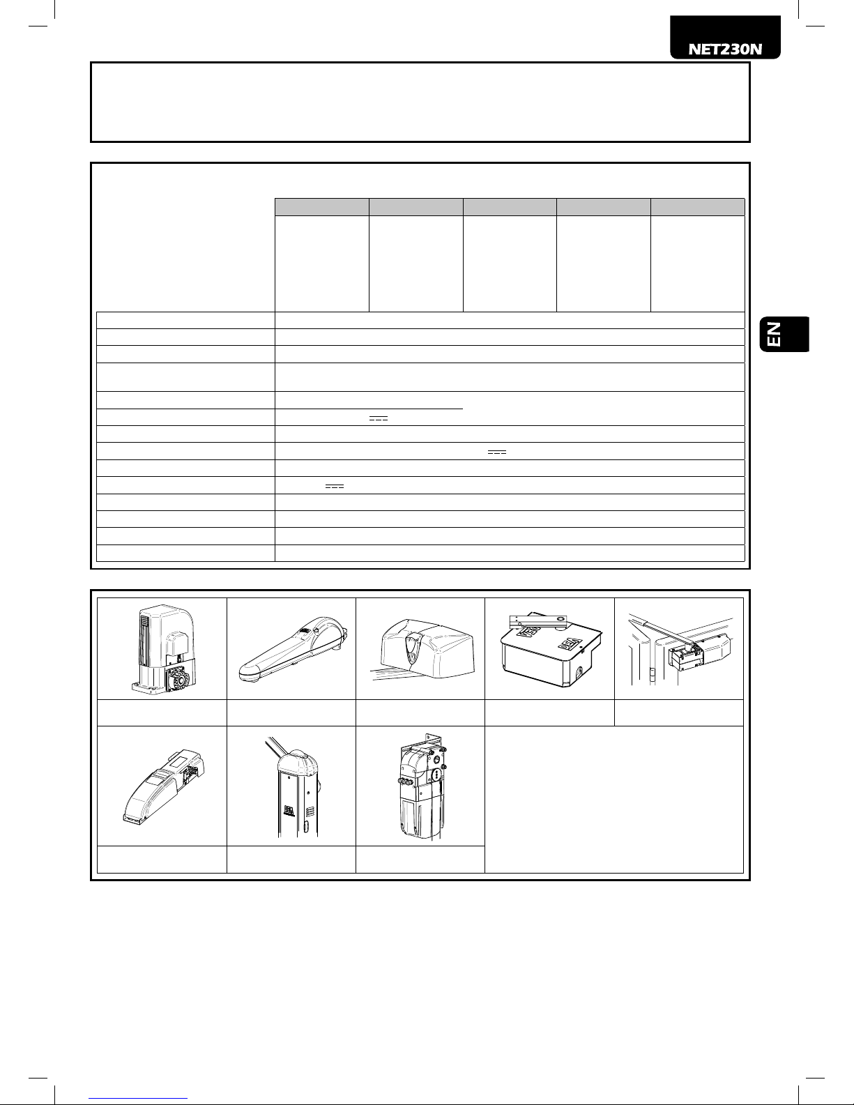
The universal control unit NET230N can be used for the management of the following types ( ) of closures motorized by DEA Sy-
stem: swing and sliding gates, overhead doors and barriers.
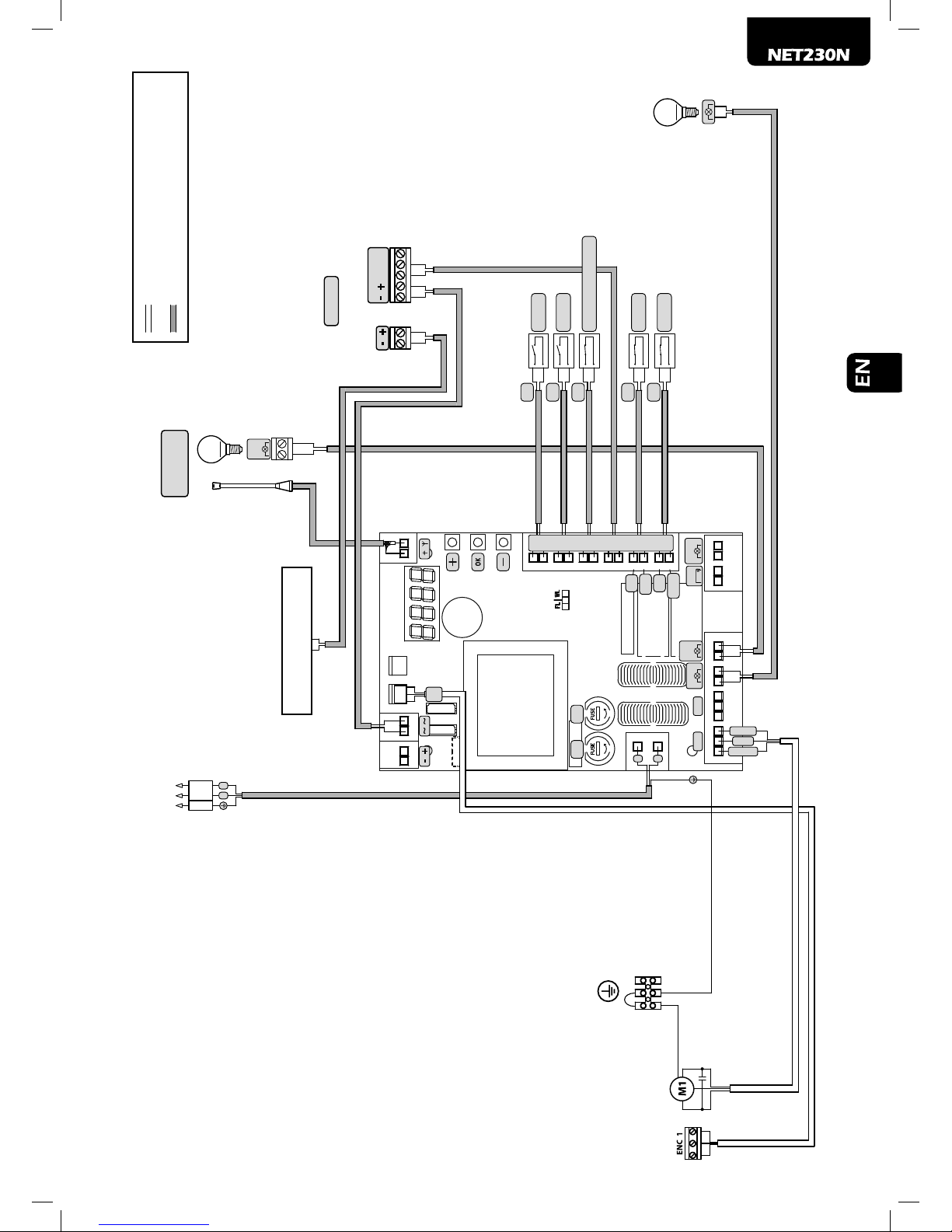
In order to ensure maximum adaptability to each of closure, the control board provides an initial procedure, performed only at the
rst turn, for the optimal conguration of inputs, outputs and parameters (see diagram ). Once congured, the control panel will operate
in the mode “dedicated” to the of selected closing. After performing the initial conguration it is sufcient to execute the standard
programming for the installation on which it is operating.
All settings remain in memory even in the case of subsequent are-ups (see diagram ).
If necessary the of congured closing can be later adjusted following diagram .
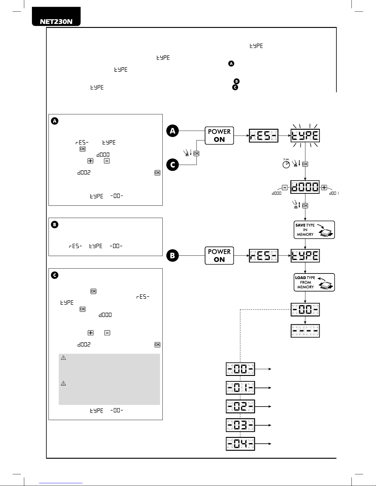
FIRST CONTROL BOARD IGNITION
Conguration after the rst ignition
For the rst control panel ignition, proceed as fol-
lows:
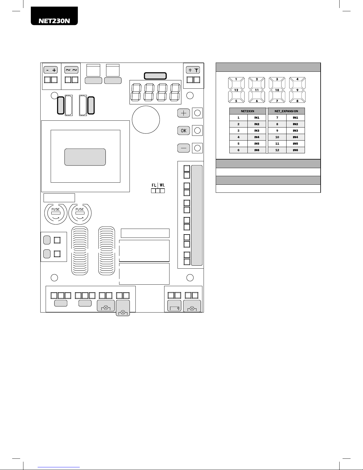
1. Apply power, the display shows in sequence the
writing “ ” and “ ” ashing;
2. Press the button and hold for 5 seconds until
the display shows on the display;
3. Acting on the and keys, select the desired
conguration depending on the type of installa-
tion (es. ) and conrm by pressing the
button;
At this point, the selection will be stored and relo-
aded each time in the future.
4. Follow signs, “ ”, “ ” followed by the
symbol of closed gate “- - - - ”.
Following ignitions
If you have already saved a conguration, pro-
ceed as follows:
Apply power, the display shows in sequence the
writing “ ”, “ ”, “ ” followed by the
symbol of closed gate “- - - - ”.
Modify the existing conguration
If you have already saved a conguration and you
want to change it, proceed as follows:
1. Hold down the button and give power, the di-
splay shows in sequence the writing “” and
“” ashing;
2. Press the button and hold for 5 seconds until
the display shows (the value changes to
match the previous conguration used) on the
display;
3. Acting on the and ,select the new desired
conguration depending on the type of installa-
tion (es. ) and conrm by pressing the
button;
Stop the reconguration procedure prior
to conrmation, involves loading the previous
conguration by the control panel without any
modication.
However, if the reconguration procedure is
brought to an end, the new conguration will
take the place of the previous one and will be
reloaded each time in the future.
4. Follow signs, “ ”, “ ” followed by the
symbol of closed gate “- - - - ”.
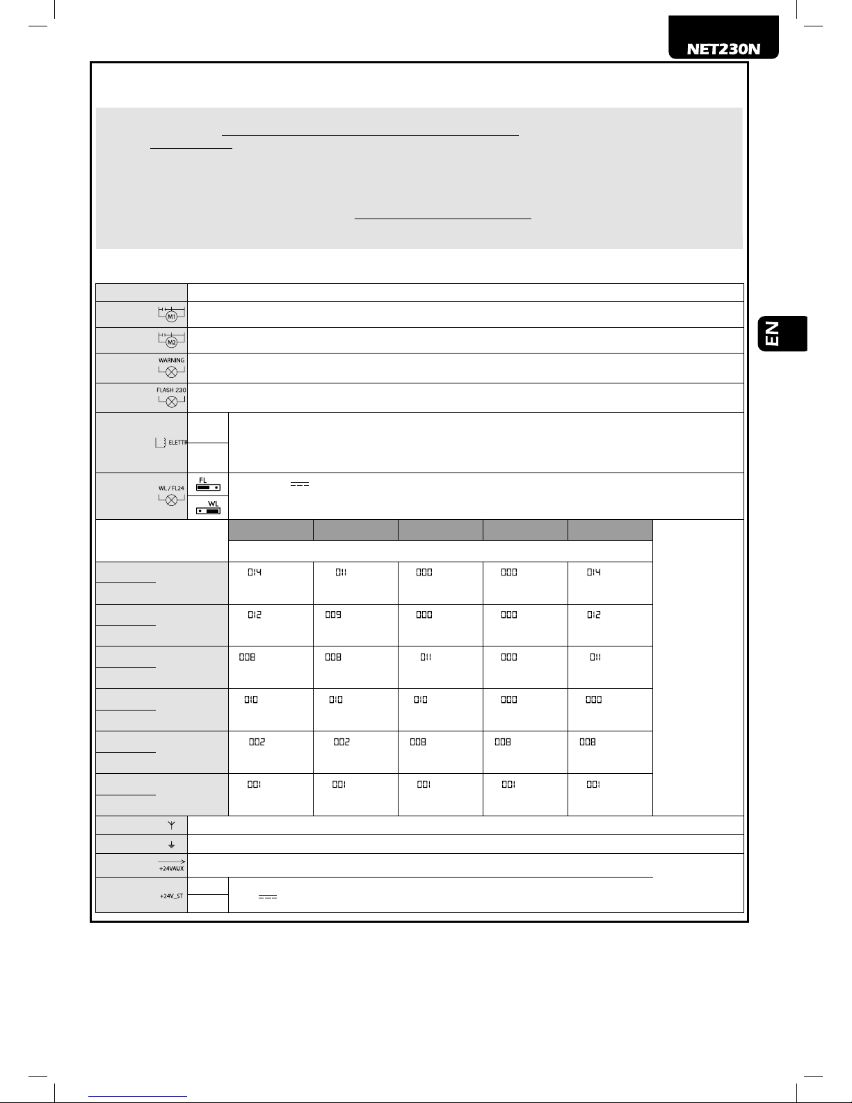
Sliding gates
Swing gates
Overhead doors
Barriers
Sectional doors