6 7
844·674·4461
TECHSUPPORT@ORIGINACOUSTICS.COM WWW.ORIGINACOUSTICS.COM
COMPOSER LCR SERIES INSTRUCTION MANUAL
Installation
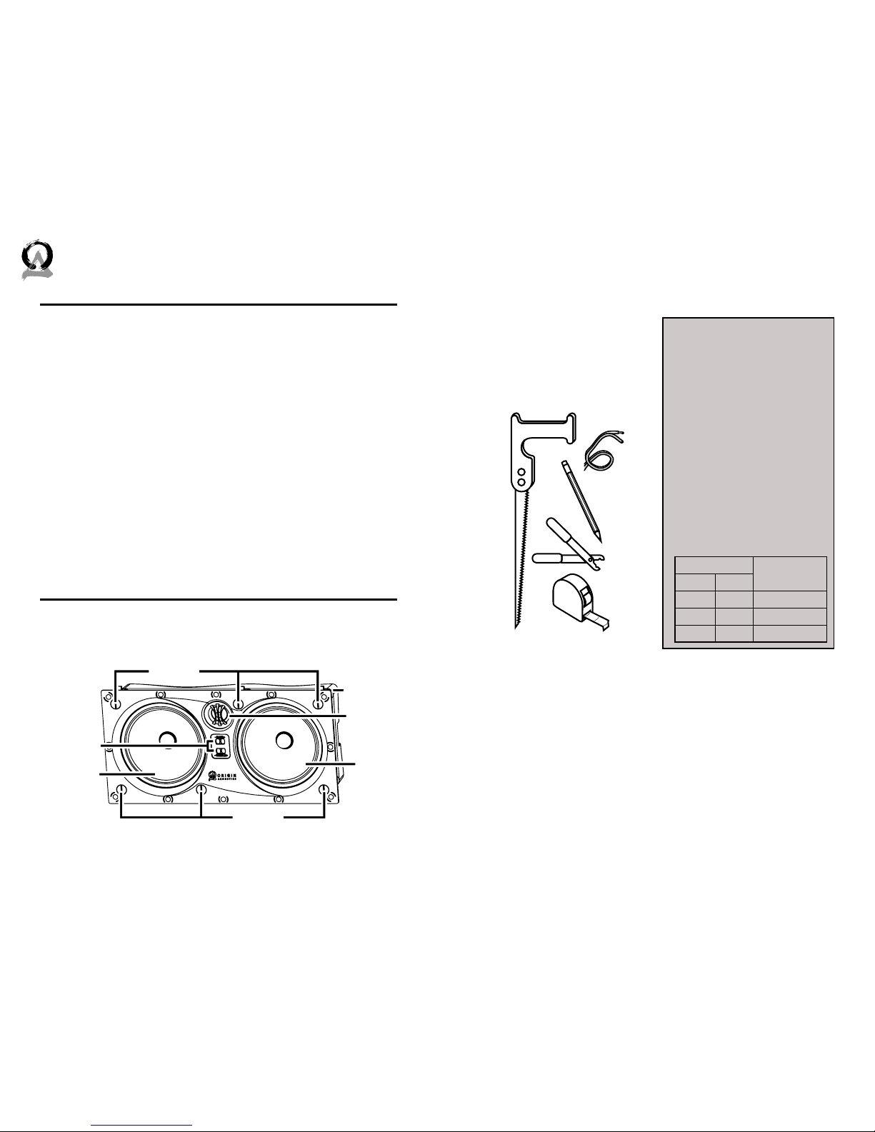
1) Installing the Wire
Strip ¼ to ½ inches (6 to 12
mm) of the insulation o both
ends of the wire. To avoid stray
strands, twist them at the end.
Connect the wire to the am-
plifier, and make sure the wire
connected to the le speaker
output will be routed to the le
speaker, right output to right
speaker, etc.
You will need a wire that has at least two conductors; one that can be
identified as the positive and the other as the negative. All two conductor
wires have some means of identifying which conductor is which, but at
times this identification may be subtle. It’s crucial that you keep track of
which wire you use for positive (+) and negative (-). Typically if the wires
are colored red and black, the red wire is used for positive and the black
wire is used for negative, but sometimes other colors or patterns are
used. You can choose whichever color of wire you want to be positive and
negative as long as you remain consistent throughout the install.
On both your amplifier and your speaker the connectors will be identi-
fied as red for positive and black for negative. It is very important to look
carefully at the speaker wires and be certain that the same wire that is
attached to the positive connector in the amplifier is attached to the pos-
itive connector in the speaker.
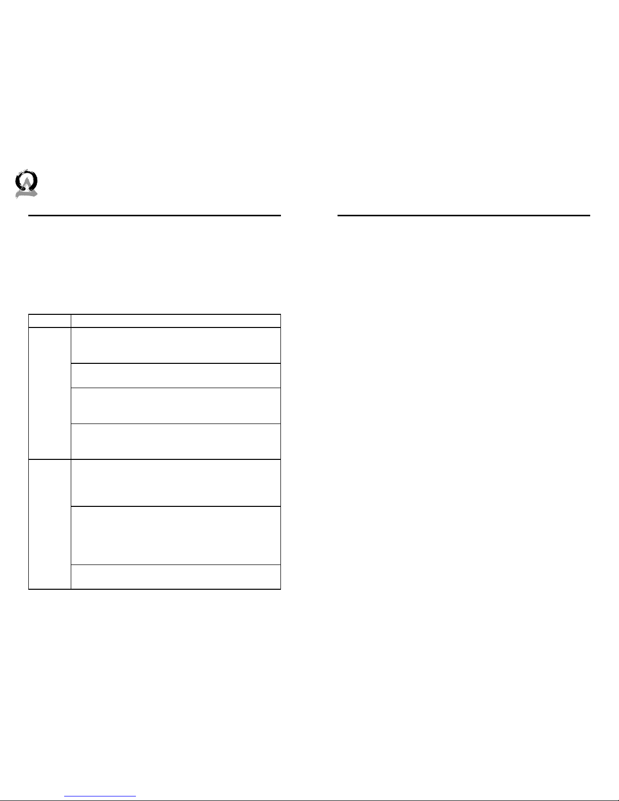
About Speaker Wire
Plan out how you’ll route the
wire to the desired speaker
location. There are several
methods for routing the wire,
and you will most likely need
to combine several of these
methods.
Under the Carpet:
One option is to li up the car-
pet and use tape wire to route
the wire under the carpet.
Behind the Baseboard:
If these speakers are being
installed in a new home during
construction, the installation
process will be a bit dierent (al-
though much simpler). For these
situations, it’s recommended
you purchase a bracket. In-
structions on how to install the
speakers are provided with the
bracket, or can be found on our
website. Visit www.originacous-
tics.com for more information.
For New Construction
Figure 6.1: Strip Wire
Figure 6.2: Twist Ends
The wire can be routed behind the baseboard by cutting a groove
out of the back of the baseboard, or by buying special baseboard
designed for concealing wires.
Through the Attic:
If the room is under the attic or a crawlspace, the wire can be rout-
ed through there.
Through the Basement:
Likewise, if there’s a basement or crawlspace under the floor, the
wire can be routed through there.
Route the wire through the walls and ceiling to the desired speak-
er location. Be sure to avoid all obstacles such as AC wiring, pipes,
and ducts.