Orion 21076 User manual

1
USER MANUAL / BRUKSANVISNING / MANUEL D’UTILISATION
Part No. / Art. Nr. / Réf.:
21076, 21077
AIR OPERATED OIL
DISPENSER 24L
LUFTDRIVEN
OLJEDISTRIBUTÖR
24L
DISTRIBUTEUR
D´HUILE
PNEUMATIQUE 24L

2
GENERAL / ALLMÄNT / GÉNÉRALITÉS
Pressurised unit for dispensing lubricants into motor crank cases. The
dispensing is produced through pressurising the unit. The compressed air
act on the lubricant inside the container, which is gradually dispensed when
the outlet oil control valve is opened.
Pre-load the container with compressed air 0,3-0,7 MPa (3-7 bar), and the
dispenser can be used without permanent connection to air pressure. Max.
admissible tank capacity is 3/4 of total capacity. Complete with 1,2 m hose
and oil control valve.
Trycksatt enhet för tappning av smörjoljor i oljetråg. Tappningen sker genom
att enheten trycksätts. Komprimerad luft trycker gradvis ut vätskan genom
utloppsventilen när denna öppnas.
Trycksätt behållaren med tryckluft 0,3-0,7 MPa (3-7 bar), och använd
utrustningen utan anslutning till tryckluft. Max.effektiv volym är c:a 18 liter.
Levereras med 1,2 m slang med oljeventil.
910 mm
GENERAL ALLMÄNT
EN
GÉNÉRALITÉS FR
SE
Ensemble pressurisé pour la distribution de lubriants des carters de
moteurs. Pour procéder à la distribution du lubriant, il est nécessaire
que le réservoir soit pressurisé avec de l’air en connectant une poignée
de gonage air à la soupape de charge. Le lubriant sera donc débité
graduellement en actionnant la poignée de distribution qui se trouve à la
sortie du réservoir.
Si l´on remplit le réservoir à l´avance d´air comprimé 0,3-0,7 MPa (3-7 bar),
on peut utiliser le distributeur sans branchementpermanent à l´air comprimé.
La capacité admissible max. du réservoir est le 3/4 de la capacité totale.
Complet avec un tuyau de 1,2 m et une vanne de contrôle d´huile.
300 mm 340 mm
B
E
F
F
A D

3
GENERAL / ALLMÄNT / GÉNÉRALITÉS
ATTENTION: Respect carefully the following operation and maintenance
security instructions.
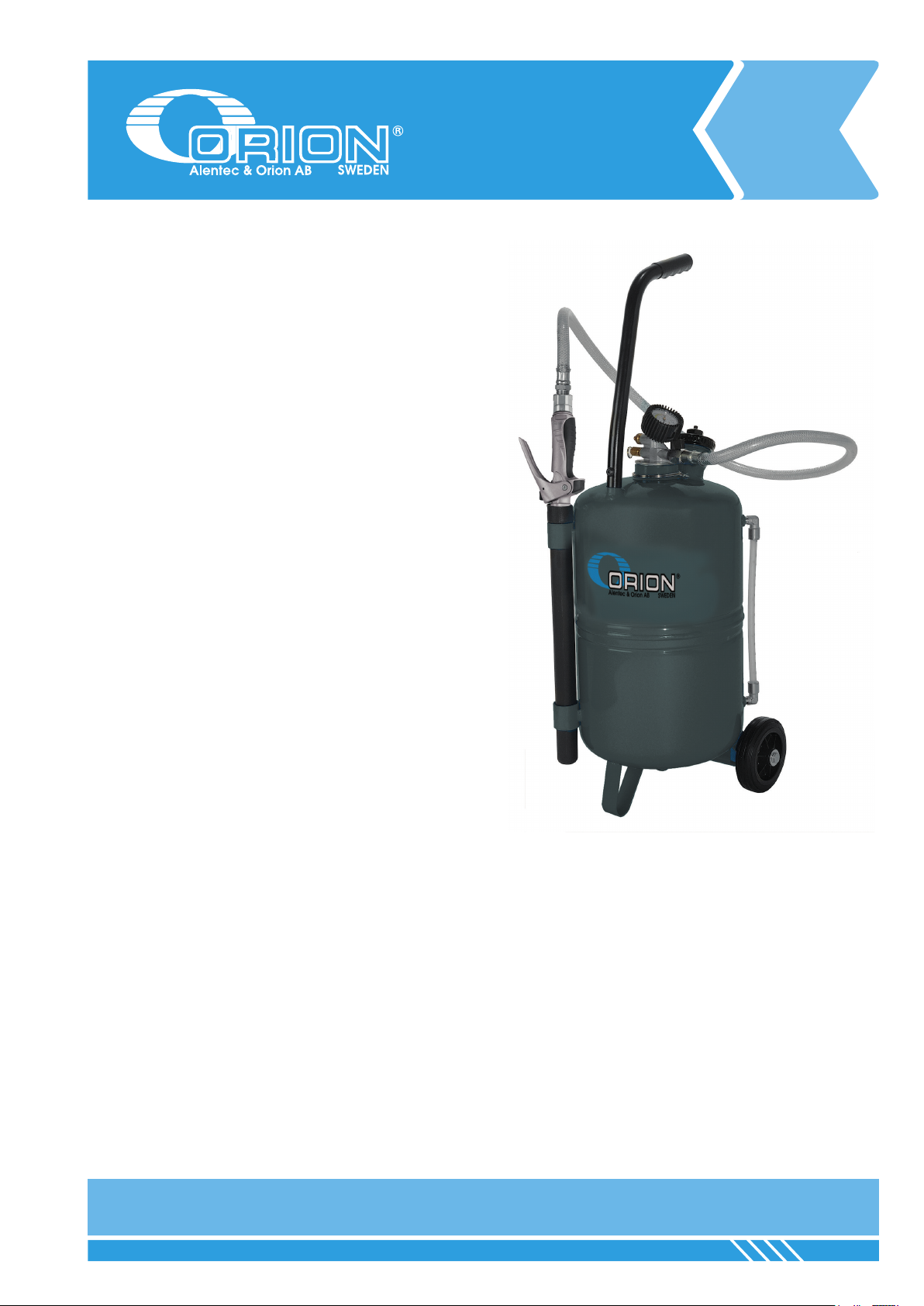
Filling the container:
WARNING: Do never unthread the 2” screw plug (A) unless the unit is
completely depressurised.
1. Unthread the 2” lid (A) situated on the bung opening, and ll in with
lubricant through this opening. Fill the unit between 18 and 20 litres of
lubricant. Thread back the 2” screw plug (A).
2. Verify that the shut-off valve (B), the control valve (C) are closed.
3. Pressurise the unit by connecting the compressed air line to the charge
valve (D). The unit must be pressurised at a maximum pressure of 7 bar. If
this pressure is exceeded, the unit is equipped with a security valve gauged
at 8 bar, which would let out the overpressure. To know the pressure inside
the container, the unit have a manometer (F).
4. Once the unit is pressurised, disconnect the compressed air line.
Dispensing the lubricant
To dispense the lubricant in the container, open rst the shut-off valve (B)
and the non-drip nozzle situated at the end of the outlet extension, before
opening the control valve (C). Use the unit until it is totally empty. DO NOT
PRESSURISE UNIT UNTIL IT IS RE-FILLED WITH 18/20 LITRES OF
LUBRICANT.
Emptying the unit (depressurisation)
WARNING: Do never unthread the 2” screw plug (A) unless the unit
is completely depressurised. To do this, just loosen the knurled plug of
the charge valve (D) and wait until the container is completely free from
pressure.
OBS: Följ dessa användnings-, säkerhets- samt underhållsinstruktioner
noga.
Fylla behållaren:
OBS! Skruva aldrig bort fyllningslocket utan att enheten är helt trycklös
1.Skruva bort fyllningslocket (A) och fyll på vätskan. Fyll på ca 18-20L
vätska. Skruva tillbaka locket. (A)
2. Säkerställ att avstängningsventilen (B), utloppsventil (C) är stängda.
3. Trycksätt enheten genom att ansluta tryckluft till laddningsventil (D).
Enheten får maximalt trycksättas med 7 bar. Om detta lufttryck överskrids,
kommer en säkerhetsventil släppa ut det övriga trycket vid 8 bar. För att se
hur mycket tryck som är i behållaren är den utrustad med en manometer
(F).
4. När enheten är trycksatt, koppla bort tryckluften.
Tappning av vätska
För att tappa vätska, öppna först avstängningsventilen (B) och non-
dripventilen på utloppsslangen på utloppsventilen.innan utloppsventilen (C)
öppnas. Använd enheten tills den är helt om. TRYCKSÄTT EJ ENHETEN
OM DEN INTE ÄR ÅTERFYLLD MED 18/20L VÄTSKA.
Göra enheten trycklös
OBS! Skruva aldrig bort fyllningslocket utan att enheten är helt trycklös.
Gör enheten trycklös genom att lossa på den räfade skruven på
laddningsventilen (D) och vänta tills enheten är helt trycklös.
GENERAL ALLMÄNT
EN SE
OPERATION / ANVÄNDNING / MODE D’EMPLOI
ATTENTION: Il est recommandé de respecter scrupuleusement les
instructions de sécurité qui vont suivre et qui concernent aussi bien le
fonctionnement habituel du produit que l’entretien de ce dernier.
Remplissage du distributeur
ATTENTION: Ne jamais desserrer le bouchon de 2’’ (A) sans avoir
complètement pressurisé le réservoir au préalable.
1. Desserrer le bouchon de 2’’ situé au niveau de la bouche de remplissage
(A). Verser le lubriant à cet endroit. La quantité de lubriant à remplir est de
18 à 20 litres. Serrer à nouveau le bouchon de 2’’ (A).
2. Vérier que la vanne (B), la poignée de contrôle (C) sont fermés.
3. Pressuriser l’appareil en branchant la ligne d’air comprimé à la soupape
de charge du distributeur (D). L’appareil doit être pressurisé à une pression
maximum de 8 bar. Ce dernier est également muni d’une soupape de
sécurité (E) permettant delaisser s’échapper la surpression au cas où la
pression maximum serait dépassée. Le distributeur est également muni d’un
manomètre (F) pour déterminer la pression intérieure du réservoir.
4. Déconnecter la ligne d’air comprimé dès que le réservoir est pressurisé.
Distribution du lubriant
Distribuer le lubriant stocké dans le réservoir à l’aide de la poignée de
contrôle de uide (C). Suivre les différentes instructions données jusqu’à
vider complètement le réservoir. NE SURTOUT PAS PRESSURISER TANT
QUE LE RÉSERVOIR NE SERA PAS REMPLI À NOUVEAU DE 18 À 20
LITRES LUBRIFIANT. Ouvrir au préalable la vanne (B) ainsi que le bec anti-
goutte situé à la n de l’extension de la poignée.
Vidange du distributeur
ATTENTION: Ne jamais desserrer le bouchon de remplissage (A) sans
avoir complètement pressurisé le réservoir au préalable. Pour cela il suft
de relâcher la soupape de charge (D) pour laisser s’échapper la pression
intérieure.
MODE D’EMPLOI FR

4
TROUBLE SHOOTING / FELSÖKNING / ANOMALIES ET SOLUTIONS
SYMPTOM POSSIBLE FAULT SOLUTION
The needle of the ma-
nometer does not move
during pressurising.
The manometer is broken.
Charge valve obstructed.
Replace the manometer.
Replace the charge valve.
Not possible to
pressurise the container. Charge valve obstructed. Replace the charge valve.
The needle of the mano-
meter exceeds 8 bar.
The manometer is malfunctioning.
Security valve malfunctioning.
Replace the manometer.
Replace the security valve.
No lubricant is dispen-
sed when the control
valve is opened.
Shut-off valve closed.
Low pressurisation.
Low lubricant level (only air comes out).
Open the valve.
Increase the pressure.
Fill in the container.
SYMPTOM TROLIG ORSAK ÅTGÄRD
Manometern rör sig inte
under trycksättning.
Manometern är trasig.
Laddningsventil är blockerad.
Byt ut manometer.
Byt ut laddningsventil.
Ej möjligt att trycksätta. Laddningsventil är blockerad. Byt ut laddningsventil.
Manometer indikerar
mer än 8 bar.
Manometern är trasig.
Säkerhetsventilen är trasig.
Byt ut manometer.
Byt ut säkerhetsventil.
Ingen vätska tappas när
utloppsventilen öppnas.
Avstängningsventil stängd.
Ej tillräckligt tryck.
Låg vätskenivå (kommer enbart luft).
Öppna avstängningsventilen.
Ladda behållaren med mer tryck.
Fyll på behållaren.
SYMPTOME CAUSES SOLUTIONS
L’aiguille du manomètre
reste immobile pendant
que le réservoir se
pressurise.
Le manomètre est abîmé.
La soupape de charge est bouchée.
Remplacer le manomètre.
Remplacer la soupape de charge.
Il est impossible de pres-
suriser le réservoir. La soupape de charge est bouchée. Remplacer la soupape de charge.
L’aiguille du manomètre
dépasse les 8 bar.
Le manomètre est en mauvais état, tout comme la
soupape de sécurité.
Remplacer le manomètre.
Remplacer la soupape de sécurité.
Le lubriant n’est pas
débité en actionnant la
poignée de distribution.
La vanne est fermée.
Le réservoir n’est pas complètement pressurisé.
Bas niveau de lubriant (il ne reste que de l’air).
Ouvrir la vanne.
Élever la pression.
Procéder au remplissage de lubriant.
EN
SE
FR

5
GENERAL / ALLMÄNT / GÉNÉRALITÉSSPARE PART KITS / RESERVDELSSATSER / KITS DE PIÈCES DE RECHANGE
EN SE FR
PART NO. CONSIST OF BESTÅR AV DÉSIGNATION POS. QUANTITY
/ ANTAL
24675 Oil control valve Oljeventil Pistolet à huile 17 1
2285473 Outlet extension Utloppsslang till oljeventil Tuyau de sortie 22 1
2395093 Lid Lock Bouchon du réservoir 31 1
2395092 Gasket for lid Packning till lock Joint de fermeture du bouchon 32 1
2315312 Manometer Manometer Manomètre 11 1
19
20
21
17
22
8
14
25
31
11
28
34
33
1 2 3 4
18
15
24
30
12
27
33
16
23
29
13
26
32
10
9
8
7
6
3
5

EC CONFORMITY DECLARATION / KONFORMITETSDEKLARATION /
DÉCLARATION CE DE CONFORMITÉ
Alentec&Orion AB, Grustagsvägen 4, SE-13840, Älta, Sweden, declares by the present certicate that the mentioned machinery is
in conformity with the following standards or other normative documents (TÜV S9211282), (DIN 24558 / 10.91),
(DIN EN 292 / 2/11.91) and has been declared in conformity with the EC Directive (2006/42/EEC).
Alentec&Orion AB, Grustagsvägen 4, SE-13840, Älta, Sverige, deklarerar genom detta certikat att de omnämnda utrustningarna
är i överensstämmelse med följande standarder eller normerande dokument (TÜV S9211282), (DIN 24558 / 10.91), (DIN EN 292 /
2/11.91) och har blivit deklarerade i enlighet med EC Direktiv (2006/42/EEC).
Alentec & Orion AB, Grustagsvägen 4, SE-13840, Älta, SUÈDE, déclare par ce certicat que les pompes mentionnées sont con-
formes avec les standards suivants ou autres documents normatifs (TÜV S9211282), (DIN 24558 / 10.91), (DIN EN 292 / 2/11.91) et
ont été déclarés en conformité avec la Directive EC Direktiv (2006/42/EEC).
Krister Tynhage
Managing Director
Mikael Theorin
Technical Director
EN
SE
FR
This manual suits for next models
1
Popular Dispenser manuals by other brands

BOWMAN
BOWMAN BD637-0012 quick start guide

Ugolini
Ugolini Deluxe 12L UL Operator's manual

Server
Server Express Direct-Pour SE-SS-DP manual

Newco
Newco NHW-15 operating manual

NORDWEST
NORDWEST PROMAT SD006 user manual

APW Wyott
APW Wyott CCW MK VII, RCCW MK VII, LCCW MK VII, RLCCW MK... Installation and operating instructions

Georgia Pacific
Georgia Pacific GP PRO Dixie Ultra SmartStock Tri-Tower Mounting instructions

Nordson EFD
Nordson EFD HP Series user guide

DS Produkte
DS Produkte TV0086 operating instructions

Betec
Betec Aquarius Mini WD 4000 Instructions for use

Loctite
Loctite HD10 instructions

Cornelius
Cornelius Millennium II 6000 installation manual