Orno OR-ZS-805 User manual

Self-Contained
Access Control Reader
AR-2808
User Manual
AEI
PROTECT-ON
SYSTEMS
LIMITED
www.apo-hk.com VERSION: 01/2015
FCC STATEMENT
Caution:
Any changes or modifications not expressly approved by the party responsible for compliance could void the user’s authority to operate
this equipment.
This device complies with Part 15 of the FCC Rules. Operation is subject to the following two conditions:
(1) This device may not cause harmful interference, and
(2) this device must accept any interference received, including interference that may cause undesired operation.
This device and its antenna(s) must not be co-located or operating in conjunction with any other antenna or transmitter.
NOTE:
This equipment has been tested and found to comply with the limits for a Class B digital device, pursuant to Part 15 of the FCC
Rules. These limits are designed to provide reasonable protection against harmful interference in a residential installation. This
equipment generates, uses and can radiate radio frequency energy and, if not installed and used in accordance with the instructions,
may cause harmful interference to radio communications. However, there is no guarantee that interference will not occur in a
particular installation.
If this equipment does cause harmful interference to radio or television reception, which can be determined by turning the equipment off
and on, the user is encouraged to try to correct the interference by one or more of the following measures:
-- Reorient or relocate the receiving antenna.
-- Increase the separation between the equipment and receiver.
-- Connect the equipment into an outlet on a circuit different from that to which the receiver is connected.
-- Consult the dealer or an experienced radio/TV technician for help.
OR-ZS-805

TABLE OF CONTENTS
INTRODUCTION
SPECIFICATIONS
Package Contents
THE FRONT PANEL
Status Indicator (Blue)
Operation Indicators
Card Reader Window
Door Bell Button (Function Selector)
INSTALLATION
Precautions for Installation Location
Precautions for Accidental Short Circuit
Precautions for Electric Spikes & Back EMF
THE CONNECTION TERMINALS
1 - 2 : 12VDC (Power Input Terminal)
3 : (+) 12V Power Supply for The Lock
4 : (-) Power Supply for The Lock (Output Contact for Door Lock Strike)
5 : EG IN (Egress Input for N.O. Button)
6 : Data I/O Port
7 - 8 : Door Bell (Relay Contact for Optional Door Chime)
9 - 10 : Tamper Switch (Tamper Switch with N.C. Contact)
CREATE A MASTER CARD (CMC)
The First Step before Programming - Make A Madter Card
Procedures of Creating A New Master Card with CMC Jumper
PROGRAMMING
1) Criteria for Setting System to Programming Mode
2) Use The Master Card to Set System into Programming Mode for The 5 Feature Groups
3) The Reading Manner for Master Card
4) Audible Indications in Programming & Operation
I ) RECORD USER CARD(S) – Feature Group 1
II ) DELETE USER CARD(S) – Feature Group 2
III ) SET OUTPUT MODE FOR DOOR LOCK -- Feature Group 3
IV ) SET SYSTEM SAFETY LOCK-UP -- Feature Group 4
V ) CREATE / DELETE SUPER USER CARD(S) -- Feature Group 5
OPERATION
FEATURE SETTING PROCEDURES SUMMARY CHART
APPLICATION EXAMPLES
1) Stand Alone Access Control Electric Lock
2) Application Hints for The Auxiliary Terminals
APPLICATION EXPANSION – The Optional Auxiliary Reader AR-2802
Multi- Station Access Control Electric Lock
...................................................................................................................... 3
................................................................................................................... 3
................................................................................................................ 3
................................................................................................................ 4
.......................................................................................................... 4
............................................................................................................. 4
............................................................................................................ 4
...................................................................................... 4
........................................................................................................................ 5
...................................................................................... 5
................................................................................ 5
.......................................................................... 5
............................................................................................. 6
.................................................................................... 6
.................................................................................. 6
................................ 6
................................................................................ 7
..................................................................................................................... 7
..................................................... 7
.................................................... 7
.......................................................................................... 8
.................................................... 8
.............................................. 8
....................................................................................................................... 9
............................................................... 9
.. 9
................................................................................. 9
................................................................ 9
................................................................... 10
.............................................................. 11-12
........................................... 13
...................................................... 14
................................. 15-16
.............................................................................................................................. 17
................................................. 18-19
..................................................................................................... 20
......................................................................... 20
..................................................................... 20
............................. 21
............................................................................ 22
2
SPECIFICATIONS
INTRODUCTION
3
AR-2808 is a self-contained access control reader designed to drive electric door lock directly. It
accommodates up to 500 proximity EM cards and its output is compatible with the Fail-safe and
Fail-secure electric locks. The door lock striking time is programmable. A built-in door chime relay
contact is also available to operate an external low power door chime. It is a full feature compact
reader ideally for the access control system in small office and home applications. The system
employs solid state switch instead of relay contact for door lock strike. It gives longer service life and
prevents the sabotage of opening the door with strong magnet.
AR-2808 is built-in with Data I/O bus for system expansion. Maximum three optional card readers
(AR-2802) can be connected with it to make a multi-station access control system.
● Operation Voltage: 12VDC Nominal, 11-16VDC
● Operating Current: 60mA (quiescent), 80mA Maximum
● Storage & Operation Temperature: -20°C to +70°C
● Storage & Operation Humidity: 5-95% Relative Humidity, Non-condensing
● Working Environment & Ingress Protection: Indoor or Outdoor, IP-55 Weatherproof
● Number of User Cards: 500, Standard 125Khz Proximity EM Cards or Keyfobs
● Number of Super User Cards: 5, Standard 125Khz Proximity EM Cards or Keyfobs
● Safety Lock-ups: a) No Lock-up, b) Auto Lock-up after Invalid Trials, & c) Manual Lock-up with
iiiiSuper User Card
● Door Lock Operating Timer: 1-60 Seconds Programmable
● Egress Button: Normally Open (N.O.) Button(s) for Request to Exit from Inside
● Data I/O Bus for Optional Card Readers (AR-2802). Accommodates 3 Optional Readers Max.
● Bell Button: Output Relay Contact for Actuating An Optional Door Chime
● Output Contact Ratings:
iiiia) Solid State Output for Lock Strike – Fail-safe or Fail-secure Selectable, 3A/16VDC Max.
iiiib) Door Chime Relay – N.O. Dry Contact, 1A/24VDC Maximum
iiiic) Tamper Switch – N.C. Dry Contact, 50mA/16VDC Maximum
● Dimensions: 60(W) X 119(H) X 23(D) mm
● Weight: 160g Net
● Housing: ABS Plastic
Specifications are subject to change for modification without notice
PACKAGE CONTENTS
●One AR-2808 Reader
●Two EM Cards
●One Pack of Mounting Screws
●One Hex Socket Screw Wrench
●One User Manual
Description
The AR-2808 is expandable to a multi-station system for user convenience with the auxiliary
reader AR-2802. Maximum 3 AR-2802 can be connected in parallel with the Data I/O Bus of
the AR-2808. The auxiliary reader(s) reads the Cards as like the master reader AR-2808
which is the server of the system to manage the data from the auxiliary reader(s).
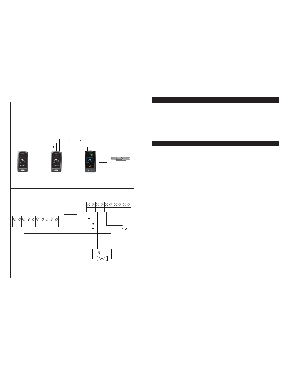
Multi- Station Access Control Electric Lock
ELECTRIC
LOCK
AR-2808
THE SERVER
AR-2802
AUXILIARY
READER
AR-2802
AUXILIARY
READER
DATA I/O BUS
( +) POWER SUPPLY
COMMON( –) GND
Wiring Diagram
AR-2802 AUXILIARY READER (S)
10987654321
RS232BUZ
LED D1
D0
DATA
I/O
TAMPER
N.C.
( + ) ( – )
12VDC
AR-2808 MASTER READER (THE SERVER)
10987654321
TAMPER
N.C.
DOOR BELL
N.O.
( + ) ( – )
DOOR LOCK
( + ) ( – )
12VDC
DATA
I/O
EG
IN
12VDC
POWER
SUPPLY
ELECTRIC
LOCK
*JUMPER SELECTION
FOR ELECTRIC LOCK OF
(1) FAIL-SAFE OR
(2) FAIL-SECURE
( + )
( – )
EGRESS
BUTTON
N.O.
DATA I/O BUS
( + )
( – )
( + ) ( – )
1N4004
System Connection
COMMON GND
More AR-2802 can be connected in parallel.
22
OR-ZS-805
OR-ZS-805
OR-ZS-805. OR-ZS-805
Maximum 3 auxiliary readers
OR-ZS-805
OR-ZS-805
OR-ZS-805
4
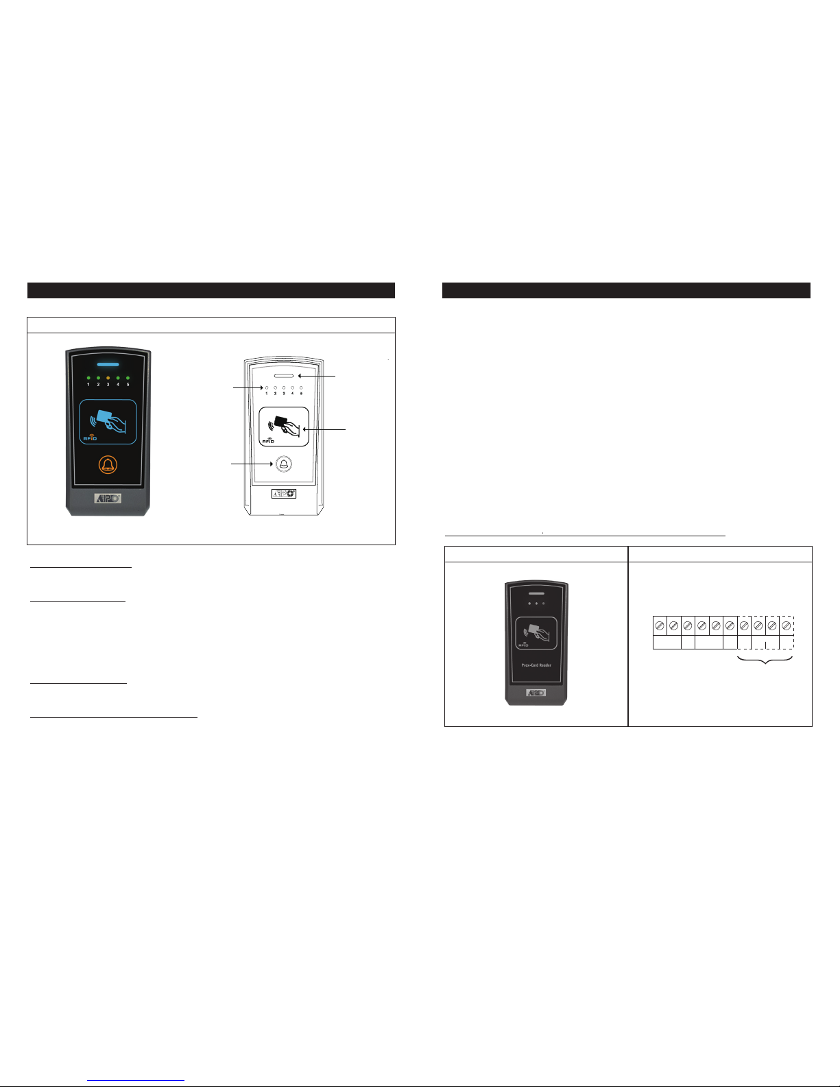
THE FRONT PANEL
Status Indicator (Blue)
It is ON in normal operation. It flashes during programming mode or lock-up mode.
Operation Indicators
The 5 LED indicators with number 1, 2 ,4 and 5 in green and number 3 in amber color show the
status of the system in Operation Mode or in Programming Mode.
1) They indicate the Storage Group of an EM card when it is read in Operation Mode.
2) They show the status of feature settings in Programming Mode. See “Programming” &
“Operation” sections for the details.
Card Reader Window
It is a place for reading EM cards.
Door Bell Button (Function Selector)
This button has two functions. It is a door bell button in normally operation and is a function
selector in programming mode. See the details in “Programming” & “Operation” sections.
●
●
●
●
AR2808 FRONT PANEL
Status Indicator
(Blue)
Card Reader
Window
Operation Indicator
Door Bell Button
(Function Selector)
21
APPLICATION EXPANSION – The Optional Auxiliary Reader AR-2802
Apart from standard-alone operation, AR-2808 is expandable to be a Multi-station System with the
optional auxiliary reader AR-2802. Maximum three optional readers can be allowed and the
connection is very simple. Just connect the devices in parallel with the Data I/O Bus of the
AR-2808. The AR-2808 acts as a server of the system and manages the data among them.
A Multi-station System provides higher security in access control and user convenience to operate
an electric lock at different locations. Such as a dual reader system for area needs controlling of
going in and going out with proximity EM cards.
The optional reader is available in standard version (AR-2802S) and advanced version
(AR-2802A). The advanced version also provides Wiegand and RS-232 data outputs for custom
project development with access control panel and / or PC.
The AR-2802 is also compatible with all the Tri-Tech keypads in the 2nd generation DK-2800
series for system expansion.
*Please contact your local agent for the optional reader if system expansion is required.
The Auxiliary Reader AR-2802 And It’s Connection Terminals
Connection TerminalsAuxiliary Reader
10987654321
LED
DATA
I/O
TAMPER
N.C.
( + ) ( – )
12-24V DC
WIEGAND
D0 D1
BUZ RS
232
AR-2802A ONLY
OR-ZS-805
OR-ZS-805 OR-ZS-805
5
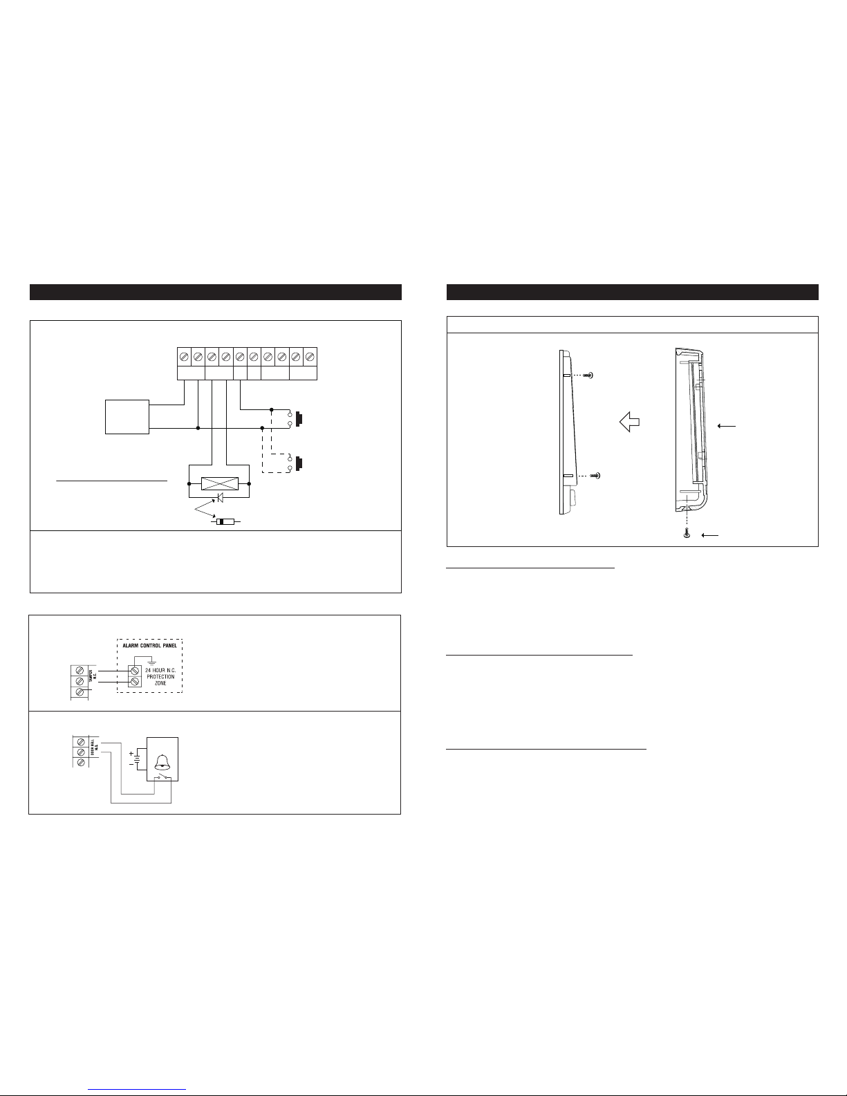
INSTALLATION
AR-2808 ASSEMBLY
Precautions for Installation Location
The EM Card works at the frequency of 125Khz. Installation precautions are necessary:
Fi) Make sure the location has no strong low frequency electro-magnetic wave signals near it.
IIIIIIEspecially in the range of 100-200Khz.
Fii) If more than one keypads / readers operating in the same frequency, make sure that they are at
IIIIIIleast 60cm (2ft) apart from each other. Otherwise, the reading range may be reduced due to
IIIIIIinterference.
Precautions for Accidental Short Circuit
In the previous experience, most of the damages caused during installation are accidental touch of
the components on the circuit board with the wire(s) carrying power. The following precautions are
necessary:
Fi) Study the manual thoroughly to become familiar with the system before installation.
Fii) Do Not apply power to any connection terminal of the reader during installation.
Fiii) Check all the wirings carefully and confirm that they are correct before applying power to the
F13Ireader for testing.
Precautions for Electric Spikes & Back EMF
Make sure to connect the diode (supplied) or a varistor (MOV) across the electric lock’s power input
terminals to absorb the back EMF and the electric spikes. Fail to do so may cause damage to the
electronic components; in worst case, even burn out the reader.
FRONT COVER
BACK COVER
(Fix it on wall)
HEX SOCKET SCREW
20
1) Stand Alone Access Control Electric Lock
NOTE:
● Connect the 1N4004 as close as possible to the lock in parallel with the power terminals of the lock to absorb
....the back EMF to prevent it from damaging the reader. The 1N4004 is not required if the electric lock is AC
....operated.
● To aviod Electro-Static-Discharge from interfering with the operation of the reader, always ground the (-) terminal
... 2 to earth.
APPLICATION EXAMPLES
* See Door Lock Selection Jumper
1.SAFE -- For Fail-Safe Electric Lock
2.SECURE -- For Fail-Secure Electric Lock
10987654321
EG
IN
DATA
I/O
DOOR BELL
N.O.
TAMPER
N.C.
( + ) ( – )
DOOR LOCK
( + ) ( – )
12VDC
12 VDC
POWER
SUPPLY
ELECTRIC LOCK
( – )( + )
*
AP-960
AD-2312
AD-2322 ( – )
( + )
AR-2808
N.O.
N.O. MORE EGRESS BUTTONS CAN
BE CONNECTED IN PARALLEL
EGRESS BUTTON
(INSIDE HOUSE)
CATHODE
IN4004
The tamper switch is Normally Closed while the
reader is secured on box. It is open when the
reader is removed from box. To give alert on
sabotage, connect these terminals in series with a
24 hour N.C. protection zone of an alarm system if
required.
10
98
(A) TAMPER N.C.
(B) DOOR BELL N.O.
ELECTRONIC
DOOR CHIME
(OPTIONAL)
N.O.
DOOR
BELL
8
7
6
The connection of the Door Bell is optional. The
door bell contact on the keypad is prepared for
triggering of an low power door chime only. DO NOT
use it as a high voltage power path for a door bell.
The maximum power rating of the contact is 24V
DC/1 Amp.
2) Application Hints for The Auxiliary Terminals
Table of contents


