3
Qo
E
70
×Pceff ×P
Pa
×G×q(coulombs)(1)
4. OPERATION
Once the steps outlined in Section 3 of this manual
are performed, the unit is ready for use. High
voltage may be applied and adjusted for the
appropriate gain associated with the specific
experiment. The gain will vary by a factor of
approximately 2 for each high-voltage change of
100 V. NOTE: It is advisable to operate the high
voltage at the minimum practical value when the
high count rates are to be experienced, since count
rate tolerance is a direct function of the
photomultiplier gain.
4.1. CALCULATION OF RESPONSE OF
SCINTILLATOR/PHOTOMULTIPLIER
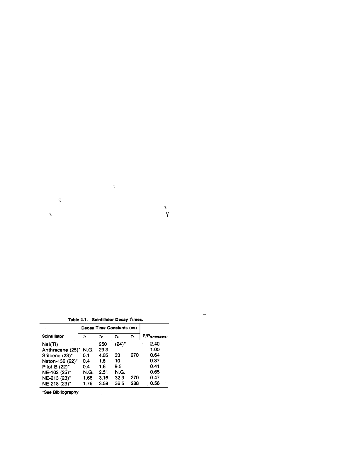
Table 4.1 lists the decay constants of some of the
more common scintillators. The first three
scintillators are crystals. Naton-136, Pilot B, and
NE-102 are plastics, and the last two are liquid
scintillators. The decay time 1is responsible for a
finite rise time on the leading edge of L(t) (refs. 12,
21, 22); 2is the fast decay component which is mot
noticeable at the output of the photomultiplier; 3
and 4are the slow components (important for n-
discrimination with NE-213, NE-218, and Stilbene).
Where measured values were not given, the letters
N.G. have been entered. The parameter P is the
number of photo electrons released at the
photocathode per unit energy. This figure is
affected by the efficiency and spectral response of
the photocathode (refs. 22, 23, 26, 27) and hence
is somewhat characteristic of the photomultiplier
used. However, it provides a reasonably good
guide for comparing the light output of scintillators.
In Table 4.1, P is listed as a fraction of the value for
anthracene; P(anthracene) is ~700 eV/ photoelectron for
S-11 photocathode material.
The thickness of the scintillator is frequently chosen
according to the required stopping power. The flight
time of the radiation (gamma rays or neutrons)
across the scintillator normally becomes a limitation
on the time resolution as the thickness is increased.
Usually detection efficiency must be compromised
for good time resolution.
The scintillator geometry and the coupling to the
phototube must be carefully considered: If the light
can travel a variety of path lengths before being
collected, an additional contribution to the time
resolution will result. Light collection is widely
discussed in the literature (refs. 15, 17–19, 28, 29).
Table 4.2 lists the characteristics of several types of
photomultipliers. It is noteworthy to observe that the
gain of theses tubes ranges from ~0.5 ×10⁶to 2.5
×106. This gain is strongly affected by the age of
the tube and the temperature and will change by a
factor of ~2 for each 100-V change in high voltage.
For response calculations there are several
approximations that will aid in a quick “ballpark”
answer:
1. Conversion for absorbed energy (eV) to
photons (p) for anthracene is ~70 eV/p (ref. 35).
2. Conversion of photons to photoelectrons for
S-11 photocathode material is ~10% (ref. 37).
3. 100% of photons are collected on the
photocathode and 100% of cathode-emitted
photoelectrons are collected on the first dynode.
The function for the total charge output now
becomes
where
Qo= output charge in coulombs
E = absorbed energy in detector in eV
P/Pa = detector efficiency compared to
anthracene from Table 4.1
G=photomultipliergainfromTable4.2or
from manufacturer’s data
q=chargeperelectron1.6×10-19
coulomb
Pceff = efficiency of photocathode or ~10% for
S-11.