Ortlinghaus TPI 215 EN Operation manual

Ortlinghaus-Werke GmbH
Postfach 50 14 40
42907 Wermelskirchen
Kenkhauser Str. 125
42929 Wermelskirchen
Germany
Tel. +49 2196 85-0
Fax +49 2196 855-444
Email [email protected]
Website www.ortlinghaus.com
Version: 03.2012
450 series
Keep for future use
Translation of
original operating manual
Technical product information
TPI 215 EN
Pneumatically released
brake

Ortlinghaus-Werke GmbH Operating instructions TPI 215 EN
2 03.2012
Table of contents
1. Notes regarding use of the operating manual 3
1.1. Who are the operating instructions aimed at? 3
1.2. What can be found in the operating instructions? 4
1.3. Use of these instructions 4
1.4. Notes on the symbols used in the text 4
1.4.1. Personal injury 4
1.4.2. Product / machinery / plant system damage 5
1.5. Personnel qualifications and training 5
1.6. The Ortlinghaus numbering system 5
2. Technical data / intended purpose 6
2.1. Intended Use 6
2.2. Appropriate use 6
2.3. Improper use 7
2.4. Functional description 8
2.4.1. Braking 8
2.4.2. Engaging the clutch (optional version) 8
2.5. Variants 9
2.5.1. Different ways in which the plates are
suspended 9
2.5.2. Different friction linings 9
2.5.3. Special versions 9
3. Transport, packaging 10
3.1. Hazard notes on transport, packaging 10
3.2. Condition on delivery 10
3.3. Transport 11
4. Installation and assembly instructions 12
4.1. Installation conditions 12
4.2. Fundamental installation variants 13
4.3. Installation with twelve-point suspension of
the plates 13
4.4. Installation with twelve-point housing plate
mounting (friction block version) 14
4.5. Installation with two-point plate suspension 15
4.6. Installation with combined suspension of the
plates 15
5. Commissioning 16
5.1. Hazard notes on commissioning 16
5.2. Function test 18
6. Operation 19
6.1. Hazard notes for operation 19
6.2. Inspection while the machine is in operation 21
6.3. Setting the oiler 21
7. Troubleshooting 22
8. Maintenance 24
8.1. Hazard notes on maintenance 24
8.2. Checking wear by measuring the air gap 25
8.3. Wear compensation at friction lining half-
wear point (from size 61 and upwards)) 26
8.3.1. Setting of the wear indicator (with reduced
cylinder volume) 27
8.4. Removing and fitting the plates/housing plates 27
8.4.1. Twelve-point suspension of the plate 28
8.4.2. Twelve-point suspension of the housing
plates (friction block version) 28
8.4.3. Two-point suspension of the plates 28
8.5. Maintenance intervals 28
8.5.1. Changing the seals (elastomer) 29
8.5.2. Changing the springs 29
8.6. Care 29
9. Servicing and repair, modification 30
9.1. Hazard notes on servicing and repairs 30
9.2. Dismantling of the brake 31
9.3. Assembly of the dismantled brake 32
9.4. Hazard notes on modification 34
10. Spare parts 35
10.1. Spare parts list for brake 0450- . . . -23- 36
10.2. Isometric diagram for brake 0450-...-23- 37
10.3. Replacement parts list for brake 0450-...-
29- to 0450-...-61- 38
10.4. Isometric diagram for brake 0450-...-29- to
0450-...-61- 39
10.5. Replacement parts list for brake 0450-...-
62- to 0450-...-93- 40
10.6. Isometric diagram for brake 0450-...-62- to
0450-...-93- 41
11. Storage, de-commissioning 42
11.1. Hazard notes on storage, de-commissioning 42
11.2. Storage 43
11.3. De-commissioning 43
12. Disposal 44
12.1. Hazard notes on disposal 44
13. Annex 45
13.1. Declaration of Conformity 45
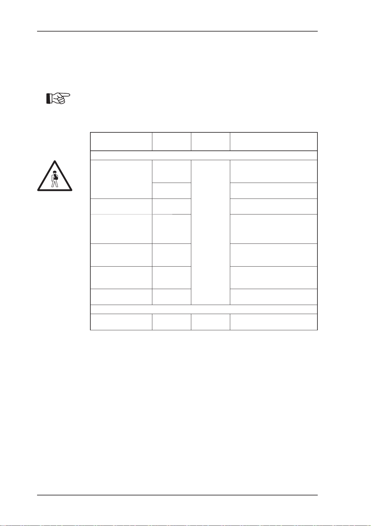
Table 1: List of amendments
Amendment Edition date
BA rev. no. 215.002 03.2012

Ortlinghaus-Werke GmbH Operating instructions TPI 215 EN
03.2012 3
1. Notes regarding use of the operating manual
These operating instructions, hereafter referred to as OI, are part of the
product and contain important information on how to safely and correctly
operate our product in machinery and plant systems as well as maintain,
repair, convert, store, decommission and dispose of the product.
In addition to these OI please also refer to the technical descriptions and
information provided in the product drawing as well as the application-
specific design data, e.g. design calculations. If these should not be
contained within the scope of documentation then please request these
immediately from Ortlinghaus.
Without the product drawing these OI are incomplete.
Keep these OI in a safe place, make them accessible to all users at all
times and pass them on to your customers! If necessary, you can down-
load our OI or TPI via the internet from the “Service” directory at www.
ortlinghaus.com. You are also free to make copies of this example. Always
keep the OI near to the machine or system in order to ensure direct acces-
sibility.
On delivery of the product, the attached OI represent the latest technical
development at the time of publication. Any supplements provided by us
should be added to the OI by you or future owners.
We reserve the right to make technical changes to these OI as part of tech-
nical further development. Please ensure that you have the most recent
version of the information.
This information can be requested by telephone (for telephone number see
front page) and obtained in text form or downloaded from the internet at
www.ortlinghaus.com under “Download”.
1.1. Who are the operating instructions aimed at?
These OI are aimed at qualified specialist personnel, especially:
➜assembly fitters of the machinery/plant system manufacturer;
➜industrial mechanics/fitters of the machinery operator;
➜other qualified and properly trained specialist personnel, responsible for
and thereby entrusted with project planning, assembly, commissioning,
operation, maintenance, decommissioning, storage and disposal of the
product.
Persons tasked with using the product must read the OI carefully before
conducting any work. If these prerequisites are not fulfilled, there is a risk
of the product being used incorrectly with severe damage to the product
and subsequent damage to other items as well as physical or fatal injury
and health hazards to the user or third parties. Reference is made in addi-
tion to paragraph 1.5 of the OI.

Ortlinghaus-Werke GmbH Operating instructions TPI 215 EN
4 03.2012
1.3. Use of these instructions
➜Read through these OI completely before working with the product.
➜The instructions in the OI must be complied with.
➜Consider the product drawing as well as any design calculations.
➜These OI are part of the product and should be kept accessible for all
users.
➜If the product is passed on to a third party then pass these OI on as
well.
1.2. What can be found in the operating instructions?
These OI with the product drawing contain all the necessary information
related to the product named on the cover page for the proper utilisation
throughout the various stages of operation.
Note the residual dangers and safety information provided for the stages
of operation.
1.4. Notes on the symbols used in the text
Our products are produced in accordance with our knowledge of latest
engineering practice at the time of design and are operationally safe
and are subject to constant product enhancement. Nonetheless there is
a danger to personnel and property if the following instructions are not
complied with. For hazard-free installation, function and operation the most
important passages in the following pages are highlighted with symbols.
These symbols mean:
NOTE!
➜Pay special attention to this text.
1.4.1. Personal injury
WARNING!
• Hazard while performing the described activity or as a result of hazards
during machine operation.
➜Potentially severe head injury.
WARNING!
• Hazard while performing the described activity or as a result of
hazardous electrical voltage during machine operation.
➜Potentially severe head injury.
ATTENTION!
• Hazard while performing the described activity or as a result of hazards
during machine operation.
➜Potential physical injury or risk to health.

Ortlinghaus-Werke GmbH Operating instructions TPI 215 EN
03.2012 5
1.5. Personnel qualifications and training
Work on our products may only be carried out by professionals (authorized
persons) who possess appropriate qualification or professional training
pertaining to the tasks to be carried out, and who acknowledge and under-
stand the content of these OI.
Professional personnel (authorized persons) must acknowledge and observe
the applicable safety standards.They must use appropriate safety equip-
ment. Furthermore, professional personnel (authorized persons) must be
able to detect possible hazards that could arise in the course of carrying out
their work.
The level of responsibility, expertise, qualification and monitoring of profes-
sional personnel (authorized persons) is the responsibility of the operator.
If personnel do not possess the requisite qualifications and knowledge then
they must be trained and instructed accordingly.
1.6. The Ortlinghaus numbering system
Example: 0 111 - 222 - 33 - 444 555
0 = Code digit for products
Code digits for series
Code digits for design characteristics
Design size
Serial no.
Further design characteristics
WARNING!
• Hazard while performing the described activity or as a result of non-
observance of explosion protection during machine operation.
➜Potentially severe head injury.
1.4.2. Product / machinery / plant system damage
CAUTION!
• Hazard while performing the described activity or as a result of mechan-
ical hazards during machine operation.
➜Potential material damage.
Non-observance of safety notices results in a loss of any claim for
compensation.

Ortlinghaus-Werke GmbH Operating instructions TPI 215 EN
6 03.2012
2. Technical data / intended purpose
2.1. Intended Use
The pneumatically released spring pressure brakes are suitable for appli-
cations with high torques and high heat loading, e.g. for slowing large iner-
tial masses. They find application above all in presses and shearing units.
WARNING!
• The brakes should not be used in atmospheres with high humidity or
which contain oil.
➜Otherwise, there is the danger of the plates slipping, causing braking
action to deteriorate significantly.
2.2. Appropriate use
Our products are intended exclusively for use in accordance with the tech-
nical data stipulated per the design shown on the product drawing
(0 . . . - . . . - . . - . . . . . .)
The order-specific design which was performed by Ortlinghaus may only
be used for the intended application.
The technical data specified by the customer is a component of the
intended use. Insofar as a specification sheet which has been approved by
both sides is present, it is also essential. The customer is responsible for
the correctness of its data.
Our product is intended to be integrated into a system or machine or to be
assembled with other components to form a system or machine. For this
reason, the product should only be brought into circulation once the system
or machine into which the product is to be integrated has completely
fulfilled the applicable EU machinery directive.
Intended use also includes complying with the directions given in this oper-
ating manual, and paying attention to any residual dangers. Remaining
hazards are described in the hazard warning sections of the following
chapters. During the various applications (operating stages) in which
damage to the machine or hazards to personnel can arise, the operator
must ensure that appropriate safety measures are applied. Observe the
applicable national regulations pertaining to accident prevention and envi-
ronmental protection.

Ortlinghaus-Werke GmbH Operating instructions TPI 215 EN
03.2012 7
2.3. Improper use
Any other use or use going beyond the use described in the chapter
“Intended purpose” and “Proper use” is considered to be improper use.
Ortlinghaus is not liable for damages arising from this.
In particular, but not exclusively, our product is considered to be subjected
to improper use if it:
➜is used as a bearing in the sense of supporting and guiding moving
machine parts with respect to the stationary part
➜is overloaded by an excessive speed, an excessive torque during
braking or by an excessive operating pressure (also briefly by pressure
peaks)
➜is overloaded by excessively long sliding actions on the friction surfaces
(e.g. by overloading)
➜is operated with insufficient cooling or with an operating pressure that is
too low
➜is loaded by an excessively high switching frequency e.g. in activation
mode
➜is brought into service with contaminated or oily friction linings
➜is operated with an excessive quantity of oil in the compressed air
NOTE!
➜If the safety instructions and residual hazards are not observed then this
is also considered improper use.
WARNING!
• Unauthorised conversions and modifications on the product are not
permitted for reasons of safety.
➜Modifications to or on our products are prohibited. Where this is not
observed, any claims made against Ortlinghaus-Werke GmbH will be
deemed void.

Ortlinghaus-Werke GmbH Operating instructions TPI 215 EN
8 03.2012
2.4. Functional description
ATTENTION!
• The normal operating pressure is 5.5 bar
• The maximum permissible pressure 6 bar
➜Never operate the brake at a higher pressure due to the risk of cylinder
breakage.
NOTE!
➜Always use dust-free, dry compressed air (a maintenance unit is
required).
➜Set the oiler of your maintenance unit so that it delivers from 1 to
3 drops of oil per m3air.
➜It is essential that the friction linings are kept free of oil.
2.4.1. Braking
Pressure springs 4press against piston 3in the cylinder. This causes
brake plate 2to be pressed against the stop plate, thus bringing about the
braking action. If the piston 3is acted on with the required operating pres-
sure via the air feeds 5, then the brake plate 2is released and the brake is
disengaged.
2.4.2. Engaging the clutch (optional version)
The brake of the model series 450 can optionally be used as a spring-
loaded clutch. By replacing the brake plate 2with a clutch plate enables a
spring-loaded clutching.
The piston (3) is pressurised with compressed air via the air feeds (5). This
disengages the clutch plate (instead of the brake plate 2) and the clutch is
released. Springs 4load the piston 3in the cylinder in the unpressurised
state and the clutch is engaged.
2
3
4
5
Fig. 1: Function

Ortlinghaus-Werke GmbH Operating instructions TPI 215 EN
03.2012 9
2.5. Variants
2.5.1. Different ways in which the plates are suspended
The brake plates can be suspended in one of three different ways:
Table 2: Means of securing
Twelve-point suspension of the plates series 0450 - . . 9 - . . -
Two-point suspension of the plates series 0450 - . . 7 - . . -
series 0450 - . . 8 - . . -
2.5.2. Different friction linings
The brakes can be equipped with two different friction linings:
➜with lining segments which are glued or riveted on
➜with friction blocks
2.5.3. Special versions
Starting from size 61, brakes can be supplied with a reduced cylinder
volume. They are optionally equipped with a wear indicator.
Brakes with twelve-point suspension can be equipped with six spring cups
per plate, each offset by 60°, in order to insure a smoother idle mode.
With twelve-point suspension of plates, two ball studs offset by 120° (the
balls must point outward) can be installed, which hold the suspension
without play in idle mode. It is possible to subsequently replace them
with two sleeves. If need be, plastic sleeves can also be used to produce
smooth running.

Ortlinghaus-Werke GmbH Operating instructions TPI 215 EN
10 03.2012
3. Transport, packaging
The delivery is to be checked for transport damage and any apparent
deficiencies upon receipt. In the event of damage, inform Ortlinghaus
accordingly. Only products that are in technically flawless condition are to
be installed or commissioned.
NOTE!
➜Read the OI before commencing further work.
3.1. Hazard notes on transport, packaging
3.2. Condition on delivery
The scope of the deliverables is defined on the shipping documents.
Check whether the delivery is complete and correct. The packaging is in
accordance with the order.
Hazard Cause Effects Remedial actions, safety
information
Loose parts can shift during
transportation Moving part
comes into contact
with static part
Injury, crushing,
abrading,
catching,
rollover
Secure loose parts against moving and do
not reach into assemblies during transporta-
tion
Falling objects Note the position of the packaging (note
TOP direction!), wear safety footwear
Transportation, handling,
moving Falling objects Use of secure lifting gear with sufficient load
capacity
Open the packaging, lift with
adequately rated lifting acces-
sories
Gravity (stored
energy) Note the position of the packaging (note
TOP direction!), use appropriately dimen-
sioned lifting accessories, wear safety
footwear
Greased or oiled parts could
become dislodged during
transportation
Slippery surfaces Secure parts, set down on stable and non-
slip base, wear safety footwear and gloves
When removing from pack-
aging, transportation without
packaging
Sharp edges,
pointed parts Secure parts for transportation, check for
damage and sharp edges before removing
parts, wear safety gloves/footwear
If stored on its circumferen-
tial edge No stability/struc-
tural safety Secure parts against rolling or tipping during
transportation
Straining,
posture Fatigue, musculo-
skeletal strain Note weight information, use transportation
devices, perform work in upright position
Mechanical hazards:
Ergonomic hazards:
The clutch/brake combinations are delivered in a fully assembled state
(exception: clutch plate)

Ortlinghaus-Werke GmbH Operating instructions TPI 215 EN
03.2012 11
3.3. Transport
Only use lifting gear with sufficient load capacity for transportation.
Observe the following instructions for transportation.
Refer to the product drawing for the location of the transport threads and
the precise weight. Tighten the transport bolts as prescribed.
WARNING!
• Load the transport threads uniformly and only in a vertical direction.
➜Pay attention to the load bearing capacity of the lifting accessories.
If the existing screws are used as an aid then steel cables must not be
used for transportation as the threads on the screws could be damaged.
If there is transportation damage then this must be reported immediately.
It is not permitted to commission or operate the equipment without having
carried out a proper inspection.
Table 3: Transport threads and approximate weights
NOTE!*
➜Dimensions in brackets are hub / cylinder connecting threads
If no freely accessible transport threads are available on the brake side,
two 180° opposed bolts from the hub/cylinder connection can be removed.
In this way, two threaded holes are provided that can be used as transport
threads.
Design
size Thread* Approx.
weight
23 M 6 (M 5) 6
29 M 8 (M 5) 7
40 M 8 (M 6) 13
50 M 8 (M 8) 25
61 M 8 (M 8) 50
62 M 8 (M 8) 50
67 M 10 (M 10) 65
71 M 10 (M 10) 75
72 M 10 (M 10) 90
74 M 12 (M 10) 95
76 M 12 (M 12) 115
77 M 12 (M 12) 135
79 M 12 (M 12) 145
80 M 12 (M 14)
/ M 10 190
Design
size Thread* Approx.
weight
82 M 16 (M 14) 220
83 M 16 (M 16)
/ M 10 270
85 M 16 (M 16) 360
87 M 16 (M 16)
/ M 12 365
90 M 20 (M 16)
/ M 12 515
91 M 20 (M 20)
/ M 16 620
92 M 24 (M 24)
/ M 16 855
93 M 27 (M 24)
/ M 20 1215

Ortlinghaus-Werke GmbH Operating instructions TPI 215 EN
12 03.2012
4. Installation and assembly instructions
The supplier or operator is responsible for the installation of the product
described. Comply with the applicable regulations and requirements as
well as these OI. Check the operational readiness before installation. Use
appropriate lifting gear for handling whilst the installation work is being
carried out.
Follow the instructions for installation.
WARNING!
• Observe the hazard notes in chapter “Maintenance” and “Repair, modifi-
cation”!
➜Observe the applicable environmental regulations.
It is necessary to carry out a check for compliance with the geometric
tolerances after installation. It may be necessary to correct radial and axial
misalignments by adjusting the shaft(s) and other machine parts. Note that
there may be thermal expansion, shaft bending and soft mountings/bear-
ings. Check tightening torques of all bolts and correct if necessary.
WARNING!
• Please obtain the values required for the check from the product drawing
or contact Ortlinghaus-Werke.
➜Personal injury or machinery damage are potential effects of non-obser-
vance and are caused, for example, by components breaking or heat
generated by contact with moving parts.
➜If the geometrical installation conditions are not observed, our product
must not be installed.
4.1. Installation conditions
• Moving parts must be safeguarded by the customer against unintended
contact, without significantly compromising the ventilation.
• The installation area, with its connection faces, and the product must be
free of grease, dust or other contamination.
• It must be ensured that the friction components are not contaminated by
operating fluids such as oil or grease (other than the specified operating
fluids) during installation or subsequent operation. Exceptions are the
lubricants approved for operation. If clamping rings are used for shaft
connection then no oil must emerge from these after installation.
• There must be no damage present at the joints of the machine.
• Observe the fitting and position tolerances and the data on the product
drawing. Otherwise small cracks or gaps from angular or radial misalign-
ment of the shaft/machine are created.
• Ensure that there is adequate space available in the installation area.

Ortlinghaus-Werke GmbH Operating instructions TPI 215 EN
03.2012 13
4.2. Fundamental installation variants
It is not possible to deal with special installation variants - custom-made
for machine construction - here. However, we would like to show how our
products can be integrated with some examples.
4.3. Installation with twelve-point suspension of the plates
1
2
Fig. 2: Twelve point plate suspension
The plates are already in place when delivered. The brake plate halves are
held in place by spring pressure.
• Mount the brake on the driven shaft with two feather keys or with clamp
sets.
WARNING!
➜The brake plate halves will no longer be held and will fall out if
compressed air is applied to the brake.
• Ensure that this cannot happen by, for example, tightening up a number
of bolts or inserting metal pins provisionally.
• Apply compressed air to the brake.
• Align brake plate until its hole pattern aligns with that of the machine.
• Insert sleeve 1. Tighten self-locking bolt 2to the prescribed torque
(⇨ Table 4 on page 14).
NOTE!
• If you use the optional "spring-loaded clutch" version,
➜install a clutch plate instead of the above-mentioned brake plate.
ATTENTION!
➜Lock bolts using Loctite type 262 or similar compound.

Ortlinghaus-Werke GmbH Operating instructions TPI 215 EN
14 03.2012
4.4. Installation with twelve-point housing plate mounting
(friction block version)
1
2
Fig. 4: Twelve-point mounting (friction block version)
• The housing plates are already in place when the unit is delivered. The
brake housing plate halves are held in place by spring pressure.
• Mount the brake on the driven shaft with two feather keys or with clamp
sets.
WARNING!
➜The brake housing plate halves will no longer be held and will fall out if
compressed air is applied to the brake.
• Ensure that this cannot happen by, for example, inserting a number of
bolts or metal pins provisionally.
• Apply compressed air to the brake.
• Align brake housing plate until its hole pattern aligns with that of the
machine.
• Insert sleeve 1. Tighten up bolts 2to the prescribed torque (⇨ Table 4 on
page 14).
• Turn flywheel or sprocket until a securing hole is located opposite a
recess in the brake plate.
Table 4: Tightening torques for bolts 2
Design size 23 29 40 50 61 62 67 71
Nm 8,5 8,5 15 35 69 69 120 190
Design size 72 74 76 77 79 80 82 83
Nm 190 190 190 190 295 295 580 580
Design size 85 87 90 91 92 93
Nm 1000 1000 1000 1000 1500 2000
➜Strength class: 10.9
➜Locking agent: Loctite 262

Ortlinghaus-Werke GmbH Operating instructions TPI 215 EN
03.2012 15
4.5. Installation with two-point plate suspension
2
1
Fig. 3: Two-point plate suspension
ATTENTION!
• On the brake side the round stud must be fitted at the top. If this is not
done, knocking may occur during braking.
➜The square stud permits longitudinal alignment to be carried out in the
radial direction.
• Trim and fit the studs so that there is no play and secure with the small
securing straps 2.
• Place lugs 1to which the shoulder bushes have been fitted on to the studs.
• Install plates with straps (up to size 50 with hexagon bolts, nuts and clamp
sleeves, from size 61 only with fitting bolts and nuts).
• Tighten bolts to prescribed torque (⇨ Table 5 on page 15).
4.6. Installation with combined suspension of the plates
• Installation is carried out in an analogous manner to that for twelve-point
and two-point suspension.
Table 5: Tightening torques for the hexagon head cap screws
Size 23 29 40 50 61 62 67 71
Nm 15 15 15 35 49 49 86 86
Size 72 74 76 77 79 80 82 83
Nm 86 86 86 86 210 210 210 210
Size 85 87 90 91 92 93
Nm 410 410 710 710 710 1450
WARNING!
➜Strength class: Nuts up to size 50 -10, from size 61 -8, screws up to
size 50 -10.9, from size 61 -8.8
➜Locking: Locking agent Loctite 262

Ortlinghaus-Werke GmbH Operating instructions TPI 215 EN
16 03.2012
5. Commissioning
Prior to commissioning, the connection on the drive side and output side
must be checked for correct attachment and a functional test carried out.
Furthermore, a functional test must also be carried out after maintenance
or repair with a stationary system or machine.
Check for unusual noises, vibrations and oscillations. Monitor the operating
temperature. If unusual heating should be detected in the first hours of
operation, the commissioning is to be halted.
5.1. Hazard notes on commissioning
Hazard Cause Effects Remedial actions, safety
information
Mechanical hazards:
Dynamic operation and
function: Torque too high -->
adjoining parts are heavily
loaded --> Risk of breakages
Torque too low -->
Accelerated / braked parts do
not reach speed or standstill
in good time
Acceleration/
braking (kinetic
energy)
Running over,
sliding away,
crushing
Exclude personnel from remaining in the
hazardous area of the equipment, test in
integrated condition, slow increase of load,
adjust pressure system, check and observe
residual pressure, deactivate mechanical
emergency air venting before commis-
sioning
Pressure system: Reduction
of product-related function
caused by back-pressure in
pressure line
Acceleration/
braking (kinetic
energy)
Running over,
sliding away,
crushing
Monitor pressure in the pressure supply
lines
Assembly: Influencing of
the function through incor-
rect installation position and
locking of inner drive/shaft to
outer drive.
Encroachment of
a moving part on
a static part
Running over,
sliding away,
crushing
Check installation position in accordance
with drawing, secure inner drive in axial
direction, check for freedom of movement
and correct positioning of parts before
commissioning
Assembly/over-pressure:
Nullification of the function
due to breakage of the screws
or locking rings due to high
pressure or faulty assembly
resulting from incorrect
number of screws, property
class, tightening torque, for
example
Falling objects/
high pressure Running over,
sliding away,
crushing
Observe data in the OI/drawing, screw tight-
ening torque, check number and property
class, secure screws against loosening,
observe and monitor max. permissible
pressure
Stability/structural
safety
Switching on the pressure
supply: Loosening of faulty
pressure connections, separa-
tion of fastening screws
Leakage of
medium under
pressure
Risk of injury
from media under
pressure piercing
body parts,
scalding
Before commissioning, check pressure tight-
ness at low pressure, set pressure limiting
valve such that max. permissible value
cannot be exceeded (provide sufficient
safety margin!)
During commissioning Hazards from
commissioning Personal injury Ensure no persons are allowed to enter or
remain in the danger zone of the equipment
Assembly/pressure system:
Influencing of the effective-
ness of the function due to
incorrect axial and radial
mounting position and locking
of inner frictional puller/shaft
to the outer frictional puller,
insufficient pressure at the
piston
Machine move-
ment Running over,
sliding away,
crushing
Check installation position in accordance
with drawing, secure inner drive in axial
direction, check for freedom of move-
ment and correct positioning of parts prior
to commissioning, observe and monitor
minimum necessary operating pressure/air
pressure and monitor piston end position if
necessary (e.g. by means of microswitch,
incorporation into machine control)

Ortlinghaus-Werke GmbH Operating instructions TPI 215 EN
03.2012 17
Hazard Cause Effects Remedial actions, safety
information
Thermal hazards:
Noise hazards:
Oscillation hazards:
Dynamic switching processes,
high speeds, excessive oil
level in product (wet running)
Objects or mate-
rials with high/low
temperature
Burning Operator instructions, clearance grille or
temperature sensor, observe oil fill quantity/
coolant oil flow, monitor speeds
Contact with parts under the
influence of speed, incorrect
installation position (radial/
axial) and locking of inner
drive/shaft to outer drive,
operating pressure/air pres-
sure too low or missing, incor-
rectly aligned parts
Moving parts Discomfort, strain Check attachment of product and inner fric-
tional puller, observe installation position in
accordance with drawing, check clearance,
observe minimum required actuation/air
pressure and monitor, if necessary monitor
piston end position
Dynamic switching processes
and load Friction surfaces Discomfort, strain None
Radial misalignment between
inner drive and outer drive Out-of-balance
rotating parts Discomfort, strain Check the fastening of the clutch/brake and
the inner drive, check installation position in
accordance with drawing, check for freedom
of movement of the clutch/brake
High rotational speeds Misalignment of
moving parts Discomfort, strain Check the fastening of the clutch/brake and
the inner drive, check installation position in
accordance with drawing, check for freedom
of movement of the clutch/brake, comply
with speed limit and monitor if necessary
Reaching into moving or
rotating parts Moving parts Crushing,
catching Covering openings to product
Rotating parts
Hazards in connection with the operational environment of the machine
Under static and dynamic
load: Influence of function
and torque by way of corro-
sion and ageing processes in
organic substances
Impurities, dust,
moisture Running over,
crushing At suitable intervals:
Check load bearing parts for corrosion,
perform oil change, check function, if neces-
sary house product and protect against
corrosion, replace corroded or damaged
parts
Material/substance hazards:
Ergonomic hazards: Straining,
posture Fatigue, musculo-
skeletal strain Note weight information, use transportation
devices, perform work in upright position
Operation in event of
unsealed product (dry
running)
Dust Allergisation None

Ortlinghaus-Werke GmbH Operating instructions TPI 215 EN
18 03.2012
5.2. Function test
WARNING!
• The product must be screwed together using all provided securing
screws on the machine body.
➜Adhere to the specifications from Chapter “Size and tightening torque of
the screws”.
• Charge the brake to the required release pressure while stationary.
• Check the piston function.
• After the pressure has been released, the piston must press against the
plates by spring force, actuating the brake.

Ortlinghaus-Werke GmbH Operating instructions TPI 215 EN
03.2012 19
6. Operation
No liability is assumed for completeness with regard to the guidance and
safety instructions contained within these OI. Observe the system docu-
mentation for the complete machine for start-up, operation, maintenance,
repair and shut-down.
If irregularities should be detected during operation, the system or machine
must be brought to a standstill immediately.
6.1. Hazard notes for operation
Hazard Cause Effects Remedial actions, safety
information
Mechanical hazards:
Reaching into moving or
rotating parts Moving parts Crushing,
catching Covering openings to product
Rotating parts
Pressure system: Reduction
of product-related function
caused by back-pressure in
pressure line
Acceleration/
braking (kinetic
energy)
Running over,
sliding away,
crushing
Monitor pressure in the pressure supply
lines
Dynamic operation and
function: Influence on torque
through impurities, tempera-
ture influences, number
of load-changes/braking
processes
Acceleration/
braking (kinetic
energy)
Running over,
sliding away,
crushing
At suitable intervals, check torque, seal
effectiveness and function, clean machine
and house product if necessary, change oil
at prescribed intervals
Shift in position of individual
parts due to operating influ-
ences: Influence of product-
related function due to incor-
rect installation position and
attachment of inner frictional
puller/shaft to outer frictional
puller
Encroachment of
a moving part on
a static part
Running over,
sliding away,
crushing
At suitable intervals, check torque, function
and attachment of product and attachment
of inner frictional puller, observe installation
position in accordance with drawing, check
clearance/ease of movement
Switching on the pressure
supply: Loosening of faulty
pressure connections, separa-
tion of fastening screws
Leakage of
medium under
pressure
Risk of injury
from media under
pressure piercing
body parts,
scalding
Check the connections to the pressurised
lines at appropriate intervals, observe and
monitor max. permissible pressure (provide
sufficient safety margin to the max. permis-
sible pressure)
Change of position of the
components due to opera-
tional effects: Influence on the
effectiveness of the clutch/
brake through incorrect instal-
lation position (radial/axial)
and locking of inner drive/
shaft to outer drive, operating
pressure/air pressure too low
or missing
Machine move-
ment Running over,
sliding away,
crushing
Check installation position in accordance
with drawing, secure inner drive in axial
direction, check for freedom of move-
ment and correct positioning of parts prior
to commissioning, observe and monitor
minimum necessary operating pressure/air
pressure and monitor piston end position if
necessary (e.g. by means of microswitch,
incorporation into machine control)
Loosening of screw connec-
tions, nullification of the
function: Breakage of screws
or locking rings due to exces-
sively high pressure, use of
screws with too low property
classes, too few screws, loos-
ened screws
Stability/structural
safety Running over,
sliding away,
crushing
Observe data in the OI/drawing, screw tight-
ening torque, check number and property
class, secure screws against loosening,
observe and monitor max. permissible
pressure
During operation Dangers from
operation Personal injury Ensure no persons are allowed to enter or
remain in the danger zone of the equipment

Ortlinghaus-Werke GmbH Operating instructions TPI 215 EN
20 03.2012
Hazard Cause Effects Remedial actions, safety
information
Material/substance hazards:
Hazards in connection with the operational environment of the machine
Under static and dynamic
load: Influence of function
and torque by way of corro-
sion and ageing processes in
organic substances
Impurities, dust,
moisture Running over,
crushing At suitable intervals:
Check load bearing parts for corrosion,
perform oil change, check function, if neces-
sary house product and protect against
corrosion, replace corroded or damaged
parts
Thermal hazards:
Noise hazards:
Oscillation hazards:
Dynamic switching processes,
high speeds, excessive oil
level in product (wet running)
Objects or mate-
rials with high/low
temperature
Burning Operator instructions, clearance grille or
temperature sensor, observe oil fill quantity/
coolant oil flow, monitor speeds
Contact with parts under the
influence of speed, incorrect
installation position (radial/
axial) and locking of inner
drive/shaft to outer drive,
operating pressure/air pres-
sure too low or missing, incor-
rectly aligned parts
Moving parts Discomfort, strain Check attachment of product and inner fric-
tional puller, observe installation position in
accordance with drawing, check clearance,
observe minimum required actuation/air
pressure and monitor, if necessary monitor
piston end position
Dynamic switching processes
and load Friction surfaces Discomfort, strain None
Radial misalignment between
inner drive and outer drive Out-of-balance
rotating parts Discomfort, strain Check the fastening of the clutch/brake and
the inner drive, check installation position in
accordance with drawing, check for freedom
of movement of the clutch/brake
Operation in event of
unsealed product (dry
running)
Dust Allergisation None
High speed, large gap
between discs Worn parts Discomfort, strain Check friction linings regularly for wear,
replace discs if necessary, observe or
monitor speed limits
High rotational speeds Misalignment of
moving parts Discomfort, strain Check the fastening of the clutch/brake and
the inner drive, check installation position in
accordance with drawing, check for freedom
of movement of the clutch/brake, comply
with speed limit and monitor if necessary
Worn parts Discomfort, strain Replace worn parts, comply with speed limit
and monitor if necessary
Table of contents
Other Ortlinghaus Industrial Equipment manuals

Ortlinghaus
Ortlinghaus TENSIODYN-M User manual

Ortlinghaus
Ortlinghaus TPI 1570 EN Operation manual

Ortlinghaus
Ortlinghaus TENSIOBAR TPI 780 EN User manual

Ortlinghaus
Ortlinghaus TENSIOBAR TPI 720 EN User manual

Ortlinghaus
Ortlinghaus TPI 1240 EN Operation manual

Ortlinghaus
Ortlinghaus TPI 1060 EN Operation manual

Ortlinghaus
Ortlinghaus TPI 1230 EN Operation manual

Ortlinghaus
Ortlinghaus ESK II User manual

Ortlinghaus
Ortlinghaus TPI 1140 EN Operation manual

Ortlinghaus
Ortlinghaus 0086-237 Series Operation manual