Orwak 5070 User manual

Edition 6.2. From serial no. 120000-
Publ. no 4867331-03
OM 5070, 2019-07
5070
ORWAK
ORIGINAL OPERATING INSTRUCTIONS
ÜBERSETZUNG DER ORIGINALBETRIEBSANLEITUNG

8
English
IMPORTANT SAFETY INSTRUCTIONS
Please read the operating instructions BEFORE operating the machine and
then SAVE THESE INTSTRUCTIONS.
Our warranty/product responsibility requires that:
• instructions are followed, and that no conversion or modication is carried out.
• original spare parts, and hydraulic oils and lubricants recommended by the
machine manufacturer are used.
• at least one annual service is carried out.
The user of the machine is responsible for the safety checks, and for ensuring that
daily maintenance of the machine is carried out. The user is responsible for seeing to
it that defects are rectied, and that neither the user nor other persons are subjected
to danger.
The owner is responsible for ensuring that all laws and instructions are complied with
when using the machine.
This symbol means WARNING or DANGER - personal safety instruction!
This machine is designed for ONE MAN OPERATION.
Only the operator is allowed in the machine’s working area.
The machine must not be used if the safety functions (e.g. switches and
protections) have been deactivated, damaged or removed. Do not operate
the machine if the cord or plug is damaged. Lost or damaged parts must be
replaced with original spare parts.
The machine has a high centre of gravity. If the machine needs to be moved,
the press plate must be lowered fully before moving.
Installation and service work may only be performed by qualied and
competent staff, and in accordance with the installation and service instructions.
The machine must not be used by minors.
Never climb on the machine.
Use both hands when pushing the press unit over to the next chamber and do
not ll higher than 100 mm from the top of the chamber.
DO NOT OVERFILL THE CHAMBER
The machine may only be operated by a person who has received training and
has experience of the machine. Do not contact moving parts.
SAFETY FEATURES
The machine is equipped with the following safety features:
Mechanical and electrical switches that prevent the machine from being used when the
compactor head is being moved, the front cover is opened, mechanical interlocking of
doors and cover plates that protect the operator from the machine’s moving parts.
RANGE OF APPLICATION
The machine is a hydraulically operated baler intended for compacting bulky materi-
als such as cardboard, paper and plastic. The material being compacted must be
evenly distributed in the chamber. The machine may only be used in areas that have
a roof, protection against wind and normal lighting. The machine is intended for use
within the temperature range -10°C to +40°C. A low-temperature oil and/or heater should be
used at temperatures lower than +5°C. The machine must be used indoors in premises
with normal lightning. The machine is equipped with a key switch, this can limit the use
if wanted.
Materials that are ammable or of an explosive nature, such as pressurised
containers or equivalent which, when exposed to pressure or sparks, could
cause damage, re or an explosion, must not be compacted in the machine.
Use only straps recommended by the machine manufacturer.
NOTE! If this machine is supplemented with containers (400 L or 660 L)
the entire supplementary operating instructions for CONTAINERS must be
read through prior to use.
CONTENTS
Safety ................................8
Operating instructions........9
Technical specications....10
Dimensional sketch .........10
Transport .........................10
Installation .......................11
Weekly inspection and
maintenance....................12
CE....................................13
Errors and omissions excepted.
2
3
4
4
4
5
6
7
2

1
2
3
4
7
5
8
9
11
12
13
14
15
16
17
6
10
9
4872248-00 (VG13)
=
Paper Plastic
English
OPERATING INSTRUCTIONS
Mounting the strap
Compaction
Baling
Pull the compactor unit to
one side.
Pull the strap through the slot
on the rear of the container.
Thread the strap through the
slot in the door and secure
the strap with a loop on the
front.
Use the bale tool and posi-
tion the strap in the slot at
the bottom and rear of the
container.
1
2
3
4
WARNING!
Only the operator is
allowed in the machine’s
working area!
Place the waste evenly
distributed in the chamber.
Pull the compaction unit over
the waste.
Press the lever for an auto-
matic press cycle.
5
6
7
Mounting the strap
Compaction
8Pull the strap through the slot
from the rear of the chamber.
9Pull the strap over the waste and
through the slot at the front of
the chamber.
10 Cut the strap with the knife.
15 Pull the compactor unit to one
side.
16 Open the door.
17 Remove the bale.
11 Press down the lever.
12 Wait until the press plate is just about to turn.
13 Turn the bale switch to 0 just as the press plate is
about to turn upwards.
14 Tie the straps.
3

A=2160
B=735
C=1740
D=1205
E=656
F=138
G=1660
H=1430
H
B
EF
C
G
A
D
5070 std.
5070, 5070 HDC
91927
5070 -157 Kg
5070 HDC - 318 Kg
5070 - 522 Kg
5070 HDC - 822 Kg
4890045-00
OK
OK
522 kg
157 kg
10
DIMENSIONAL DRAWING
TRANSPORT
English
TECHNICAL
SPECIFICATIONS
(Valid for 490 5070-00 unless other-
wise indicated)
GENERAL DATA
Double container: 365 kg (833 lbs)
Compactor unit: 157 kg (352 lbs)
Total weight: 522 kg (1,185 lbs)
Dimensions:
Height: 2160 mm (7’1’’)
Width: 1740 mm (69’’)
Depth: 880* mm (35’’)
Transport height: 2160 mm (7’1’’)
*including strap holders
Recommended oor space for a
machine in operation:
Height: 2160 mm (7’1’’)
Width: 2940 mm (116’’)
Depth (open door): 2030 mm (80’’)
Container dimensions:
Height: 960 mm (38’’)
Width: 700 mm (28’’)
Depth: 500 mm (20’’)
Bale size:
Height: 700 mm (28’’)
Width: 700 mm (80’’)
Depth: 500 mm (20’’)
Weight (paper): up to 50 kg
Weight (plastic): up to 80 kg
Noise level: 70 (± 1.0) dB (A)
(ISO 11200 & 11202)
Paint: Two-part paint and powder coat
with phosphatising as base.
ELECTRICAL DATA
Operating power: 230 V, 50/60 Hz
Electric motor: 1.1 kW
Electrical connection: 10 A
Protection class: IP 55
HYDRAULIC DATA
Working pressure:
110 bar (1595 psi)
Relief pressure:
140 bar (2030 psi)
Compacting force:
3 t (30 kN) (6,600 lbs)
Surface pressure:
0.9 kg/cm² (12.8 psi)
Cycle time total: 36 s.
Piston stroke: 790 mm (31’’)
Oil volume, tank: 4.9 L (1.3 gal.)
Max. temperature: 70 °C (158 °F)
Recommended hydraulic oil:
+5°C to +60°C: ISO VG 32-68,
Mineral oil
below 5°C:
A special oil or a heater may be
needed at lower
temperatures.
4

OK.
1
3
7
8
4
2
6
0,9 m
min 0,6 m min 0,6 m min 0,6 m
2 m
5
5 mm
45 Nm
13 mm
Svetsaregatan 4
576 33 Sävsjö
Sweden
Type
Serial No
Product No
Date
V
Weight
Hz
kW A
*
* *
***
Temperature range of use (special oil): -10°C to +40°C
Temperature range of use (standard oil): +5°C to +40°C
~
A
+40 °C
+5 °C -10 °C **
**
11
INSTALLATION
English
5

HYDRAULIC
OIL VG 32-68
+5 C
o
B
4 C
o
= =
A
=
Special oil
Mineral oil
10A
A
0
OFF
12
SAFETY CHECK
- Check annually the limit switch and the piston activated by the switch in accordance with the service
instructions. NOTE! In extremely dusty environments, this check should be performed quarterly. Contact
authorised service personnel immediately if the press plate can be started in any position other than directly
above the container, or with the front door open.
- Check that all covers and guards are intact.
- Check that there are no oil leaks on the machine.
- Check that the electrical supply cable is intact and properly protected against impact.
If any faults are discovered in the functions listed above, the machine must not be used until it has been
repaired by authorised service personnel.
Service and repairs are only to be performed by qualied and competent staff, and in accordance with the
machine manufacturer’s instructions.
Oil change: Contact the local authorities for advice regarding how to reduce the environmental impact when
dealing with residual oil.
NOTE! During inspection and maintenance, service work
and the removal of trapped waste, etc.:
1. Disconnect the current to the machine.
2. Do not work inside the machine
- To disconnect, turn all
controls to “off”, then remove
plug from outlet.
- Do not unplug by pulling on
the cord. To unplug, grasp
the plug, not the cord.
- Unplug from outlet when
not in use and before
servicing or cleaning.
WEEKLY INSPECTION AND MAINTENANCE
English
TROUBLESHOOTING: FIRSTLY, CHECK
NORMAL TRIPPED
MOTOR PROTECTION
6

Svetsaregatan 4
S-576 33 Sävsjö, Sweden
Tel: 46-382-15700
Sävsjö 2019-06-19
Arto Kangas
Orwak AB
4905070-00 - 4905070-99
4905070-S001 - 4905070-S999
13
2006/42/EEC (Machinery Directive)
2014/30/EU (EMC Directive)
2011/65/EU (RoHS II)
The machine fulls the requirements of PL =
c and category 1 according to EN ISO 13849-1
EN 60204-1 (Safety of Machinery – Electrical Equipment of Machines)
EN 61000-6-1 (EMC Immunity for residential, commercial and light-industrial environments)
EN 61000-6-2 (EMC Immunity for industrial environments)
EN 61000-6-3 (EMC Emission standard for residential, commercial and light-industrial
environments)
EN 61000-6-4 (EMC Emission standard for industrial environments)
EN ISO 13849-1 (Safety of Machinery – Safety-related parts of control systems)
to which this declaration relates is in conformity with the following
standards or other normative documents following the provisions of Directive
declares under its sole responsibility that the product model
EC DECLARATION OF CONFORMITY
We
Compiler of technical documentation
English
7

20
Deutsch
SICHERHEIT
Vor der Inbetriebnahme die Betriebsanweisungen lesen.
Unsere Garantie-/Produktverantwortung verlangt, dass:
• Anweisungen befolgt und keine Konvertierungen oder Modikationen vor-
genommen werden.
• Original-Ersatzteile und die vom Maschinenhersteller empfohlenen
Hydrauliköle und Schmierstoffe verwendet werden.
• Mindestens eine Wartung pro Jahr durchgeführt wird.
Der Bediener der Maschine ist für die Sicherheitskontrollen sowie die tägliche War-
tung der Maschine verantwortlich.
Der Benutzer ist dafür verantwortlich, Fehler zu beheben und sicherzustellen, dass
weder der Benutzer noch sonstige Personen gefährdet werden.
Der Besitzer trägt die Verantwortung dafür, dass beim Einsatz der Maschine alle
Gesetze und Bestimmungen eingehalten werden.
Dieses Symbol bedeutet WARNUNG oder GEFAHR - Personensicherheit-
svorschrift!
Diese Maschine wurde für den EINMANNBETRIEB konzipiert.
Nur der Bediener ist im Arbeitsbereich der Maschine zugelassen.
Die Maschine darf nicht verwendet werden, wenn die Sicherheitsfunktionen
(z. B. Schalter und Schutzvorrichtungen) deaktiviert, beschädigt oder entfernt
worden sind. Verloren gegangene oder beschädigte Teile müssen durch
Original-Ersatzteile ersetzt werden.
Die Maschine hat einen hohen Schwerpunkt. Wenn die Maschine bewegt
werden muss, muss sich die Pressplatte in der untersten Position benden.
Installation und Wartungsarbeiten dürfen nur von qualiziertem, kompeten-
tem Personal und in Übereinstimmung mit den Installations- und Wartungsan-
weisungen ausgeführt werden.
Die Maschine darf nicht von Minderjährigen bedient werden.
Niemals auf die Maschine klettern.
Beim Drücken der Presse zur nächsten Kammer beide Hände benutzen und
nicht höher als 100 mm von der Oberkante der Kammer füllen. KAMMER NICHT
ÜBERFÜLLEN.
Die Maschine darf nur von einer Person bedient werden, die geschult ist und
Erfahrung mit der Maschine hat.
SICHERHEITSFUNKTIONEN
Die Maschine ist mit den folgenden Sicherheitsfunktionen ausgerüstet:
Mechanische und elektrische Schalter, die den Einsatz der Maschine
verhindern, wenn der Presskopf bewegt wird oder die Vordertür geöffnet ist, sowie eine
mechanische Verriegelung von Türen und Abdeckplatten, die den Bediener vor den
beweglichen Teilen der Maschine schützen.
EINSATZBEREICH
Die Maschine ist eine hydraulisch betriebene Ballenpresse zum Komprimieren volu-
minöser Materialien wie Karton, Papier und Kunststoff. Das zu pressende Material
muss im Container gleichmäßig verteilt werden. Die Maschine darf nur in überdach-
ten Bereichen mit Windschutzvorrichtungen und normaler Beleuchtung eingesetzt
werden. Die Maschine ist für den Betrieb im Temperaturbereich von -10 °C bis +40 °C
ausgelegt. Bei Temperaturen unter +5 °C sollte ein für niedrige Temperaturen geeig-
netes Öl und/oder ein Heizgerät verwendet werden.
Entzündliche oder explosive Materialien wie Druckbehälter o. Ä., die unter
Druck oder bei Funkenbildung zu Schäden, Bränden oder Explosionen führen
können, dürfen nicht in der Maschine komprimiert werden.
Nur die vom Maschinenhersteller empfohlenen Bänder verwenden.
INHALT
Sicherheit......................... 20
Betriebsanweisungen ...... 21
Technische Daten............ 22
Maßzeichnung................. 22
Transport ......................... 22
Installation ....................... 23
Wöchentliche Kontrolle
und Wartung .................... 24
CE.................................... 25
ACHTUNG! Wenn diese Maschine mit Containern (400 L or 660 L) ergänzt
wurde, muss vor dem Gebrauch die gesamte zusätzliche Bedienungsanweis-
ung für CONTAINER durchgelesen werden.
2
2
3
4
4
4
5
6
7

1
2
3
4
7
5
8
9
11
12
13
14
15
16
17
6
10
21
4872248-00 (VG13)
=
Paper Plastic
Deutsch
BETRIEBSANWEISUNGEN
Anbringen des Bands
Pressen
Ballenentfernung
Presseinheit auf eine Seite
ziehen.
Das Band durch den Schlitz
auf der Rückseite des Con-
tainers ziehen.
Das Band durch den Schlitz
in der Tür führen und mit
einer Öse vorne sichern.
Mit dem Ballenwerkzeug das
Band in den Schlitz auf der
Unter- und Rückseite des
Containers platzieren.
1
2
3
4
WARNUNG!
Nur der Bediener ist
im Arbeitsbereich der
Maschine zugelassen.
Den Abfall gleichmäßig im
Container verteilen.
Die Presseinheit über den
Abfall ziehen.
Den Hebel für einen automa-
tischen Presszyklus drücken.
5
6
7
Das Band durch den Schlitz von
der Rückseite des Containers
ziehen.
Das Band über den Abfall
und durch den Schlitz auf der
Vorderseite des Containers
ziehen.
Das Band mit dem Messer
abschneiden.
Anbringen des Bands
Pressen
Hebel herunterdrücken.
Warten, bis die Pressplatte gerade wenden will.
Den Ballenschalter genau dann auf 0 stellen, wenn die
Pressplatte umkehrt.
Bänder verknoten.
Presseinheit auf eine Seite
ziehen.
Tür öffnen.
Ballen entfernen.
8
9
10
11
12
13
14
15
16
17
3

A=2160
B=735
C=1740
D=1205
E=656
F=138
G=1660
H=1430
H
B
EF
C
G
A
D
5070 std.
5070, 5070 HDC
91927
5070 -157 Kg
5070 HDC - 318 Kg
5070 - 522 Kg
5070 HDC - 822 Kg
4890045-00
OK
OK
522 kg
157 kg
22
MASSZEICHNUNG
TRANSPORT
Deutsch
TECHNISCHE
DATEN
(Gilt 490 5070-00, wenn nichts
anderes angegeben)
ALLGEMEINE DATEN
Doppelcontainer: 365 kg
Presseinheit: 157 kg
Gesamtgewicht: 522 kg
Abmessungen:
Höhe: 2160 mm
Breite: 1740 mm
Tiefe: 880* mm
Transporthöhe: 2160 mm
*einschließlich Bandhalter
Empfohlene Stelläche für eine
Maschine im Betrieb:
Höhe: 2160 mm
Breite: 2940 mm
Tiefe (Tür offen): 2030 mm
Containerabmessungen:
Höhe: 960 mm
Breite: 700 mm
Tiefe: 500 mm
Ballengröße:
Höhe: 700 mm
Breite: 700 mm
Tiefe: 500 mm
Gewicht (Papier): bis 50 kg
Gewicht (Kunststoff): bis 80 kg
Geräuschpegel:70 (± 1,0) dB (A)
(ISO 11200 & 11202)
Lack: Zweikomponentenlack und
Pulverlack mit Phosphatierung als
Basis
ELEKTRISCHE DATEN
Betriebsleistung: 230 V, 50 Hz
Elektromotor: 1,1 kW
Elektrischer Anschluss: 10 A
Schutzklasse: IP 55
HYDRAULIKDATEN
Arbeitsdruck: 110 bar, 1595 psi
Entlastungsdruck:
140 bar, 2030 psi
Presskraft: 3 t (30 kN)
Oberächendruck: 0,9 kg/cm²
Zykluszeit gesamt: 36 sek
Kolbenhub: 790 mm
Ölfüllmenge, Tank: 4,9 l
Höchsttemperatur: 70 °C
Empfohlenes Hydrauliköl:
+5 °C bis +60 °C:
ISO VG 32-68
Mineralöl
unter 5 °C:
Bei niedrigeren Temperaturen ist
möglicherweise ein Spezialöl oder
ein Heizgerät erforderlich.
4

OK.
1
3
7
8
4
2
6
0,9 m
min 0,6 m min 0,6 m min 0,6 m
2 m
5
5 mm
45 Nm
13 mm
Svetsaregatan 4
576 33 Sävsjö
Sweden
Type
Serial No
Product No
Date
V
Weight
Hz
kW A
*
* *
***
Temperature range of use (special oil): -10°C to +40°C
Temperature range of use (standard oil): +5°C to +40°C
~
A
+40 °C
+5 °C -10 °C **
**
23
INSTALLATION
Deutsch
5

HYDRAULIC
OIL VG 32-68
+5 C
o
B
4 C
o
= =
A
=
Special oil
Mineral oil
10A
A
0
OFF
24
SICHERHEITSKONTROLLE
- Den Endschalter und den dadurch aktivierten Kolben jährlich überprüfen, siehe Wartungsanweisungen..
ACHTUNG! In extrem staubigen Umgebungen sollte diese Kontrolle vierteljährlich ausgeführt werden. Sofort
autorisiertes Wartungspersonal kontaktieren, wenn die Pressplatte in einer anderen Position als direkt über dem
Container oder mit offener Vordertür gestartet werden kann.
– Funktionstüchtigkeit aller Abdeckungen und Schutzvorrichtungen prüfen.
– Überprüfen Sie, dass die Maschine keine Öllecks aufweist.
– Überprüfen Sie, dass das Stromkabel intakt und ordnungsgemäß vor Schlägen und Druck geschützt ist.
Werden bei den o. g. Funktionen Fehler entdeckt, darf die Maschine erst nach der Reparatur durch autorisiertes
Wartungspersonal wieder in Betrieb genommen werden.
Reparaturen und Wartungsarbeiten dürfen nur von qualiziertem, kompetentem Personal und in Übereinstimmung
mit den Herstelleranweisungen ausgeführt werden.
ACHTUNG! Bei Kontrolle und Wartung, Servicearbeiten und
beim Entfernen von festsitzendem Abfall usw.:
1. Den Strom zur Maschine unterbrechen.
2. Nicht in der Maschine arbeiten.
WÖCHENTLICHE KONTROLLE UND WARTUNG
Deutsch
Ölwechsel: Die örtlichen Behörden informieren Sie über den verantwortungsvollen Umgang mit Altöl zur Redu-
zierung der Umweltbelastungen.
FEHLERSUCHE: ZUERST KONTROLLIEREN
NORMAL AUSGELÖST
MOTORSCHUTZ
6

Svetsaregatan 4
S-576 33 Sävsjö, Sweden
Tel: 46-382-15700
Sävsjö 2019-06-19
Arto Kangas
Orwak AB
4905070-00 - 4905070-99
4905070-S001 - 4905070-S999
25
Deutsch
2006/42/EWG (Maschinenrichtlinie)
2014/30/EU (EMV-Richtlinie)
2011/65/EU (RoHS II)
Die Maschine erfüllt die Anforderungen für PL = c und Kategorie 1 nach EN ISO 13849-1.
EN 60204-1 (Sicherheit von Maschinen – Elektrische Ausrüstung von Maschinen)
EN 61000-6-1 (Elektromagnetische Verträglichkeit; EMV – Fachgrundnorm Störfestigkeit für
Wohnbereich, Geschäfts- und Gewerbebereiche sowie Kleinbetriebe)
EN 61000-6-2 (Elektromagnetische Verträglichkeit; EMV – Fachgrundnorm Störfestigkeit für
Geschäfts- und Gewerbebereiche)
EN 61000-6-3 (Elektromagnetische Verträglichkeit; EMV – Fachgrundnorm Störfestigkeit für
Wohnbereich, Geschäfts- und Gewerbebereiche sowie Kleinbetriebe)
EN 61000-6-4 (Elektromagnetische Verträglichkeit; EMV – Fachgrundnorm Störfestigkeit für
Geschäfts- und Gewerbebereiche)
EN ISO 13849-1 (Sicherheit von Maschinen – Sicherheitsbezogene Teile von Steuerungen)
auf das sich diese Erklärung bezieht, mit den nachstehenden Standards oder
anderen Normen übereinstimmt, gemäß den Bestimmungen der Richtlinien
erklären in alleiniger Verantwortung, dass das Produktmodell,
EG-KONFORMITÄTSERKLÄRUNG
Wir
Verfasser der technischen Dokumentation
7

30
SP 5070, 2011-09, Edi 12, From serial No. 104347-
HYDRAULIKSCHEMA / HYDRAULIC DIAGRAM / HYDRAULISCHES
SCHEMA / DIAGRAMME HYDRAULIQUE / ESQUEMA HIDRAULICO
(4867040-00; 4869040-00)
VB2
VB1
Description
Svenska English Deutsch Français Español
1 Högtryckspump Pump high pressure Hochdruckpumpe Pompe haute pression Bomba de alta presión
2 Lågtryckspump Pump low pressure Niederdruckpumpe Pompe basse pression Bomba de baja presión
3 Backventil Check valve Rückschlagventil Soupape de retenue Valvula de retención
4 Överströmningsventil Relief valve Umgehungsventil Soupape de décharge Valvula de derrame
5 Manöverventil Operating valve Steuerventil Soupape de commande Valvula de mando
6 Sugsil Filter Saugsieb Filtre Filtro
7 Presscylinder Press cylinder Presszylinder Verin de compactage Cilindro de compactación
8 Pilotstyrd backventil Nonreturn valve Rückschlagventil Soupape de retenue, Válvula de retención
diriger par pilote
6
7
4
3
8
8
5
2
1
3
110 bar/1600 Psi
140 bar/2050 Psi
4
17 bar/246 Psi
5070 STD.
Hydraulic diagram
Hydraulik-ScHaltplan

ElEctric diagram
ElEktroScHaltplan

ORWAK develops solutions for sorting and recycling waste
materials that improve business eciency, contribute to a
cleaner working and natural environment to provide the best
total waste handling economy.
We oer an innovative range of products that promotes sorting
at source and make waste managment more protable.
COMPACTION
SOLUTIONS
FOR MOST TYPES
OF WASTE
ORWAK AB
Svetsaregatan 4
S-57633 Sävsjö
SWEDEN
Tel: +46-(0)382-15700
info@orwak.com
www.orwak.com
ORWAK develops solutions for sorting and recycling waste
materials that improve business eciency, contribute to a
cleaner working and natural environment to provide the best
total waste handling economy.
We oer an innovative range of products that promotes sorting
at source and make waste managment more protable.
COMPACTION
SOLUTIONS
FOR MOST TYPES
OF WASTE

Edition 6.2, from serial no. 120000-
Publ. no 4867331-05
OM 5070C; 2019-09
5070 COMBI
ORWAK
COMPLEMENTARY OPERATING INSTRUCTION 5070 (in original)
ZUSÄTZLICHE BETRIEBSANLEITUNG 5070

6
400 L
5
13
50%
OK.
1
2
55
9
73,6 7
9
9
9
4
12
11
10
8
14 15
4
17
1 Skruv/screw/Schrauben MC6S M16x30 4 7255624-01
2 Fot/foot/Fuss 4 4864840-00
3 Gängstång/screwed pin/Gewindestange M10x140 1 7273406-01
4 Maskinsko/machine foot/Fuss M16x58 8 4869038-00
5 Mutter/nut/Mutter ML6M M16 16 7314324-01
6 Skruv/screw/Schrauben M6S M10x100H 2 7252509-71
7 Bricka/washer/Scheibe BRB 10.5 8 7341173-01
8 Mutter/nut/Scheibe ML6M M10 4 7314320-01
9 Mutter/nut/Scheibe M6M M10 3 7312320-01
10 Skruv/screw/Schraube M6S M8x35 2 7252457-51
11 Bricka/washer/Scheibe BRB 8,4 6 7341164-01
12 Mutter/nut/Mutter M6M M8 2 7312318-01
13 Adapterplatta/plate/Blech 1 4867033-00
14 Skruv/screw/Schraube M6S M8x25 2 7252453-51
15 Mutter/nut/Mutter Locking M8 2 7322118-01
16 Bricka/washer/Scheibe (for adjustment) NB 8x25x1,5 4 7341823-51
17 Ramp/ramp/Rampe 1 4864342-00
5070 -20, -21, (-23)
Montering av kärlbehållare (400 L)
Mounting of bin chamber (400 L)
91610
2016-09-12
13 11
16
English
Supplementary operating instructions – bin compactor 400 L
The bin compactor is a waste compactor designed for reducing the volume of bags containing non-rigid
waste, such as paper and plastic, in the 400-litre bin supplied and delivered with the machine.
Please also read the operating instructions, 4867331-03, before
starting to use the machine.
Do not compact loose material, as it may end up on top of the press plate.
Defective bins should not be used.
Only use bins recommended by the manufacturer of the machine.
Check that the distance between the machine and the walls is at least 60 cm.
The bin chamber must be assembled according to the assembly instructions.
SAFETY
CLEANING INSTRUCTIONS
OPERATING INSTRUCTIONS
Note that when used with a lid, the bin should be inserted into the chamber hinge-side rst, with the open lid
facing the back of the chamber (1a). If used without a lid, the bin should be inserted the opposite way round,
with the hinged side facing out towards the operator (1b). In the latter case, a plate (1c: article number
4867033-00) must also be tted into the back of the chamber.

7
A= 2315 mm
B= 2790 mm
C= 1333 mm
D= 808 mm
E= 1733 mm
A
C
B
E
D
A
B
C
DG
F
E
A= 2315 mm
B= 1960 mm
C= 1333 mm
D= 1054 mm
E= 1733 mm
F= 1225 mm
G= 808 mm
OK.
1
2
55
9
73,6 7
9
9
9
4
12
11
10
8
14 15
4
17
1 Skruv/screw/Schrauben MC6S M16x30 4 7255624-01
2 Fot/foot/Fuss 4 4864840-00
3 Gängstång/screwed pin/Gewindestange M10x140 1 7273406-01
4 Maskinsko/machine foot/Fuss M16x58 8 4869038-00
5 Mutter/nut/Mutter ML6M M16 16 7314324-01
6 Skruv/screw/Schrauben M6S M10x100H 2 7252509-71
7 Bricka/washer/Scheibe BRB 10.5 8 7341173-01
8 Mutter/nut/Scheibe ML6M M10 4 7314320-01
9 Mutter/nut/Scheibe M6M M10 3 7312320-01
10 Skruv/screw/Schraube M6S M8x35 2 7252457-51
11 Bricka/washer/Scheibe BRB 8,4 6 7341164-01
12 Mutter/nut/Mutter M6M M8 2 7312318-01
13 Adapterplatta/plate/Blech 1 4867033-00
14 Skruv/screw/Schraube M6S M8x25 2 7252453-51
15 Mutter/nut/Mutter Locking M8 2 7322118-01
16 Bricka/washer/Scheibe (for adjustment) NB 8x25x1,5 4 7341823-51
17 Ramp/ramp/Rampe 1 4864342-00
5070 -20, -21, (-23)
Montering av kärlbehållare (400 L)
Mounting of bin chamber (400 L)
91610
2016-09-12
13 11
16
OK.
1
2
55
9
73,6 7
9
9
9
4
12
11
10
8
14 15
4
17
1 Skruv/screw/Schrauben MC6S M16x30 4 7255624-01
2 Fot/foot/Fuss
4 4864840-00
3 Gängstång/screwed pin/Gewindestange M10x140 1 7273406-01
4 Maskinsko/machine foot/Fuss M16x58 8 4869038-00
5 Mutter/nut/Mutter
ML6M M16 16 7314324-01
6 Skruv/screw/Schrauben
M6S M10x100H 2 7252509-71
7 Bricka/washer/Scheibe
BRB 10.5 8 7341173-01
8 Mutter/nut/Scheibe
ML6M M10 4 7314320-01
9 Mutter/nut/Scheibe
M6M M10 3 7312320-01
10 Skruv/screw/Schraube
M6S M8x35 2 7252457-51
11 Bricka/washer/Scheibe BRB 8,4
6 7341164-01
12 Mutter/nut/Mutter
M6M M8 2 7312318-01
13 Adapterplatta/plate/Blech
1 4867033-00
14 Skruv/screw/Schraube
M6S M8x25 2 7252453-51
15 Mutter/nut/Mutter
Locking M8 2 7322118-01
16 Bricka/washer/Scheibe (for adjustment) NB 8x25x1,5 4 7341823-51
17 Ramp/ramp/Rampe
1 4864342-00
5070 -20, -21, (-23)
Montering av kärlbehållare (400 L)
Mounting of bin chamber (400 L)
91610
2016-09-12
13 11
16
ca 450 kg
660 L
400 L
ca 265 kg
265 kg
A= 2315 mm
B= 2790 mm
C= 1333 mm
D= 808 mm
E= 1733 mm
A
C
B
E
D
A
B
C
DG
F
E
A
= 2315 mm
B= 1960 mm
C= 1333 mm
D= 1054 mm
E= 1733 mm
F= 1225 mm
G= 808 mm
A=2315 mm
B=2790 mm
C=1333 mm
D= 808 mm
E=1733 mm
A= 2315 mm
B= 1960 mm
C=1333 mm
D=1054 mm
E= 1733 mm
F= 1225 mm
G= 808 mm
MÅTTSKISS
English
Supplementary operating instructions – bin compactor 400 L
WEIGHT
ASSEMBLY – 400 L
DIMENSIONAL DRAWING
1 Screw MC65 M16x30
2 Foot
3 Screwed pin M10x140
4 Machine foot M16x58
5 Nut ML6M M16
6 Screw M65 M10x100
7 Washer BRB 10.5
8 Nut ML6M M10
9 Nut M6M M10
10 Screw M65 M8x35
11 Washer BRB 8.4
12 Nut M6M M8
13 Plate
14 Screw M65 M8x25
15 Nut Locking M8
16 Washer NB 8x25x1.5
17 Ramp

8
1 2
b
a
b
a
3 4
a
b
c
5
1 2
50% b
3a
660 L
Supplementary operating instructions – bin compactor 660 L
SAFETY
CLEANING INSTRUCTIONS
OPERATING INSTRUCTIONS
English
The bin compactor is a waste compactor designed for reducing the volume of bags containing non-rigid
waste, such as paper and plastic, in a 660-litre bin.
Please also read the operating instructions, 4867331-03, before starting to
use the machine.
Do not compact loose material, as it may end up on top of the press plate.
Defective bins should not be used.
Only use bins recommended by the manufacturer of the machine.
Check that the distance between the machine and the walls is at least 60 cm.
The bin chamber must be assembled according to the assembly instructions.
Check on a weekly basis that the machine cannot be started with the door to the bin chamber or any of the
doors to the baling chambers open.
Other manuals for 5070
1
Table of contents
Other Orwak Power Tools manuals
Popular Power Tools manuals by other brands

Parkside
Parkside PAMFW 12 C3 Translation of the original instructions
Ubermann
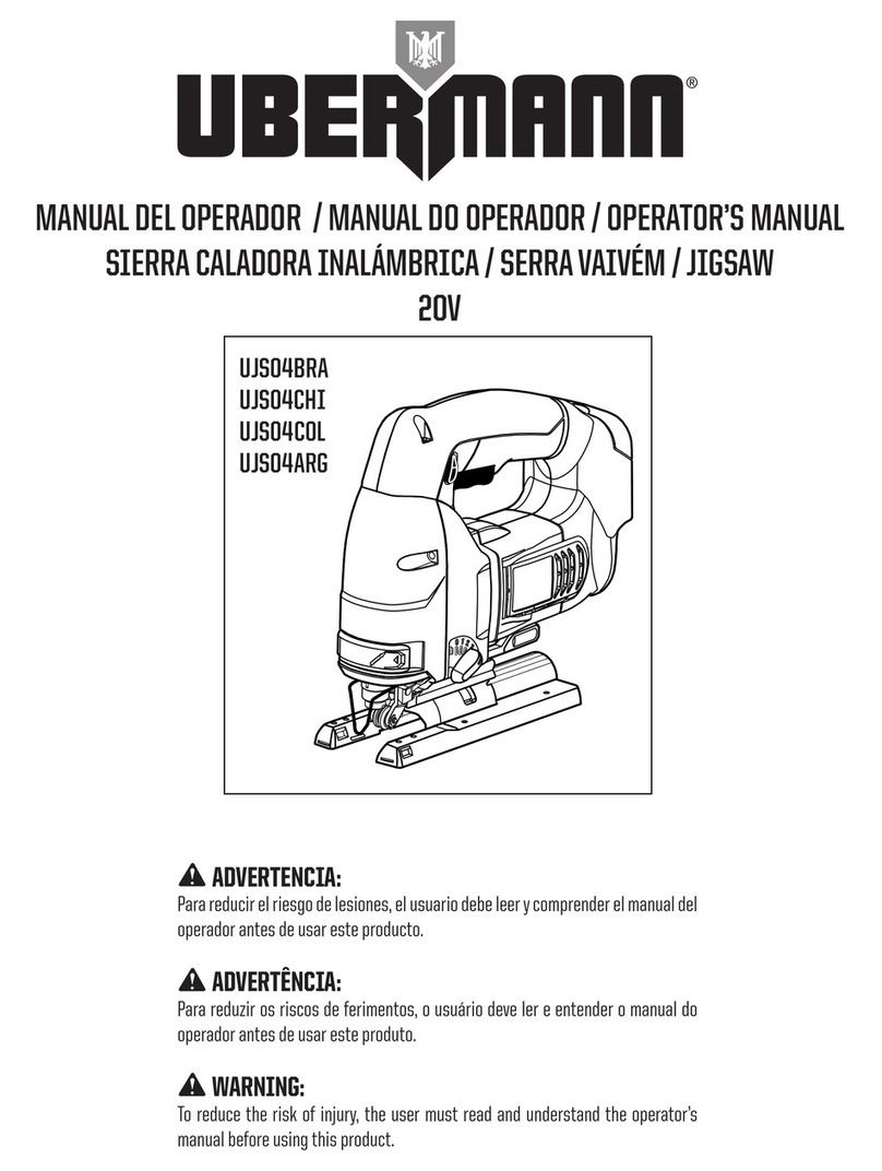
Ubermann UJS04BRA Operator's manual
Buffalo Tools
Buffalo Tools Black Bull DP16UL Assembly & operating instructions

Kärcher
Kärcher TLO 2-18 manual
wurth
wurth STP 120-A operating instructions
Festool
Festool OF 1400 EQ Operating instructions/spare parts list
