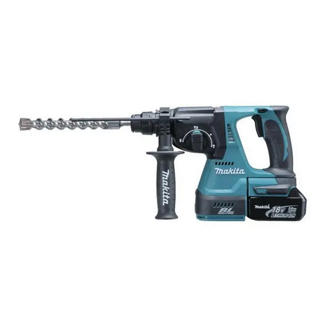
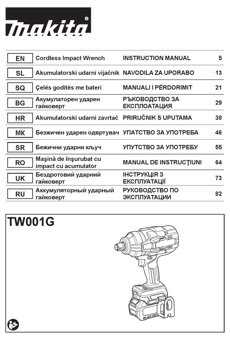
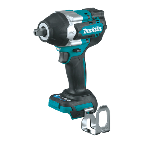
Makita DTW300 User manual

DTW300
DTW301
EN Cordless Impact Wrench INSTRUCTION MANUAL 4
SV Sladdlös mutterdragare BRUKSANVISNING 12
NO Batteridrevet slagskrutrekker BRUKSANVISNING 20
FI Akkukäyttöinen iskevä
mutterinväännin KÄYTTÖOHJE 28
DA Elektronisk akku slagnøgle BRUGSANVISNING 36
LV Bezvada LIETOŠANAS INSTRUKCIJA 44
LT NAUDOJIMO INSTRUKCIJA 52
ET Juhtmeta löökmutrivõti KASUTUSJUHEND 60
RU 68

Fig.1
Fig.2
Fig.3
Fig.4
Fig.5
Fig.6
Fig.7
2

Fig.8
Fig.9
Fig.10
Fig.11
Fig.12
Fig.13
Fig.14
3

4 ENGLISH
ENGLISH (Original instructions)
SPECIFICATIONS
Model: DTW300 DTW301
Fastening capacities Standard bolt M10 - M20
High tensile bolt M10 - M16
Square drive 12.7 mm
No load speed (RPM) Max impact mode 0 - 3,200 min-1
Hard impact mode 0 - 2,600 min-1
Medium impact mode 0 - 1,800 min-1
Soft impact mode 0 - 1,000 min-1
Impacts per minute Max impact mode 0 - 4,000 min-1
Hard impact mode 0 - 3,400 min-1
Medium impact mode 0 - 2,600 min-1
Soft impact mode 0 - 1,800 min-1
Overall length 144 mm
Rated voltage D.C. 18 V
Net weight 1.5 - 1.8 kg
•
-
est combination, according to EPTA-Procedure 01/2014, are shown in the table.
Applicable battery cartridge and charger
BL1815N / BL1820 / BL1820B / BL1830 / BL1830B / BL1840 /
BL1840B / BL1850 / BL1850B / BL1860B
Charger DC18RC / DC18RD / DC18RE / DC18SD / DC18SE / DC18SF /
DC18SH
•
WARNING: Only use the battery cartridges and chargers listed above.
Intended use
The tool is intended for fastening bolts and nuts.
Noise
-
ing to EN62841-2-2:
Model DTW300
Sound pressure level (LpA) : 97 dB(A)
Sound power level (LWA) : 108 dB (A)
Model DTW301
Sound pressure level (LpA) : 97 dB(A)
Sound power level (LWA) : 108 dB (A)
NOTE:
The declared noise emission value(s) has been
measured in accordance with a standard test method
NOTE:
WARNING: Wear ear protection.
WARNING: The noise emission during actual
value(s) depending on the ways in which the
tool is used especially what kind of workpiece is
processed.
WARNING: Be sure to identify safety mea-
sures to protect the operator that are based on an
estimation of exposure in the actual conditions of
use (taking account of all parts of the operating
cycle such as the times when the tool is switched
trigger time).

5 ENGLISH
Vibration
The vibration total value (tri-axial vector sum) deter-
mined according to EN62841-2-2:
Model DTW300
Work mode: impact tightening of fasteners of the maxi-
Vibration emission (ah) : 12.5 m/s2
2
Model DTW301
Work mode: impact tightening of fasteners of the maxi-
Vibration emission (ah) : 12.5 m/s2
2
NOTE: The declared vibration total value(s) has been
measured in accordance with a standard test method
NOTE:
WARNING: The vibration emission during
declared value(s) depending on the ways in which
the tool is used especially what kind of workpiece
is processed.
WARNING: Be sure to identify safety mea-
sures to protect the operator that are based on an
estimation of exposure in the actual conditions of
use (taking account of all parts of the operating
cycle such as the times when the tool is switched
trigger time).
EC Declaration of Conformity
For European countries only
to this instruction manual.
SAFETY WARNINGS
General power tool safety warnings
WARNING: Read all safety warnings, instruc-
with this power tool. Failure to follow all instructions
Save all warnings and instruc-
tions for future reference.
(cordless) power tool.
Cordless impact wrench safety
warnings
1. Hold the power tool by insulated gripping
surfaces, when performing an operation
where the fastener may contact hidden wiring.
exposed metal parts of the power tool "live" and
could give the operator an electric shock.
2. Wear ear protectors.
3. Check the impact socket carefully for wear,
cracks or damage before installation.
4.
5. Keep hands away from rotating parts.
6. Do not touch the impact socket, bolt, nut or the
workpiece immediately after operation.
7.
Be sure no one is below when using the tool in
high locations.
8.
depending upon the kind or size of the bolt.
Check the torque with a torque wrench.
SAVE THESE INSTRUCTIONS.
WARNING: DO NOT let comfort or familiarity
with product (gained from repeated use) replace
strict adherence to safety rules for the subject
product.
MISUSE or failure to follow the safety rules stated
in this instruction manual may cause serious
personal injury.
Important safety instructions for
battery cartridge
1. Before using battery cartridge, read all instruc-
tions and cautionary markings on (1) battery
charger, (2) battery, and (3) product using
battery.
2. Do not disassemble battery cartridge.
3. If operating time has become excessively
shorter, stop operating immediately. It may
result in a risk of overheating, possible burns
and even an explosion.
4. If electrolyte gets into your eyes, rinse them
out with clear water and seek medical atten-
tion right away. It may result in loss of your
eyesight.
5. Do not short the battery cartridge:
(1) Do not touch the terminals with any con-
ductive material.
(2) Avoid storing battery cartridge in a con-
tainer with other metal objects such as
nails, coins, etc.
(3) Do not expose battery cartridge to water
or rain.
A battery short can cause a large current
breakdown.

6 ENGLISH
6. Do not store the tool and battery cartridge in
locations where the temperature may reach or
exceed 50 °C (122 °F).
7. Do not incinerate the battery cartridge even if
it is severely damaged or is completely worn
8. Be careful not to drop or strike battery.
9. Do not use a damaged battery.
10. The contained lithium-ion batteries are subject
to the Dangerous Goods Legislation require-
ments.
forwarding agents, special requirement on pack-
aging and labeling must be observed.
For preparation of the item being shipped, consult-
ing an expert for hazardous material is required.
national regulations.
around in the packaging.
11. When disposing the battery cartridge, remove
it from the tool and dispose of it in a safe
place. Follow your local regulations relating to
disposal of battery.
12. Use the batteries only with the products
Installing the batteries to
-
13. If the tool is not used for a long period of time,
the battery must be removed from the tool.
SAVE THESE INSTRUCTIONS.
CAUTION: Only use genuine Makita batteries.
Use of non-genuine Makita batteries, or batteries that
charger.
Tips for maintaining maximum
battery life
1. Charge the battery cartridge before completely
discharged. Always stop tool operation and
charge the battery cartridge when you notice
less tool power.
2. Never recharge a fully charged battery car-
tridge. Overcharging shortens the battery
service life.
3. Charge the battery cartridge with room tem-
perature at 10 °C - 40 °C (50 °F - 104 °F). Let
a hot battery cartridge cool down before
charging it.
4. Charge the battery cartridge if you do not use
it for a long period (more than six months).
FUNCTIONAL
DESCRIPTION
CAUTION: Always be sure that the tool is
before adjusting or checking function on the tool.
Installing or removing battery
cartridge
CAUTION:
installing or removing of the battery cartridge.
CAUTION: Hold the tool and the battery car-
cartridge.
Fig.1: 1. Red indicator 2. Button 3.
while sliding the button on the front of the cartridge.
CAUTION: Always install the battery cartridge
fully until the red indicator cannot be seen. If not,
CAUTION: Do not install the battery cartridge
forcibly.
Tool / battery protection system
-
under one of the following conditions:
Overload protection
This protection works when the tool is operated in a
-
-
cation that caused the tool to become overloaded. Then
turn the tool on to restart.
Overheat protection
-
before turning the tool on again.
Overdischarge protection

7 ENGLISH
Indicating the remaining battery
capacity
Only for battery cartridges with the indicator
Fig.2: 1. Indicator lamps 2. Check button
-
light up for a few seconds.
Indicator lamps Remaining
capacity
Lighted Blinking
75% to 100%
50% to 75%
25% to 50%
0% to 25%
Charge the
malfunctioned.
NOTE: Depending on the conditions of use and the
Switch action
Fig.3: 1. Switch trigger
CAUTION: Before installing the battery car-
tridge into the tool, always check to see that the
switch trigger actuates properly and returns to
the "OFF" position when released.
trigger. Release the switch trigger to stop.
NOTE:
pulling the switch trigger for 6 minutes.
NOTE: When full speed mode is turned on, the rota-
For detail information, refer to the section of full speed
mode.
Lighting up the front lamp
CAUTION: Do not look in the light or see the
source of light directly.
Fig.4: 1. Lamp
Fig.5: 1. Button
To turn on the lamp status, press the button for
-
ton for one second again.
With the lamp status ON, pull the switch trigger to turn
trigger.
With the lamp status OFF, the lamp does not turn on
even if pulling the trigger.
NOTE:
the lamp status is ON. When the lamp does not come
on, the lamp status is OFF.
NOTE:
this case, cool down the tool before operating again.
NOTE:
the lamp. Be careful not to scratch the lens of lamp, or
NOTE: While pulling the switch trigger, the lamp
status cannot be changed.
NOTE:
the switch trigger, the lamp status can be changed.
Reversing switch action
Fig.6: 1. Reversing switch lever
CAUTION: Always check the direction of
rotation before operation.
CAUTION: Use the reversing switch only after
the tool comes to a complete stop. Changing the
-
age the tool.
CAUTION: When not operating the tool,
always set the reversing switch lever to the neu-
tral position.
This tool has a reversing switch to change the direction
of rotation. Depress the reversing switch lever from the
A side for clockwise rotation or from the B side for coun-
terclockwise rotation.
When the reversing switch lever is in the neutral posi-
tion, the switch trigger cannot be pulled.

8 ENGLISH
Changing the application mode
Changing the impact force
You can change the impact force in four steps: 4 (max), 3 (hard), 2 (medium), and 1 (soft).
This allows a tightening suitable to the work.
.
NOTE: -
ton or .
Fig.7
Application mode
(Impact force grade
displayed on panel)
Maximum blows Purpose Example of application
4 (Max) 4,000 min-1 (/min) Tightening with the maximum force
and speed.
Assembling steel frames and tighten-
ing long screws or bolts.
3 (Hard) 3,400 min-1 (/min) Tightening with less force and speed
than Max mode (easier to control than
Max mode).
Assembling steel frames.
2 (Medium) 2,600 min-1 (/min)
needed.
Assembling or disassembling scaf-
folds and frameworks.
1 (Soft) 1,800 min-1 (/min) Tightening with less force to avoid
screw thread breakage.
Assembling furniture.
: The lamp is on.
NOTE: When none of the lamp on the panel is lit, pull the switch trigger once before pressing the button .
NOTE:

9 ENGLISH
Changing the application mode
.
NOTE: -
ton or .
Fig.8
Application mode
(Assist type displayed on panel)
Feature Purpose
Bolt mode Clockwise
This mode helps to repeat screwdriving
also helps to reduce the risk of breakage
of bolts/nuts due to overtightening.
Counterclockwise
This mode helps to prevent a bolt from
tool driving in counterclockwise rotation,
after the bolt/nut gets enough loosened.
NOTE:
The timing to stop the driving varies
depending on the type of the bolt/nut
and material to be driven. Make a test
driving before using this mode.
Clockwise
Preventing over tightening of bolts.
Counterclockwise
Loosening bolts.
Bolt mode (1) Clockwise
it has started impact blows.
Counterclockwise
The impact force is 4. The tool stops
-
ened the bolt/nut.
–
Bolt mode (2) Clockwise
-
moment that the tool has started impact
blows.
Counterclockwise
The impact force is 4. The tool stops
-
ened the bolt/nut.
–
Bolt mode (3) Clockwise
-
that the tool has started impact blows.
Counterclockwise
The tool slows down the rotation after it
has loosened the bolt/nut.
–
: The lamp is on.
NOTE: When none of the lamp on the panel is lit, pull the switch trigger once before pressing the button .
NOTE:
Full speed mode
Fig.9: 1. Button 2. Lamp
When full speed mode is turned on, the tool speed becomes
To turn on full speed mode, press and hold the button . To
again.
The lamp turns on while full speed mode is on.
NOTE: Full speed mode continues even after switch-
ing the impact force mode/auto stop mode.
ASSEMBLY
CAUTION: Always be sure that the tool is
before carrying out any work on the tool.
Selecting correct impact socket
nuts. An incorrect size impact socket will result in inac-
curate and inconsistent fastening torque and/or damage
to the bolt or nut.

10 ENGLISH
Installing or removing impact socket
Optional accessory
CAUTION: Make sure that the impact socket
and the mounting portion are not damaged before
installing the impact socket.
CAUTION: After inserting the impact socket,
do not use it.
NOTE:
Tool with the ring spring
Model DTW300
For impact socket without O-ring and pin
Fig.10: 1. Impact socket 2. Square drive 3. Ring
spring
Push the impact socket onto the square drive until it
locks into place.
For impact socket with O-ring and pin
Fig.11: 1. Impact socket 2. O-ring 3. Pin
Move the O-ring out of the groove in the impact socket
and remove the pin from the impact socket. Fit the
impact socket onto the square drive so that the hole in
the impact socket is aligned with the hole in the square
drive.
Insert the pin through the hole in the impact socket and
square drive. Then return the O-ring to the original posi-
tion in the impact socket groove to retain the pin.
To remove the impact socket, follow the installation
procedures in reverse.
Tool with the detent pin
Model DTW301
Fig.12: 1. Impact socket 2. Hole 3. Square drive
4. Detent pin
Align the hole in the side of the impact socket with the
detent pin on the square drive and push the impact
socket onto the square drive until it locks into place. Tap
hard to remove, depress the detent pin while pulling the
impact socket.
Installing hook
CAUTION: When installing the hook, always
If not, the hook
Fig.13: 1. Groove 2. Hook 3. Screw
This can be installed on either side of the tool. To install
the hook, insert it into a groove in the tool housing on
either side and then secure it with a screw. To remove,
loosen the screw and then take it out.
OPERATION
CAUTION: Always insert the battery cartridge
all the way until it locks in place.
red indicator on the upper side of the button, it is not
Fig.14
the bolt or nut. Turn the tool on and fasten for the proper
fastening time.
the kind or size of the bolt, the material of the workpiece
to be fastened, etc. The relation between fastening
Proper fastening torque for standard bolt
1. Fastening time (second) 2. Fastening torque
Proper fastening torque for high tensile bolt
1. Fastening time (second) 2. Fastening torque

11 ENGLISH
NOTE: Hold the tool pointed straight at the bolt or nut.
NOTE:
NOTE:
cartridge.
check the torque with a torque wrench.
torque will be reduced.
2. Impact socket
• Failure to use the correct size impact socket
will cause a reduction in the fastening torque.
• A worn impact socket (wear on the hex end
or square end) will cause a reduction in the
fastening torque.
3. Bolt
class of bolt are the same, the proper fasten-
-
ter of bolt.
• Even though the diameters of bolts are the
of bolt and the bolt length.
bar somewhat reduces the fastening force of the
longer period of time.
5. The manner of holding the tool or the material
torque.
6. Operating the tool at low speed will cause a reduc-
tion in the fastening torque.
MAINTENANCE
CAUTION: Always be sure that the tool is
before attempting to perform inspection or
maintenance.
NOTICE: Never use gasoline, benzine, thinner,
alcohol or the like. Discoloration, deformation or
cracks may result.
To maintain product SAFETY and RELIABILITY,
OPTIONAL
ACCESSORIES
CAUTION: These accessories or attachments
are recommended for use with your Makita tool
accessories or attachments might present a risk of
for its stated purpose.
-
Center.
• Impact socket
• Extension bar
• Socket bit adapter
• Tool hanger
NOTE:

12 SVENSKA
SVENSKA (Originalinstruktioner)
SPECIFIKATIONER
Modell: DTW300 DTW301
Åtdragningskapaciteter Standardbult M10 - M20
Höghållfasta bultar M10 - M16
12,7 mm
Hastighet utan belastning
(RPM)
Max slagläge 0 - 3 200 min-1
Hårt slagläge 0 - 2 600 min-1
Medel slagläge 0 - 1 800 min-1
0 - 1 000 min-1
Slag per minut Max slagläge 0 - 4 000 min-1
Hårt slagläge 0 - 3 400 min-1
Medel slagläge 0 - 2 600 min-1
0 - 1 800 min-1
Total längd 144 mm
Märkspänning 18 V likström
Nettovikt 1,5 - 1,8 kg
•
-
nen enligt EPTA-procedur 01/2014 visas i tabellen.
Tillgänglig batterikassett och laddare
Batterikassett BL1815N / BL1820 / BL1820B / BL1830 / BL1830B / BL1840 /
BL1840B / BL1850 / BL1850B / BL1860B
Laddare DC18RC / DC18RD / DC18RE / DC18SD / DC18SE / DC18SF /
DC18SH
VARNING: Använd endast batterikassetter och laddare från listan ovan. Användning av andra batterikas-
setter och laddare kan orsaka personskada och/eller brand.
Avsedd användning
Buller
Den normala bullernivån för A-belastning är bestämd
enligt EN62841-2-2:
Model DTW300
pA) : 97 dB (A)
WA) : 108 dB (A)
Model DTW301
pA) : 97 dB (A)
WA) : 108 dB (A)
OBS: Det deklarerade bullervärdet har uppmätts i
enlighet med standardtestmetoden och kan användas
OBS:
Det deklarerade bulleremissionsvärdet kan också använ-
das i en preliminär bedömning av exponering för vibration.
VARNING: Använd hörselskydd.
VARNING: Bulleremissionen under faktisk
användning av maskinen kan skilja sig från det
deklarerade värdet, beroende på hur maskinen
används och särskilt vilken typ av arbetsstycke
som behandlas.
VARNING: -
hetsåtgärder för att skydda användaren, vilka är
grundade på en uppskattning av graden av expo-
nering för vibrationer under de faktiska använd-
ningsförhållandena, (ta, förutom avtryckartiden,
med alla delar av användarcykeln i beräkningen,
som till exempel tiden då maskinen är avstängd
och när den går på tomgång).
Other manuals for DTW300
5
This manual suits for next models
3
Table of contents
Other Makita Power Tools manuals

Makita
Makita JN1600 User manual

Makita
Makita 6704D User manual

Makita
Makita 3612 User manual

Makita
Makita BTW450 User manual

Makita
Makita DTW450XZ User manual

Makita
Makita DTW280 User manual

Makita
Makita M4301 User manual

Makita
Makita SG1250 User manual

Makita
Makita XWT04Z User manual

Makita
Makita JN3201 User manual

Makita
Makita DTW700 User manual

Makita
Makita 4326 User manual

Makita
Makita SG1250 User manual

Makita
Makita AN450H User manual

Makita
Makita AN621 User manual

Makita
Makita SG1251 User manual

Makita
Makita BJS160 User manual

Makita
Makita 9803 User manual

Makita
Makita DTS130 User manual

Makita
Makita MP001G User manual