OSAKA VACUUM TC163H User manual

H07401<2>
OPERATION MANUAL
SERIAL COMMUNICATION
POWER SUPPLY
FOR MOLECULAR PUMP
TC163H/TC203/TC223/TC353/TC523H/TC1104
TC443S/TC553/TC1003/TC1103/TC1503H/TC1813/TC3213
Before using the pump and the power supply, read carefully and understand
thoroughly the cautions in this manual.
Save this manual for future use and reference.
OSAKA VACUUM, LTD.
All manuals and user guides at all-guides.com
all-guides.com

H07401<2>
1
Definitions and symbols
In this manual, "Caution" and "Warning" are defined as follows:
Warning : To prevent an accident resulting in injury or death
If you don't follow it, it will cause an accident resulting in injury or death.
Caution : To prevent damage to the pump or power supply
If you don't follow it, it will cause damage to the pump (or power supply)
or injury.
Warning
Important description for preventing an accident resulting in injury or death when you
use the pump and power supply.
Caution
Important description for safe operation of pump and the power supply.
Caution
Before using the pump and power supply, be sure to read this manual for safe operation
of the pump and power supply. Operations not following the procedures in this manual
may cause a failure or accident resulting in injury etc.
All manuals and user guides at all-guides.com

H07401<2>
2
CONTENTS
Page
1.Preface------------------------------------------------------------------------- 3
2. Operation mode ------------------------------------------------------------- 3
3. Interface specifications ---------------------------------------------------- 5
3-1. Transmission specifications
3-2. Connector specifications
3-3. Cable specifications
4. Preparation ------------------------------------------------------------------ 6
4-1. Cable connection
4-2. Transmission configuration
5. Protocol specifications ----------------------------------------------------- 9
6.Commands-------------------------------------------------------------------- 9
6-1. Operation command
6-2. Monitor command
6-3. Error codes
6-4. Pump status
6-5. Alarm codes
7. Troubleshooting ------------------------------------------------------------11
All manuals and user guides at all-guides.com

H07401<2>
3
1. Preface
The power supply has a serial interface in conformity with RS232C. It operates the power
supply and monitors operational information through the upper host computer. In all operation
modes, all commands are effective except START and STOP.
1) Operations
Start/stop the pump
2) Monitor of operational information
Status (Standby / Acceleration / Normal / Brake / Reacceleration /Failure)
Details of failure
Total operational time of the power supply
Output frequency(Rotating speed)
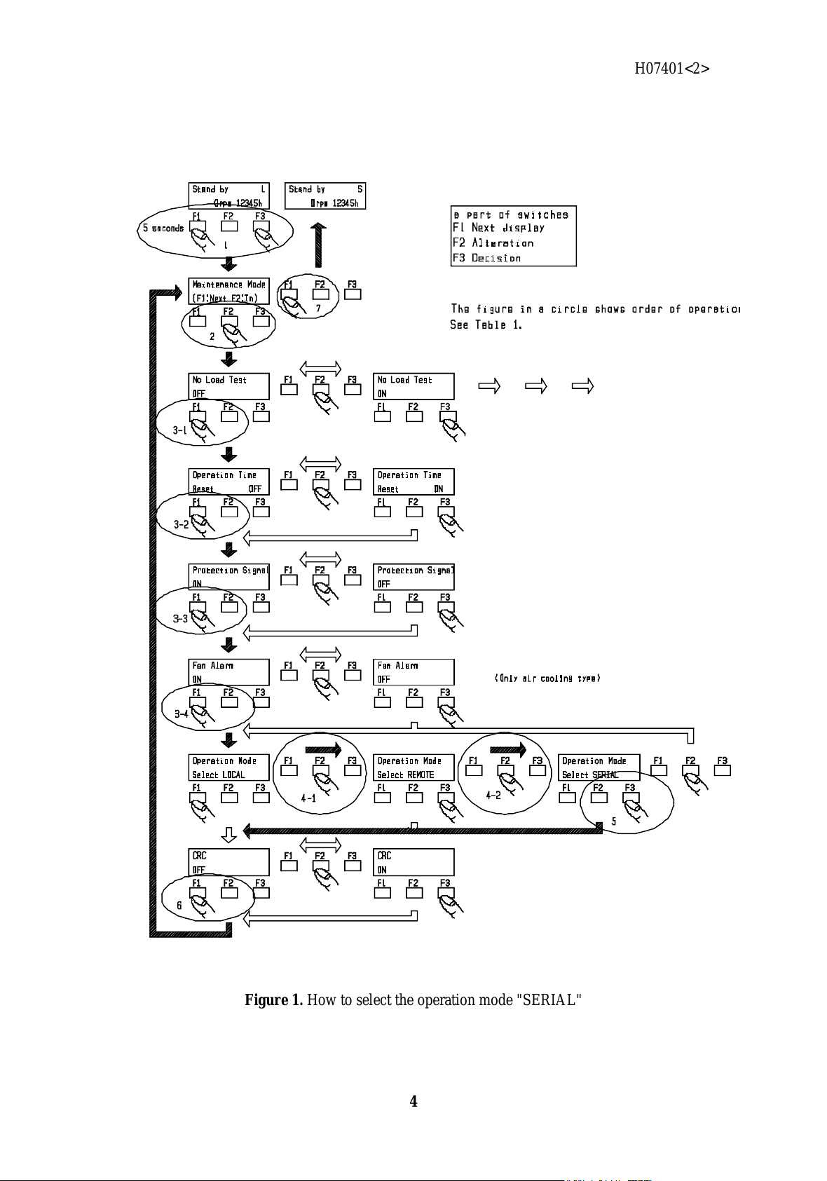
2. Operation mode
To operate on serial communication mode, it is necessary to select the operation mode
"SERIAL". How to select the operation mode "SERIAL" is shown in Table1 and Figure1.
Operation Explanation Display
1 Press the function buttons F1 and F3
(press the F3 button before F1
button.) simultaneously over 5
seconds when “Standby” is indicated
on display.
Select MAINTENANCE
MODE Maintenance Mode
(F1:Next F2:In)
2 Press the F2 button Enter into MAINTENANCE
MODE No Load Test
OFF
3 Press the F1 button four times Select Operation mode Opration Time
Reset OFF
/
Protection Signal
ON
/
Fan Alarm
OFF
/
Operation Mode
Select LOCAL
4 Press the F2 button twice Select SERIAL Operation Mode
Select REMOTE
/
Operation Mode
Select SERIAL
5 Press the F3 button Enter into SERIAL mode CRC
OFF
6 Press the F1 button Return to initial display Maintenance Mode
(F1:Next F2:In)
7 Press the F1 button Return to initial display Standby S
0 rpm 12345h
Table1. How to select the operation mode "SERIAL"
In all operation modes, all commands are effective except START(SDR1) and STOP(SDR0).
All manuals and user guides at all-guides.com
H07401<2>
4
Figure 1. How to select the operation mode "SERIAL"
All manuals and user guides at all-guides.com
H07401<2>
5
3. Interface specifications
3-1. Transmission specifications
Item Specification
Method of communication RS232C
Transmission speed 2400/4800/9600/19200(bps)
Parity bit none/odd/even
Start bit 1
Length of data bit 7/8
Length of stop bit 1/2
Protocol Refer to section 5, " Protocol specifications "
Control of flow Hard wear(RS/CS)
Note.1) "_"(under bar) is an initial value.
3-2. Connector specifications
Connector ("SERIAL" on the rear panel) D-Sub 9 pin male
(Daiichi dennshi 17JE-23090-02(D1))
Pin layout
Pin No. Signal
name(JIS) Status of signal Input/Output
1 - Not connected to inside -
2 RD Receive data Input
3 SD Send data Output
4 ER Data terminal ready Output
5 SG Signal ground -
6 - Not connected to inside -
7 RS Request to send Output
8 CS Permit to send Input
9 - Not connected to inside -
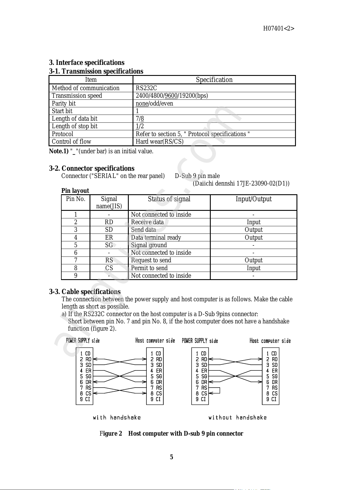
3-3. Cable specifications
The connection between the power supply and host computer is as follows. Make the cable
length as short as possible.
a) If the RS232C connector on the host computer is a D-Sub 9pins connector:
Short between pin No. 7 and pin No. 8, if the host computer does not have a handshake
function (figure 2).
Figure 2 Host computer with D-sub 9 pin connector
All manuals and user guides at all-guides.com
all-guides.com

H07401<2>
6
b) If the the RS232C connector on the host computer is a D-Sub 25 pin connector:
Short between pin No. 7 and pin. No. 8, if the host computer does not have a handshake
function (figure 3).
Figure 3 Host computer with D-sub 25 pin connector
4. Preparation
4-1. Cable connection
Cut off the input power of the power supply and the host computer. Then connect
"SERIAL" on the rear panel of the power supply to the host computer’s RS232C port with
a cable. Tighten the screws to secure the connector.
4-2. Transmission configuration
1) Push the “F1” button on front panel and change the page of the liquid crystal display.
The transmission configuration is displayed on page 3 as follows.
RS232C_Echo:OFF
9600_8 b i t_N_1sp
2) Next, push the "F2" button on front panel and change to the display for setting and
altering parameters. Parameter display changes every time the “F1” button is pushed,
like the following : " RS232C Speed " => " RS232C Length " => " RS232C Parity " =>
" RS232C Stop Bit ".
Select the parameter to alter by pushing the "F1" button (figure 4).
3) The value of the parameter changes every time the “F2” button is pushed. Select the
value to set (figure 5).
4) When the value to set is displayed, push the "F3" button to set the value.
5) Repeat the operation as described above in 2), 3), and 4) untill all parameters are set.
After all the parameters are set, push the “F1” button to return to page 1 of the display.
All manuals and user guides at all-guides.com

H07401<2>
7
Figure 4 Setting of transmission specifications
All manuals and user guides at all-guides.com

H07401<2>
8
Figure 5 Details of data setting
All manuals and user guides at all-guides.com

H07401<2>
9
5. Protocol specifications
1) String transmitted from host computer
Command (or command + parameter) + carriage return (0dh) is one unit. Use capital
letters for commands, and use capital letters or digits for parameters. No break mark is
needed between the command and the parameter.
To set two or more parameters, insert a space after each parameter.
2) String that host computer receives
Parameter (or “#” + error code) + carriage return (0dh) is one unit.
3) Sum check
The CRC method is used for checking sums (refer to the following for details). Transmit
“SCC1” from the host computer to check. Transmit “SCC0” with CRC code (*1) to end.
The power supply will send “#06” to host computer, if a CRC error has occurred.
(*1) The CRC code equivalent to "SCC0" is "b89a". In the event that CRC
communication is abnormally functioning, transmit "SCC0b89a" without the CRC
code.
<Details of the CRC method>
Make the CRC code in right-transmission with 0x8408 (in hexadecimal notation) witch is
generated from the Checking Polynomial(x16+x12+x5+1) 0x11021 (in hexadecimal notation) by
reversing right and left, according to CCITT(X.25) recommendations. To send a string, attach
the generated code (or command + parameter) as 4 byte data after the command. When
receiving, the 4byte data before the carriage return (0dh) is the CRC code.Samples of CRC code
are shown below.
Samples of CRC code
Without CRC code With CRC code
RRS RRS70ce
35 35f5a3
SCC0 SCC0b89a
6. Commands
6-1. Operation commands
Operation commands allow you to set the CRC configuration, to start/stop the pump, to
change the rated rotational speed and to confirm these operations.
Command Parameter Returned
value Function Example
(command) Example
(returned
value)
SCC [0,1] - Config CRC
[0]---Set CRC to null
[1]---Set CRC
effective
SCC1! -
SCC - [0,1] Read CRC setting SCC! 1!
SDR [0,1] - Start/stop pump
[0]---stop pump
[1]---start pump
SDR0! -
All manuals and user guides at all-guides.com

H07401<2>
10
Characters in table as above
Character Signification Character Signification
! CR [ ] Select one in [ ]
6-2. Monitor commands
Monitor commands are used to monitor the status of the pump .
Command Returned value
(normal) *1 Unit Function Example
(command) Example
(return value)
RDT d h Read the total
operational time of
pump
RDT! 100!
RSS [1,2,3,4,6,7] - Read the pump
status *2 RSS! 2!
RSA [1,#03,#12,#20
#23#30,#31,#32
#33,#34,#35,#60
#61]
- Read the failure
details
*3
RSA! #12!
RRS d Hz Read the output
frequency
(~rotating speed)
RRS! 100!
*1 Refer to section 6-3 "error code table" for returned value in case of failure.
“d” means decimal integer.
*2 Refer to 6-4 " pump status code table ".
*3 Refer to 6-5 " alarm code table ".
6-3.Error codes
When the command from the host computer is irregular, the power supply returns one of
the error codes described in the following table.
Table of error code
Code Signification
#00 There is no such command.
#01 The set parameter is irregular.
#02 The set parameter is beyond the available range.
#03 Despite failure, the operation command is inputted.
#05 The “operation mode select switch” is not set to SERIAL.
#06 The CRC code is irregular.
6-4. Pump status codes
The following table of pump status codes describes the signification of the returned value
to the command “RSS”. Table of pump status codes
Code Signification
1 Standby
2 Acceleration
3 Normal
4 Brake
6 Reacceleration
7 Failure
All manuals and user guides at all-guides.com
all-guides.com

H07401<2>
11
6-5. Alarm codes
The following table of the alarm codes describes the signification of return values to the
command "RSA". Table of alarm codes
Code Signification Code Signification
1 Normal #32 Motor temperature error
#03 Change Bearing warning #33 Excessive current
#12 Protection signal error #34 Excessive rotating speed
#20 External fan disconnected #35 Acceleration time over
#23 System error #55 P/S Fan stop error
#30 Input voltage low #60 Reacceleration time over
#31 Driver temperature error #61 No load
#03 is a code concerning only to TC223,TC353,TC1103,TC1104.
#55 is a code concerning only to TC443S,TC553,TC1003,TC1103,TC1503,TC1813,TC3213.
7. Troubleshooting
1) No string can be sent or received.
1.Check the cable connection
2.Check the transmission configuration
2) Received strings are irregular.
1.Check the transmission speed
2.Check the data bit length
3.Check the parity bit
3) Characters sometimes change and a CRC code error occurs
1.Remove noise source
2.Change the cable to shielded cable
3.Replace the cable with a shorter one
4.Reduce the transmission speed
All manuals and user guides at all-guides.com

H07401<2>
12
OSAKA VACUUM, LTD.
CA OFFICE : 911 Bern Court, Suite 140, San Jose, CA 95112
(PHONE) 408-441-7658 (FAX) 408-441-7660
HEAD OFFICE : Nissay-Yodoyabashi Bldg., 5-29, Kitahama 3-chome, Chuo-ku, Osaka
541-0041, Japan
(PHONE) +81-6-6203-3981 (FAX) +81-6-6222-3645
TOKYO OFFICE : Ginza Showa-Dori Bldg., 8-14-14, Ginza, Chuo-ku, Tokyo 104-0061,
Japan
(PHONE) +81-3-3546-3731 (FAX) +81-3-3546-1560
HACHIOUJI FACTORY : Kunugida-cho, Hachiouji-shi, Tokyo 193-0942, Japan
(PHONE) +81-426-64-5301 (FAX) +81-426-63-2016
All manuals and user guides at all-guides.com

STANDARDWARRANTYCONDITIONS
OSAKAVACUUM,LTD.
Article1Warranty
IndeliveryoftheproductindicatedintheDeliverySpecificationsand/ortheInst‑
ructionManual(Product),wewarrantthattheProductisdesignedandmanufactured
inaccordancewithourregulation,standardorruleetc.withrespecttodesign,pur‑
chase,manufactureandqualitycontrolunderISO9001StandardorISO9002Standardas
wellasthespecificationsinthesalescontract,andthatthereisnodefectindesi‑
gn,materialsormanufactureoftheProduct.
Article2Indemnification
InrelationtotheProduct,incaseanydefectindesign,materialsormanufacture
obviouslyattributabletousisfoundwithinthewarrantyperiod,oneyearfromthe
deliverydateoftheProduct(unlessotherwisestipulatedinwrittendocuments),
andanoticeofsuchdefectisimmediatelygiventous,wewill,atourelection,
correct,repairorreplacesuchdefectivepart,orreplacethewholeProductwithout
charge.ThereplacementisavailableonlyforstandardProducts,andnoreplacement
maybeallowedforanyCustom‑madeProduct.
Article3Exception
ThewarrantyandrelevantindemnificationshallbeappliedonlywhentheProductis
properlyinstalledorfixed,handled,used,storedandappropriatelymaintainedby
auserinaccordancewiththeinstructionsstipulatedintheDeliverySpecifications,
theInstructionManualoftheProduct,otherhandlinginstructionsofoursand/orthe
RelatedTechnicalDocumentswhichweprovide(RelatedTechnicalDocuments).
Unlessotherwisestipulatedinotherwrittendocument,thewarrantyandrelevant
indemnificationshallnotbeappliedtothecasesdescribedbelow;
(1)AnyfailureduetoanyusageoftheProductnotdescribedintheRelatedTechnical
DocumentsoftheProduct,oranyotherirregularusageoftheProduct;
(2)DeteriorationoftheProductduetocorrosivegases,organicsolvent,radioactive
rays,electromagneticfieldetc.;
(3)Expendablepartsandwearablepartssuchaslubricantetc.;
(4)Anyfailureduetorepairorreconstructionbyanypartyotherthanus;
All manuals and user guides at all-guides.com

(5)RepairedProducts(theStandardWarrantyConditionsforRepairedProductswill
applytotherepairedProducts);
(6)Aninsignificantdeviationfromthespecificationsinthesalescontractwhich
hasnoeffectonperformanceorfunctionoftheProduct;
(7)Anyfailureduetofire,flood,earthquake,lightningstrikeoranyotherevent
causedbyforcemajeure.
Article4ScopeofIndemnification
Thescopeofourindemnificationshallbelimitedtothecorrection,repairor
exchangeofdefectivepartsoftheProductdelivered,orreplacementofthewhole
Product(incaseofthestandardProductonly),
andshallnotincludeanycompensationfortheconsequentialdamagesandbusiness
lossesincludingthefollowing;
(1)CostsandexpensesaccruedinconnectionwiththeremovalofthefailedProduct
fromtheequipmentinwhichtheProducthasbeeninstalled;or
(2)Costsandexpensesaccruedinconnectionwithinstallmentoftherepaired
Productorreplacementtotheequipment.
Inaddition,thetotalamountoftheindemnificationshallbelimitedtothe
contractpriceoftheProduct.
AsforUsageoftheProductnotdescribedintheRelatedTechnicalDocumentsofthe
ProductstipulatedinArticle3ofthisStandardWarrantyConditions,suchusage
shallbeincludedinthescopeofindemnificationunderthisStandardWarrantyCondi‑
tionsonlywhenweagreeinwritingpriortotheuseoftheProduct.
All manuals and user guides at all-guides.com

All manuals and user guides at all-guides.com
all-guides.com
Other manuals for TC163H
1
This manual suits for next models
13
Table of contents
Other OSAKA VACUUM Power Supply manuals


Popular Power Supply manuals by other brands

Videx
Videx 520MR Installation instruction

Poppstar
Poppstar 1008821 Instructions for use

TDK-Lambda
TDK-Lambda LZS-A1000-3 Installation, operation and maintenance manual

TDK-Lambda
TDK-Lambda 500A instruction manual

Calira
Calira EVS 17/07-DS/IU operating instructions

Monacor
Monacor PS-12CCD instruction manual


