Osaka CI 49 User manual

OSAKA-CI 49 Operating instructions. PAGE 1
CI49
MICROPROCESSOR-BASED
DIGITAL ELECTRONIC
PULSE COUNTER
OPERATING INSTRUCTIONS
PREVIOUS STATEMENT
In this manual are contained all the necessary information for a
correct installation and the instructions for the use and the
maintenance of the product; we recommend, therefore, to read
carefully the following instructions.
The maximum care has been used in the realisation of this
document, anyway OSAKA does not assume any responsibility
deriving from the use of itself.
The same consideration has to be done for each person or
Company involved in the creation of this manual.
The herewith issue is an exclusive property of OSAKA which
forbids any reproduction and divulgation, although partial, if not
expressly authorised.
OSAKA reserves the right to execute aesthetically and
functional modifications, at any moment and without any notice.
INDEX
1INSTRUMENT DESCRIPTION
1.1 GENERAL DESCRIPTION
1.2 FRONT PANEL DESCRIPTION
2PROGRAMMING
2.1 SET POINT PROGRAMMING
2.2 PARAMETERS PROGRAMMING
2.3 PARAMETERS LOCK
3INSTALLATION AND USE ADVICES
3.1 USE ALLOWED
3.2 MECHANICAL MOUNTING
3.3 ELECTRICAL CONNECTIONS
3.4 ELECTRICAL CONNECTION DRAWING
4OPERATING MODE
4.1 COMMANDS OPERATING MODE
4.2 DISPLAY OPERATING MODE
4.3 OUT 1 OPERATING MODE
4.4 OUT 2 OPERATING MODE
5PROGRAMMABLE PARAMETERS
5.1 PARAMETERS TABLE
5.2 PARAMETERS DESCRIPTION
6TROUBLES, MAINTENANCE, WARRANTY
6.1 CLEANING
6.2 WARRANTY AND REPAIRS
7TECHNICAL DATA
7.1 ELECTRICAL DATA
7.2 MECHANICAL DATA
7.3 MECHANICAL DIMENSIONS, PANEL CUT OUT AND
FIXING DEVICE
7.4 FUNCTIONAL DATA
7.5 INSTRUMENT CODE
1 -INSTRUMENT DESCRIPTION
1.1 –GENERAL DESCRIPTION
CI 49 is a programmable microprocessor based counter with
1or 2outputs. The instrument offers the possibility to program:
up to 2 set points, 3 operating modes for the output OUT1, 4
operating modes for the output OUT2, 2 counting mode (UP or
DOWN) and offers the possibility of counting division. The
counting state is visualised on 4 digits display while the outputs
state is signalised by 2 led. The instrument can have 2 outputs
(relay or to drive solid state relays) and 2 digital inputs, one for
counting (CNT) and one programmable as RESET or reverse
counting. The digital inputs signals can be for free voltage
contacts or voltage signals (the same voltage supply value).
The programming of the instrument is possible by means of the
3 keys placed on the front where is also a reset key (F)..
1.2 -FRONT PANEL DESCRIPTION
1 -Key Set : Used for the set point setting and to program the
functioning parameters
2 -Key DOWN : Used to decrease the values or to select
parameters
3 -Key UP : Used to increase the values or to select
parameters
4 -Key F : Used to reset the count
5 -Led OUT 1 : It indicates when the output OUT1 is on or off.
6 -Led OUT 2 : It indicates when the output OUT2 is on or off.
7 -Led SET/CNT : Signalize the set point or the parameters
programming mode (flashing fast), the count on (on) or reset
mode (off).
2 -PROGRAMMING
2.1 -SET POINTS PROGRAMMING
The instrument permits to program up to 2 sets: “C1” and
“C2”.
To program this sets do proceed as follows :
Pushing Key Set and keeping it pushed for 1 sec. approx., the
display will visualize “C1” and led SET/CNT will blink rapidly.
Releasing the key, on the display will be visualized the
programmed Set Point “C1”.
To modify it, work on keys UP, to increase the value or on key
DOWN, to decrease it.
If the OUT2 programmed functioning mode require the set “C2”
(F2 = 3 or 4), for programming this pressing Key Set again and
the display will show “C2”.
Releasing the key, on the display will be visualized the
programmed Set Point “C2” and will be possible to modify it by
the key UP or DOWN.

OSAKA-CI 49 Operating instructions. PAGE 2
The outgoing from the set points programming it’s automatically
obtainable not working on any key for 5 sec. approx. or
pressing only one time the key F, thus the counting value willl
again be displayed.
The programming of the sets is always possible, both with
counting on or off.
2.2 -PARAMETERS PROGRAMMING
To have access at the functioning parameters, it’s necessary to
push Key Set and keep it pushed for 5 sec. approx.
After 4 sec. will appear the label of the first parameter ("F1").
Now it possible to release Key Set and it will appear the value
programmed for parameter "F1".
To modify this value work on keys UP or DOWN.
Once the desired value has been programmed, pushing again
Key Set the display will show the label of the successive
parameter.
Releasing then key Set, it will appear the value programmed for
that parameter which can be modified working on keys UP and
DOWN.
Pushing and releasing Key Set it’s possible to visualize all the
parameters labels (when key is pushed) and the relative
programming (when key is released) one after the other.
The outgoing from the parameters programming it’s obtainable
not working on any key for 20 sec. approx. or pressing only one
time the key F, thus the counting value willl again be displayed.
P.A.: During the counting is not possible to enter in the
parameters programming mode.
2.3 -PARAMETERS LOCK
It’s possible to lock the access at the programming parameters
with the following procedure :
Switch off the instrument, push Key Set and keep it pushed
while the instrument is switched on again.
After approx. 5 sec. on the display will appear "uL" (unlock)
which indicates that the parameters are accessible.
Keeping pushed Key Set and pushing key DOWN it will appear
"Lo"
(lock) which indicates that the parameters are not accessible.
Release Key Set to exit from this modality.
The display will go back to the normal functioning, the
parameters will not be accessible anymore and it will only be
possible to modify the Set Point.
To have again access at the parameters, repeat the same
procedure pushing Key Set and selecting "uL" ; finally go out
from the parameters lock modality.
3 -INSTALLATION AND USE ADVICES
3.1 -PERMITTED USE
The instrument has been projected as measure and
control device, built according to EN61010-1 for the
altitudes operation until 2000 ms.
The use of the instrument for applications not expressly
allowed by the above mentioned rule has to foreseen proper
protection devices.
The instrument CAN’T be used in environments with dangerous
atmosphere (flammable or explosive) without a proper
protection.
It has to be reminded that the user has to take care that the
electromagnetic rules are being respected also after the
instrument installing, eventually using proper filters.
Whenever a failure or a bad functioning of the instrument may
cause dangerous situations or damage to people, things or
animals it has to be reminded that the plant has to be equipped
with additional electromechanical devices in order to grant the
safety.
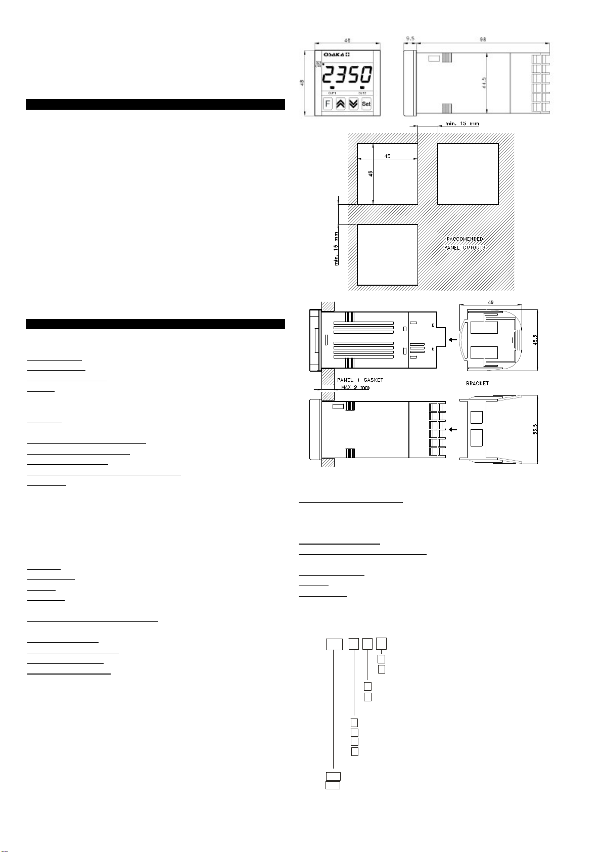
3.2 -MECHANICAL MOUNTING
The instrument, in DIN case 48 x 48 mm, is designed for flush-
in panel mounting. Make a hole 45 x 45 mm and insert the
instrument, fixing it with the provided special bracket. We
recommend to mount the gasket to obtain the front protection
degree as declared. Do avoid to place the instrument in
ambient with very high humidity ordirt that may create
condensation or introduction into the instrument of conductive
substances. Ensure the adequate ventilation to the instrument
and avoid the installation within boxes where are placed
devices which may overheat or have as a consequence the
instrument’s functioning at higher temperature than allowed
and declared. Connect the instrument as far as possible from
source of electromagnetic disturbances so as motors, power
relays, relays, electrovalves,etc. The instrument is removable
from its housing by the front side : is recommended to
disconnect the power supply from the instrument when it’s
necessary to effectuate this operation.
3.3 -ELECTRICAL CONNECTIONS
Carry out the electrical wiring connecting only one wire for each
terminal , according to the following diagram, checking that the
power supply is the same as indicated on the instrument and
the loads current is not higher than the maximum current
admitted. The instrument, being a built in equipment with
permanent connection into a cabinet, is not equipped neither
with switches nor with internal devices protecting from
overcurrent : the installation shall employ atwo-phase circuit-
breaker, placed as near as possible to the instrument, located
in a position easily reachable by the user and marked as
instrument disconnecting device. It's recommended,
furthermore, to properly protect all the electric circuits
connected to the instrument, with devices (ex. fuses)
proportionate to the circulating currents. It's strongly
recommended to use cables with proper insulation, according
to the working voltages and temperatures. Furthermore, the
input cable of the probe has to be kept separate from line
voltage wiring. If the input cable of the probe is screened, it has
to be connected on the ground with only one side. Finally, it is
advisable to check that the parameters are those desired
before connecting the outputs to the actuators in order to avoid
plant anomalies which may cause injuries to people, things or
animals.
OSAKA and its legal representatives are not responsible
for any eventual damages to people, things or animals
deriving from the instrument violation, not proper or wrong
use or in any case not in accordance with the instrument
features.
3.4 -ELECTRICAL CONNECTION DRAWING

OSAKA-CI 49 Operating instructions. PAGE 3
4-OPERATING MODE
4.1 –FUNCTIONING OF THE COUNTING COMMANDS
To the first pulse received by the CNT input the counter goes in
counting mode that is signalled by the led SET/CNT.
Under this condition it is possible to visualize and to modify the
set, but it is not possible to program the parameters.
To enter in the parameters programming mode is needed to
reset the counter through the RESET input if par. “E”=1 or the
key F if par. "t" = 1.
The reset of the display and of the output happens
automatically when operation mode is "F1" = 1 (Restart) or "F1"
= 2 (Restart-lap) or can be manual through the RESET input if
par. “E”=1 or the key F if par. "t" = 1.
Through the parameter "E" it is possible to use the RESET
input to operate as command of reverse counting.
When you program the par. "E" = 2 to the activation of the input
the counting is reversed and therefore the acquired pulses are
subtracted if countig mode is UP ("C"=1) or added if countig
mode is DOWN ("C"=2).
In this operation mode it is necessary to pay attention at
counting speed because the Reset input have a delay of 15
msec. and therefore the inversion of the calculation is not
instant.
For this reason the use of the function recommends only when
the input frequency is low.
Using a contact that closes with advance in comparison to the
other to which is connected is possible to realize, for instance,
the following application of UP/DOWN counting.
With this UP/DOWN counting applications the counting cannot
assume negative values and therefore reached the value 0
(counting UP) or the set value (counting DOWN) others pulses
can’t be acquired.
In order of the model the counting signal can be from free
voltage contacts, from devices with transistor output NPN
(models with inputs C) or from voltage signals with the same
voltage of the instrument supply (models with inputs V).
The instruments with inputs type C have besides an output (12
VDC) to supply the counting device (proximity, photocell or
other) with transistor output NPN.
In order to the counting frequency is advisable to program the
filter software of the par. "H" that it allows to select the
maximum counting frequency and to avoid false counting (for
instance caused by the contacts rebounds).
Particularly for the instruments with inputs type V (voltage
signals) it recommends to program the parameter "H"< 3
because the instrument could count the pulses produced by the
main supply frequency.
4.2 –FUNCTIONING OF THE DISPLAY
The led SET/CNT is used to indicate the access into the
programming (flashing), the counting in action (on) or the
counting finished and the state of reset (off).
The counting in action is considered when the first pulse is
acquired after the reset.
After the reset, the display visualizes 0000 if the counting mode
is programmed as UP (par. "C" = 1) or it visualizes the
programmed set value if the counting mode is programmed as
DOWN (par. "C" =2).
The par. “d” permits the user to divide the number of pulses
received by the input and to use the result as the counting
value of the counter (both for display and the outputs operating
mode).
4.3 -OUT1 OPERATING MODE
The instrument can be programmed by the parameter "F1" to
operate in any of the following 3 modes:
F1 = 1 -RESTART:
When reaching the programmed set or the 0000 value
(depending on whether the counting mode is UP or DOWN) the
ouput OUT1 is activated and it remains in this state for the
whole time programmed in the "r" parameter; the display
shows the value reached, and the counter does not count any
pulses received during this time.
When the "r" time has elapsed the output is deactivated and
the counter automatically resets counting, thus setting itself for
a new cycle: it then starts again to count the pulses received.
Therefore, reset of counting and output occurs when the "r"
time has elapsed.
F1 = 2 -RESTART-LAP:
This operating mode is similar to the previous one, the only
difference being that during the "r" time the counter -even
though it continues to display the value reached and maintains
the output activated -counts all the eventual pulses it receives.
When the "r" time has elapsed, output is deactivated and
counting continues starting from the value reached during the
"r" time.
Therefore, the counting reset occurs when the programmed set
has been reached, while the output OUT1 reset is carried out
when the "r" time has elapsed.
F1 = 3 -COUNT:
The output OUT1 is activated when the programmed set or the
0000 value have been reached (counting mode may be UP or
DOWN), and it remains activated until receiving the manual
reset control, which can be transmitted by the remote input
RES or the front key.

OSAKA-CI 49 Operating instructions. PAGE 4
4.4 -OUT2 OPERATING MODE
The instrument can be programmed by the parameter "F2" to
operate on OUT2 in any of the following 4 modes:
F2 = 1 -Output OUT2 operating like OUT1
The output OUT2 exactly operates like the output OUT1 so that
to be able to have two output contacts.
F2 = 2 -Output OUT2 operating as counting in progress
The output OUT2 is activated when the first pulse is acquired
and remains activated to the reset command.
F2 = 3 -Same function of OUT1 with set C2 absolute:
The choice of this mode of operation enable the set "C2" that
cannot be higher of "C1."
The instrument operating on the output OUT 2 in the same way
with which it operates the function F1 on the output OUT1 but
with set “C2”.
F2 = 4 -Same function of OUT1 with set C2 relative to set C1
(in advance) :
The choice of this mode of operation enable the set "C2" that
cannot be higher of "C1".
The instrument operating on the output OUT 2 in the same way
with which it operates the function F1 on the output OUT1 but
with set [”C1” -"C2"].
In the programming mode of the set "C2" the display shows
"C2 d" to indicate that the set C2 is dependent.
If “F2” = 0 the output OUT 2 is always disabled.
5 -PROGRAMMABLE PARAMETERS
5.1 -PARAMETERS TABLE
Par. Description Range Def.
1F1 OUT 1 operating mode 1 -2 -3 1
2F2 OUT 2 0perating mode 0 -1 -2 -3 -4 0
3H1 Maximum set 0000 .. 9999 9999
4CCounting mode 1 -2 1
5rRestart time 1 ... 250
décimas de seg.
1
6HMaximum frequency of
input 1 -2 -3 -4 -5 2
7dCounting division 1 ... 9999 1
8bBack-up mode 1 -2 1
9ERES input operating
mode 1 -2 1
10
tkey operating mode 0 -1 1
5.2 -PARAMETERS DESCRIPTION
F1-OUT 1 OPERATING MODE: Permits the user to select
the operating mode of the output OUT 1 as regards counting.
The 3 mode are:
1 = RESTART
2 = RESTART-LAP
3 = COUNT
F2-OUT 2 OPERATING MODE: Permits the user to select
the operating mode of the output OUT 2 as regards counting.
The 5 mode are:
0 = Ouput disable
1 = Operating like OUT1
2 = On during counting
3 = Same function of OUT1 with set C2 absolute
4 = Same function of OUT1 with set C2 dependent from set C1
H1 -HIGH SET POINT C1 : This parameter allows the user to
program the Higher value programmable as Set Point “C1”
C -COUNTING MODE: It establishes whether counting must
be carried out by increments (UP) or decrements (DOWN), i.e.
whether the display must show the pulses which have been
counted or remaining pulses. The options are:
1 = UP
2 = DOWN
r -RESTART AND RESTART-LAP TIME: This parameter
allows the user to determine the automatic reset delay time in
"F1"= 1 and "F1"= 2 operating modes (refer to what has
already been said in the description of these operating modes).
Programming options for this parameter are: 1 ... 250 (tenths of
sec.)
H -MAXIMUM COUNTING FREQUENCY: This parameter acts
on asoftware filter and allows the user to select the maximum
acceptable input frequency for counting, and it is used
according to the type of signal transmitted at the input port
(from relay, contact, encoder, etc.). The options are:
1 = 2 Hz
2 = 10 Hz
3 = 40 Hz
4 = 125 Hz
5 = 1000 Hz
d -COUNTING DIVISION: This parameter permits the user to
divide the number of pulses received by the counting input and
to use the result as the counting value of the counter (both for
display and the output operating mode). Programming options
for this parameter are: 1 ... 9999
b -BACK-UP MODE : It determines counter behaviour in case
of power failure. The options are:
1 = It stores counting: in the eventuality of power failure the
counter stores the value reached, and when the power supply
is restored it restarts counting from this value.
2 = It resets counting: in the eventuality of power failure the
counter does not store the value reached, and when the power
supply is restored it restarts counting from 0000 (if in UP mode)
or the set value (if in DOWN mode).
E -RES INPUT OPERATING MODE. Allows the user to select
the operating mode of the RES external input. The options are:
1 = RESET
2 = REVERSE COUNTING

OSAKA-CI 49 Operating instructions. PAGE 5
t -U KEY OPERATING MODE: This parameter permits to
decide the operating mode of the frontal U key and the
possibilities are:
0 = Key disable
1 = RESET
6-PROBLEMS, MAINTENANCE AND WARRANTY
6.1 –CLEANING
It’s recommended to clean the instrument only with a cloth
welted with water or with a detergent neither abrasive nor
containing solvents.
6.2 –WARRANTY AND REPAIRS
The instrument is under warranty against construction vices or
defected material, noticed within 12 months from delivery date.
The warranty is limited to the repairs or to the substitution of
the instrument. The eventual opening of the housing, the
violation of the instrument or the wrong use and installation of
the product means the automatic decay of the warranty.
In case of defected instrument, noticed in warranty period or
out of warranty, do contact our sales department to obtain the
shipment authorisation.
The defected product must be shipped to OSAKA with the
detailed description of the failures found and without any fees
or charge for OSAKA, safe different agreements.
7 -TECHNICAL DATA
7.1 –ELECTRICAL DATA
Power supply: 12 VDC/VAC, 24, 115, 230 VAC +/-10%
Frequency AC: 50/60 Hz
Power consumption: 3 VA approx.
Input/s: 2 digital inputs for Count (CNT) and Reset (RES) for
voltage-free contacts or voltage signals (the same voltage
supply value).
Output/s: Up to 2 outputs. Relay SPDT (8 A-AC1, 3 A-AC3 /
250 VAC); or in tension to drive SSR (12VDC/15 mA).
Electrical life for relay outputs: 100000 operat.
Voltage inputs absorption: 1 mA Max.
Installation category: II
Protection class against electric shock: Class II for Front panel
Insulation: Reinforced insulation between the low voltage
section (supply and relay outputs) and the front panel;
Reinforced insulation between the low voltage section (supply
and relay outputs) and the extra low voltage section (inputs,
SSR outputs); Reinforced insulation between the extra low
voltage section (SSR outputs) and voltage inputs.
7.2 –MECHANICAL DATA
Housing: Self-extinguishing plastic, UL 94 V0
Dimensions: 48 x 48 mm DIN, depth 98 mm
Weight: 200 g approx.
Mounting: Flush in panel in 45 x 45 mm hole
Connections: 2 x 1 mm 2 screw terminals block
Degree of front panel protection : IP 54 mounted in panel with
gasket
Pollution situation: 2
Operating temperature: 0 ... 50 °C
Operating humidity: 30 ... 95 RH% without condensation
Storage temperature: -10 ... +60 °C
7.3 –MECHANICAL DIMENSIONS, PANEL CUT OUT AND
FIXING DEVICE [mm]
7.4 –FUNCTIONAL DATA
Outputs operating mode: 3 modes for OUT 1: RESTART,
RESTART-LAP, COUNT. 4 modes for OUT 2: like OUT1, ON
during count, like OUT1 with set C2 absolute or relative in
advance.
Measurement range: 9999 Max.
Max counting input frequency: programmable from 2Hz up
1000 Hz
RES Input delay: 15 m sec. Max.
Display: 4 Digit Red h 12 mm
Compliance: ECC directive EMC 89/336 (EN 61326), ECC
directive LV 73/23 and 93/68 (EN 61010-1)
7.5 –INSTRUMENT CODE
CI
= formato (48x48), Ip65
= formato (72x72), Ip65
=230 Vac
= 24 Vac
= 2 relés
=110 Vac
= 12 Vac/dc
= a la conexión
= standard
= salida SSR+Relé
-
C
SR
49
73
A
B
E
D
Table of contents