Osburn 1600 User manual

READ AND KEEP THIS MANUAL FOR REFERENCE
45022
OWNER`S MANUAL
1600 MODEL STOVE
US ENVIRONMENTAL PROTECTION
AGENCY PHASE II CERTIFIED
WOODSTOVES
OREGON DEPARTEMENT
ENVIRONMENTAL QUALITY
Verified and tested following
ULC S627 and UL 1482 Standards
Australian standard 2918 : 1990 appendix B
New Zeland standard 7421 : 1985
by:
Intertek Testing Services
Manufactured by : STOVE BUILDER INTERNATIONAL INC..
1700, Léon-Harmel, Québec (Québec) G1N 4R9
Tel : (418 ) 527-3060
Fax : (418 ) 527-4311
www.osburn-mfg.com

1
TABLE OF CONTENTS
INTRODUCTION................................................................................................................. 2
TECHNICAL SPECIFICATIONS ......................................................................................... 3
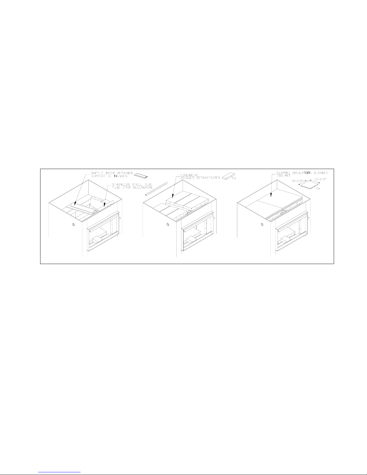
ASSEMBLY ......................................................................................................................... 4
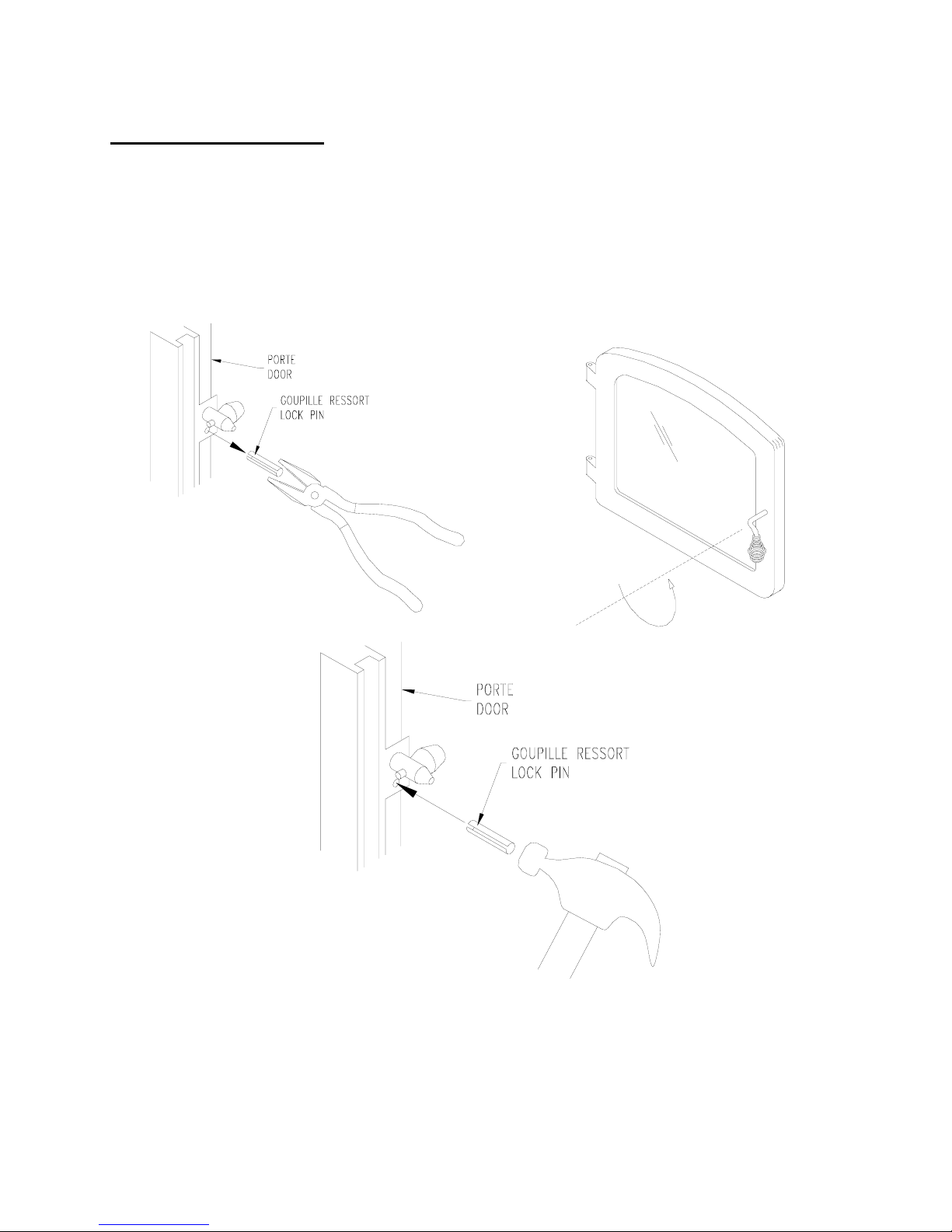
DOOR ADJUSTMENT ..................................................................................................... 6
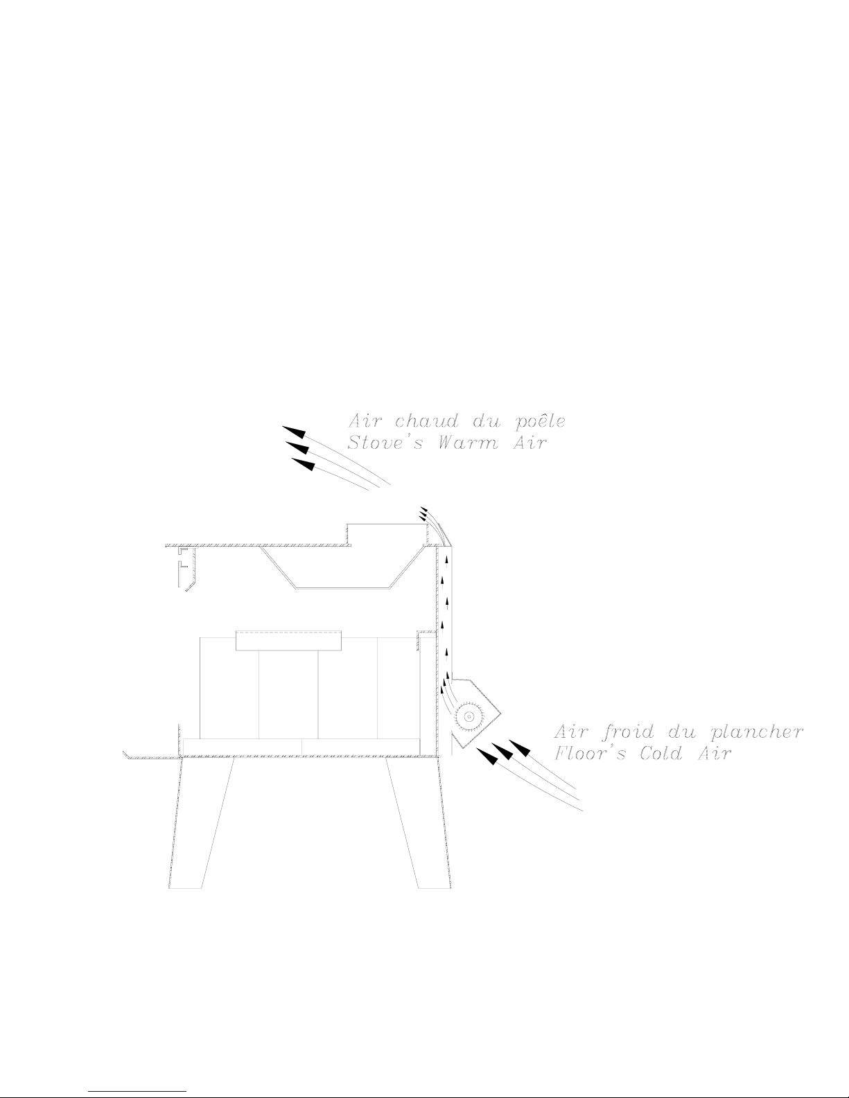
THE BENEFITS OF INSTALLING A BLOWER ................................................................... 7
INSTALLATION................................................................................................................... 8
POSITIONING THE STOVE ............................................................................................ 8
FLOOR PROTECTOR..................................................................................................... 9
CLEARANCES FROM COMBUSTIBLES ...................................................................... 10
REDUCED CLEARANCES (CANADA ONLY)............................................................... 12
CHIMNEY ...................................................................................................................... 13
CHIMNEY CONNECTOR (STOVE PIPE)...................................................................... 14
TYPICAL INSTALLATIONS ........................................................................................... 15
OUTSIDE COMBUSTION AIR....................................................................................... 19
WOODSTOVE UTILISATION............................................................................................ 20
AVERAGE ENERGY YIELD OF ONE AIR DRIED CORD OF CUT WOOD .................. 20
TESTING YOUR WOOD ............................................................................................... 21
THE FIRST FIRES......................................................................................................... 21
IGNITION....................................................................................................................... 21
HEATING....................................................................................................................... 22
RELOADING.................................................................................................................. 23
CREOSOTE FORMATION AND NEED FOR REMOVAL.............................................. 23
ASH DISPOSAL ............................................................................................................ 24
MAINTENANCE ................................................................................................................ 25
GLASS...........................................................................................................................25
GASKETING.................................................................................................................. 25
PAINT ............................................................................................................................ 25
LIMITED LIFETIME WARRANTY...................................................................................... 26

2
INTRODUCTION
SBI INC., one of the most important wood stove and fireplace manufacturers in Canada,
congratulates you on your purchase and wishes to help you get maximum satisfaction
from your wood stove. In the pages that follow, we will give you advice on wood heating
and controlled combustion as well as technical specifications regarding installation,
operation and maintenance of the model you have chosen.
The instructions pertaining to the installation of your wood stove comply with ULC-S627
and UL-1482 standards.
Read this entire manual before you install and use your new stove. If this stove is
not properly installed, a house fire may result. To reduce the risk of fire, follow the
installation instructions. Failure to follow instructions may result in property
damage, bodily injury, or even death.
Consult your municipal building department or fire officials about restrictions and
installations requirements in your area and the need to obtain a permit.
Keep this instructions manual for future references.
CAUTIONS:
•HOT WHILE IN OPERATION.KEEP CHILDREN,CLOTHING AND FURNITURE AWAY.CONTACT MAY
CAUSE SKIN BURNS.
•DO NOT USE CHEMICALS OR FLUIDS TO IGNITE THE FIRE.
•DO NOT LEAVE THE STOVE UNATTENDED WHEN THE DOOR IS SLIGHTLY OPENED.
•DO NOT BURN WASTES,FLAMMABLE FLUID SUCH AS GASOLINE,NAPHTHA OR MOTOR OIL.
•DO NOT CONNECT TO ANY AIR DISTRIBUTION DUCT OR SYSTEM.
•ALWAYS CLOSE THE DOOR AFTER THE IGNITION.

3
TECHNICAL SPECIFICATIONS
Combustible: Wood
Heating Capacity : E.P.A : 42400 BTU/h
63% default efficiency
Heating Capacity : DEQ : 41000 BTU/h
69% efficiency
Emissions EPA: 4.4 g/h
Emissions Australia: 2.4 g/kg
Colors : Metallic Black
Flue Pipe Diameter : 6’’ (152 mm)
Chimney type : 2 100°F (650 °C)
Minimum Vertical Flue Height : 12’ (3,66 m)
Maximum Log Length : 17 1/2’’ (445 mm)
Dimensions
Overall:
W x D x H
25 x 27 x 25.9 "
(635 x 686 x 658mm)
Combustion Chamber :
Width x Depth :
Volume :
W x D
17 3/4 x 10 ’’
(451 x 254 mm)
1.85 pi3(0,052 m3)
Door Opening :
W x H
8 3/8 x 15 3/4’’
(213 x 400 mm)
Weight: 400 lbs ( 182 Kg)
OPTIONS PART NUMBER
Blower OA10505
Blower Australia OA10360
Outside air intake kit OA10500

4
ASSEMBLY
CAUTION: Operation of your Osburn stove without the baffle may cause unsafe and
hazardous temperature conditions and will void the warranty.
NOTE: Before installing the firebrick, check to ensure that none are broken or damaged in
any way. If so, have the damaged ones replaced. Check the firebrick for damage at least
annually and replace any broken or damaged ones with new ones. Inspection and
cleaning of the chimney is facilitated by the removable baffle.
Install the two thin bricks into either side at the front. The 2.5" x 9" (64x229mm) piece
should be placed at the bottom, placed so that the angled piece of the brick aligns with the
bottom duct. Place the 4.5" x 2.5" (114x64mm) above it and under the brick retainer.
FIGURE 2
To install the baffle, follow these instructions (To remove, follow the reverse of these
instructions):
1- The ceramic insulation should be installed in place before the baffle bricks. Place
the first piece of ceramic insulation up inside the top of the firebox and place one
side over the baffle brick retainer so that the 13.5" (343mm) length goes from front
to back and the 10.5" ( 267mm) length goes from side to side as shown in Figure 2.
The ceramic blanket should lie over the stainless steel tube, over one side of the
brick retainer and rest on the firebrick sides. The second piece of insulation should
be laid on the opposite side of the baffle brick retainer, over the stainless steel tube
and over the firebrick, directly beside the first piece of ceramic insulation without
overlapping as shown in Figure 2.
Caution: As with all fibrous materials, avoid inhaling any airborne fibers.
2- Place the two bricks with the corners cut out of them under the right and left side
brick retainers and over the side bricks. They should fit so that the angled part
slopes down toward the back.

5
3- Place the two small 2" x 4 3/8" (51 x 111mm) bricks up into the top front side
spaces below the stainless steel tube.
4- Place the baffle brick retainer up over the back duct and over the stainless steel
tube so that the angled rib is on the top. Move it to the middle under the ceramic
insulation.
5- Angle each of the two rear baffle bricks up to the top right or left and place them so
that they sit crosswise under the ceramic insulation, over the back duct, over the
side bricks, and over the baffle brick retainer. Push them toward the back and
make sure that the insulation over them is flat.
6- In the same way angle each of the two front baffle bricks up to the top front right or
left so that they sit crosswise under the ceramic insulation, over the stainless steel
tube, over the baffle brick retainer, and over the side bricks. Push them toward the
front.
7- Similarly, place the two middle baffle bricks crosswise between the front and rear
baffle bricks. Make sure that the insulation is flat over them. Push them toward the
back so there are no gaps between the bricks.
8- Reach up inside and lift the insulation up slightly while pushing the right, and then
the left, front baffle bricks toward the back.
9- Once all the bricks are in, make sure that the ceramic insulation is flat over and
flush with the front edge of the bricks, and sealed against the firebox wall along the
back and sides. Push all the baffle bricks toward the back and centre - do not allow
the bricks to sit on the angled rib of the baffle brick retainer.
10-Place the included steel insulation weight at the top back centre of the ceramic
insulation. This weight will prevent the insulation from being drawn toward the flue
hole, causing a possible blockage under extreme draft conditions. The metal plate
will be located inside the firebox when the appliance is packaged.

6
DOOR ADJUSTMENT
In order for your stove to operate properly, the door should be adjusted periodically to
provide an air tight fit. To adjust:
•Remove the lock pin (spring pin) by pulling and turning it using pliers ("wise grip")
•Turn the handle counter clock wise one turn to increase pressure
•Re-install the lock pin (spring pin) with a small hammer
Figure 1: Door Adjustment

7
THE BENEFITS OF INSTALLING A BLOWER
A blower can be installed at the back of your OSBURN stove. This option is necessary if
you wish to redistribute into a room the heat trapped at the back of your stove. By forcing
hot air toward the front, the blower enables you to extend the radiation power of your
stove.
You can purchase this option through your OSBURN dealer. Make sure to specify this
part number: # OA10505 or #OA10360 for Australia.

8
INSTALLATION
SAFETY NOTICE
•IF THIS STOVE IS NOT PROPERLY INSTALLED,A HOUSE FIRE MAY RESULT.TO REDUCE THE RISK
OF FIRE,FOLLOW THE INSTALLATION INSTRUCTIONS.FAILURE TO FOLLOW INSTRUCTIONS MAY
RESULT IN PROPERTY DAMAGE,BODILY INJURY,OR EVEN DEATH.
•CONSULT YOUR MUNICIPAL BUILDING DEPARTMENT OR FIRE OFFICIALS ABOUT RESTRICTIONS
AND INSTALLATIONS REQUIREMENTS IN YOUR AREA.
•USE SMOKE DETECTORS IN THE ROOM WHERE YOUR STOVE IS INSTALLED.
•KEEP FURNITURE AND DRAPES WELL AWAY FROM THE STOVE.
•NEVER USE GASOLINE,GASOLINE-TYPE LANTERN FUEL,KEROSENE,CHARCOAL LIGHTER FLUID,
OR SIMILAR LIQUIDS TO START OR "FRESHEN UP"A FIRE.KEEP ALL SUCH LIQUIDS WELL AWAY
FROM THE STOVE.
•IN THE EVENT OF A CHIMNEY FIRE,PUSH THE AIR CONTROL FULL CLOSED TO DEPRIVE THE FIRE
OF OXYGEN.CALL THE FIRE DEPARTMENT.
•DO NOT CONNECT TO ANY AIR DISTRIBUTION DUCT OR SYSTEM.
•ASOURCE OF FRESH AIR INTO THE ROOM OR SPACE HEATED SHALL BE PROVIDED WHEN
REQUIRED.
POSITIONING THE STOVE
It is very important to position the wood stove as close as possible to the chimney, and in
an area that will favour the most efficient heat distribution possible throughout the house.
The stove must therefore be installed in the room where the most time is spent, and in the
most spacious room possible. Recall that wood stoves produce radiating heat, the heat
we feel when we are close to a wood stove. A wood stove also functions by convection,
that is through the displacement of hot air accelerated upwards and its replacement with
cooler air. If necessary, the hot air distribution from the stove may be facilitated by the
installation of a blower.
The wood stove must not be hooked up to a hot air distribution system since an
excessive accumulation of heat may occur.
A wood stove must never be installed in a hallway or near a staircase, since it may
block the way in case of fire or fall to respect required clearances.

9
FLOOR PROTECTOR
Your wood stove should be placed on a non-combustible surface. The floor protector
should be under the stove, eighteen inches beyond the front and eight inches beyond each
side of the fuel loading and ash removal opening. If there is a horizontal section of
chimney connector, the floor protector should go under it and two inches beyond each
side.
The floor protector should exceed the stove as follows:
FRONT
18’’
(460 mm)
SIDES
8’’
(200 mm)
BACK
8’’
(200 mm)

10
CLEARANCES FROM COMBUSTIBLES
It is of outmost importance that the clearances to combustible materials be scrupulously
respected upon installation of the stove you have selected. Refer to the tables below :
VERTICAL
& HORIZONTAL
SINGLE
WALL
CONNECTOR
SECURITY
DOUBLE
WALL
INDUSTRIAL
CHIMNEY
COMPANY
DOUBLE
WALL
To Unit:
Sidewall A
Backwall B
Corner C
To Connector:
Sidewall D
Backwall E
Corner F
From Hearth:
Ceiling Height
16.5" (419 mm)
15" (318 mm)
11.5" (292 mm)
26" (660 mm)
21" (533 mm)
23.5" (597 mm)
84" (2135 mm)
20.5" (521 mm)
6" (152 mm)
5.5" (140 mm) CAN.
29" (737 mm)
25" (635 mm) CAN.
10" (254 mm)
16" (406 mm)
84" (2135 mm)
16.5" (420 mm)
6" (15 mm)
6" (150 mm)
25" (635 mm)
10" (254 mm)
12" (305 mm)
84" (2135 mm)
•Floor to ceiling height must be at least 7' (84") in all cases.
•The clearance between the flue pipe and a wall are valid only for vertical walls and for
vertical flue pipe.
•The flue pipe must not go through roof trussing, an attic, a wardrobe, a floor, a
combustible partition, or similar spaces.
•A flue pipe crossing a combustible wall must have a minimum clearance of 18".
•To reduce flue pipe clearances from combustible materials, contact your local safety
department.

11

12
REDUCED CLEARANCES (CANADA ONLY)
You may decrease the clearances by installing heat radiation shields between the walls or
the ceiling and the stove. These heat radiation shields must be installed permanently, and
can include sheet metal, a rigid non-combustible sheet or a masonry wall.
Clearances of not less than 1" (25 mm) and not more than 3" (76 mm) between the bottom
of the shield and the floor and not less than 3" (76 mm) between the top of the shield and
the ceiling must be respected to allow vertical air circulation behind the shield.
The shield must extend 20" (500 mm) above the stove top and 18" (450mm) to each side
of the stove.
Following the installation of such a heat radiation shield, the clearances mentioned on the
stove certification plate may be reduced as stated in the following table.
Reducing Clearances With
Shielding
TYPE OF PROTECTION Sides and
Rear/Back Top
Sheet metal, a minimum of 0,013" (0,33 mm) spaced
out at least 7/8" (21 mm) by non-combustible spacers. 67% 50%
Ceramic tiles, or an equivalent non-combustible
material on fire-proof supports spaced out at least 7/8"
(21 mm) by non-combustible spacers.
50% 33%
Ceramic tiles, or an equivalent non-combustible
material on fire-proof supports with a minimum of
0,013" (0,33 mm) sheet metal backing spaced out at
least 7/8" (21 mm) by non-combustible spacers.
67% 50%
Brick spaced out at least 7/8" (21 mm) by non-
combustible spacers. 50% N/A
Brick with a minimum of 0,013" (0,33 mm) sheet metal
backing spaced out at least 7/8" (21 mm) by non-
combustible spacers.
67% N/A
Source: CSA Standard B365-1991, Table 4, Page 27

13
CHIMNEY
Your wood stove may be hooked up with a factory built or masonry chimney. If you are
using a factory built chimney, it must comply with UL 103 or ULC S629 standards;
therefore it must be a Type HT (2100°F). It is extremely important that it be installed
according to the manufacturer's specifications.
If you are using a masonry chimney, it is important that it be built in compliance with the
specifications of the National Building Code. It must be lined with fire clay bricks, metal or
clay tiles sealed together with fire cement. (Round flues are the most efficient).
The interior diameter of the chimney flue must be identical to the stove smoke exhaust. A
flue which is too small may cause draught problems, while a large flue favours rapid
cooling of the gas, and hence the build-up of creosote and the risk of chimney fires. Note
that it is the chimney and not the stove which creates the draught effect; your stove's
performance is directly dependent on an adequate draught from your chimney.
The following recommendations may be useful for the installation of your chimney:
1. Do not connect this unit to a chimney flue serving another appliance.
2. It must rise above the roof at least 3' (0.9 mm) from the uppermost point of
contact.
3. The chimney must exceed any part of the building or other obstruction within a
10' (3.04 m) distance by a height of 2' (0.6 m).
4. Installation of an interior chimney is always preferable to an exterior chimney.
Indeed, the interior chimney will, by definition, be hotter than an exterior
chimney, being heated up by the ambient air in the house. Therefore the gas
which circulates will cool more slowly, thus reducing the build-up of creosote
and the risk of chimney fires.
5. The draught caused by the tendency for hot air to rise will be increased with an
interior chimney.
6. Using a fire screen at the extremity of the chimney requires regular inspection in
order to insure that it is not obstructed thus blocking the draught, and it should
be cleaned when necessary.

14
CHIMNEY CONNECTOR (STOVE PIPE)
Your chimney connector and chimney must have the same diameter as the stove outlet. If
this is not the case, we recommend you contact your dealer in order to insure there will be
no problem with the draught.
The stove pipe must be made of aluminized or cold roll steel with a minimum thickness of
0.021" or 0.53 mm. It is strictly forbidden to use galvanized steel.
Your smoke pipe should be assembled in such a way that the male section of the pipe
faces down. Attach each of the sections to one another with three equidistant metal
screws.
The pipe must be short and straight. All sections installed horizontally must slope at least
1/4 inch per foot, with the upper end of the section toward the chimney.
To insure a good draught, the total length of the coupling pipe should never exceed 8' to
10' (24 to 3.04 m). (Except for cases of vertical installation, cathedral-roof style where the
smoke exhaust system can be much longer and connected without problem to the
chimney at the ceiling of the room).
There should never be more than two 90 degrees elbows in the smoke exhaust system.
Installation of a "barometric draught stabiliser" (fireplace register) on a smoke exhaust
system is prohibited.
Furthermore, installation of a draught damper is not recommended. Indeed, with a
controlled combustion wood stove, the draught is regulated upon intake of the combustion
air in the stove and not at the exhaust.
Stove Pipe

15
TYPICAL INSTALLATIONS
FACTORY BUILT CHIMNEY:
ROOF FLASHING
18" CLEARANCE
WALL SUPPORT
WALL RADIATION SHIELD
RAIN CAP
Wall installation
CEILING SUPPORT
RADIATION SHIEL
D
Vertical installation

16
MASONRY CHIMNEY:
Clay liner
Thimble
Clean out
door

17
FACTORY BUILT THIMBLE:

18
BRICK THIMBLE:

19
OUTSIDE COMBUSTION AIR
Your OSBURN stove is approved to be installed with an outside air intake which is
necessary for a mobile home. This type of installation is also required in air tight houses
and houses with negative pressure problems. You can purchase this option through your
OSBURN dealer. Make sure to specify this part number: #OA10500. Installation
instructions are supplied with the air intake kit.
Outside combustion air may be required if:
1. Your stove does not draw steadily, smoke rollout occurs, wood burns poorly, or
back-drafts occur whether or not there is combustion present.
2. Existing fuel-fired equipment in the house, such as fireplaces or other heating
appliances, smell, do not operate properly, suffer smoke roll-out when opened, or
back-drafts occur whether or not there is combustion present.
3. Opening a window slightly on a calm (windless) day alleviates any of the above
symptoms.
4. The house is equipped with a well-sealed vapour barrier and tight fitting windows
and/or has any powered devices that exhaust house air.
5. There is excessive condensation on windows in the winter.
6. A ventilation system is installed in the house.
WARNINGS for use in MOBILE HOMES:
•DO NOT INSTALL IN SLEEPING ROOM.
•THE STRUCTURAL INTEGRITY OF THE MOBILE HOME FLOOR,WALL,AND CEILING/ROOF MUST BE
MAINTAINED.
•THE STOVE MUST BE ATTACHED TO THE STRUCTURE OF THE MOBILE HOME USING THE FIXATION
HOLES ON THE LEGS OR .PEDESTAL.
•INSTALL IN ACCORDANCE WITH 24 CFR,PART 3280 (HUD).
•USE A FACTORY BUILT CHIMNEY THAT COMPLY WITH UL 103 OR ULC S629 STANDARDS;
THEREFORE IT MUST BE A TYPE HT (2100°F).
Other manuals for 1600
7
Table of contents
Other Osburn Wood Stove manuals

Osburn
Osburn 3300 User manual

Osburn
Osburn 1600 User manual

Osburn
Osburn 2000 User manual

Osburn
Osburn Beyond Fire 1700 User manual

Osburn
Osburn 2200 User manual

Osburn
Osburn 1600 User manual

Osburn
Osburn 1600 User manual

Osburn
Osburn MATRIX OB02032 User manual

Osburn
Osburn 1500 User manual

Osburn
Osburn 2000 User manual