Osburn 1500 User manual

READ AND KEEP THIS MANUAL FOR REFERENCE
45146A
Printed in Canada 17-10-2011
OWNER’S MANUAL
OSBURN 1500 WOOD STOVE
US ENVIRONMENTAL PROTECTION
AGENCY PHASE II CERTIFIED
WOOD STOVE
Verified and tested following
ULC S627 and UL 1482 Standards
by:
Manufactured by : STOVE BUILDER INTERNATIONAL INC.
250, rue de Copenhague, Saint-Augustin-de-Desmaures (Quebec) G3A 2H3
Tel: ( 418 ) 878-3040
Fax: ( 418 ) 878-3001
www.osburn-mfg.com
This manual is available for free download onthe manufacturer’sweb site. It isa copyrighted
document. Re-sale is strictly prohibited. The manufacturer may update thismanual from time
to time and cannot be responsible for problems, injuries, or damages arising out of the use of
information contained in any manual obtained from unauthorized sources.

1
INTRODUCTION
Stove Builder International, one of the most important wood stove and fireplace manufacturers au Canada,
congratulates you on your purchase and wishes to help you get maximumsatisfaction from your wood stove.
In the pages that follow, we will give you advice on wood heating and controlled combustion as well as
technical specifications regarding installation, operation and maintenance of the model you have chosen.
The instructions pertaining to the installation of your wood stove in North America comply with ULC-S627
and UL-1482 standards.
Read this entire manual before you install and use your new stove. If this stove is not properly
installed, ahousefire mayresult. Toreduce theriskof fire,followthe installationinstructions. Failure
to follow instructions may result in property damage, bodily injury, or even death.
Consult your municipal building department or fire officials about restrictions and installation
requirements in your area and the need to obtain a permit.
KEEP THIS INSTRUCTIONS MANUAL FOR FUTURE REFERENCE.
CAUTIONS:
HOT WHILE IN OPERATION.KEEP CHILDREN,CLOTHING AND FURNITURE AWAY.CONTACT MAY CAUSE
SKIN BURNS.
DO NOT USE CHEMICALS OR FLUIDS TO IGNITE THE FIRE.
DO NOT LEAVE THE STOVE UNATTENDED WHEN THE DOOR IS SLIGHTLY OPENED DURING IGNITION.
DO NOT BURN WASTE,FLAMMABLE FLUID SUCH AS GASOLINE,NAPHTHA,OR MOTOR OIL.
DO NOT CONNECT TO ANY AIR DISTRIBUTION DUCT OR SYSTEM.
ALWAYS CLOSE THE DOOR AFTER IGNITION.
REGISTER YOU WARRANTY ONLINE
To receive full warranty coverage, you will
need to show evidence of the date you
purchased your stove. Keep your sales
invoice. We also recommend that you register
your warranty online at
www.osburn-mfg.com
Registering your warranty online will help us
track rapidly the information we need on your
stove.

2
TABLE OF CONTENTS
TECHNICAL SPECIFICATIONS............................................................................................................ 3
SECTION 1.0 - INSTALLATION............................................................................................................. 4
1.1GENERAL INSTALLATION......................................................................................................................4
1.2POSITIONING THE STOVE......................................................................................................................4
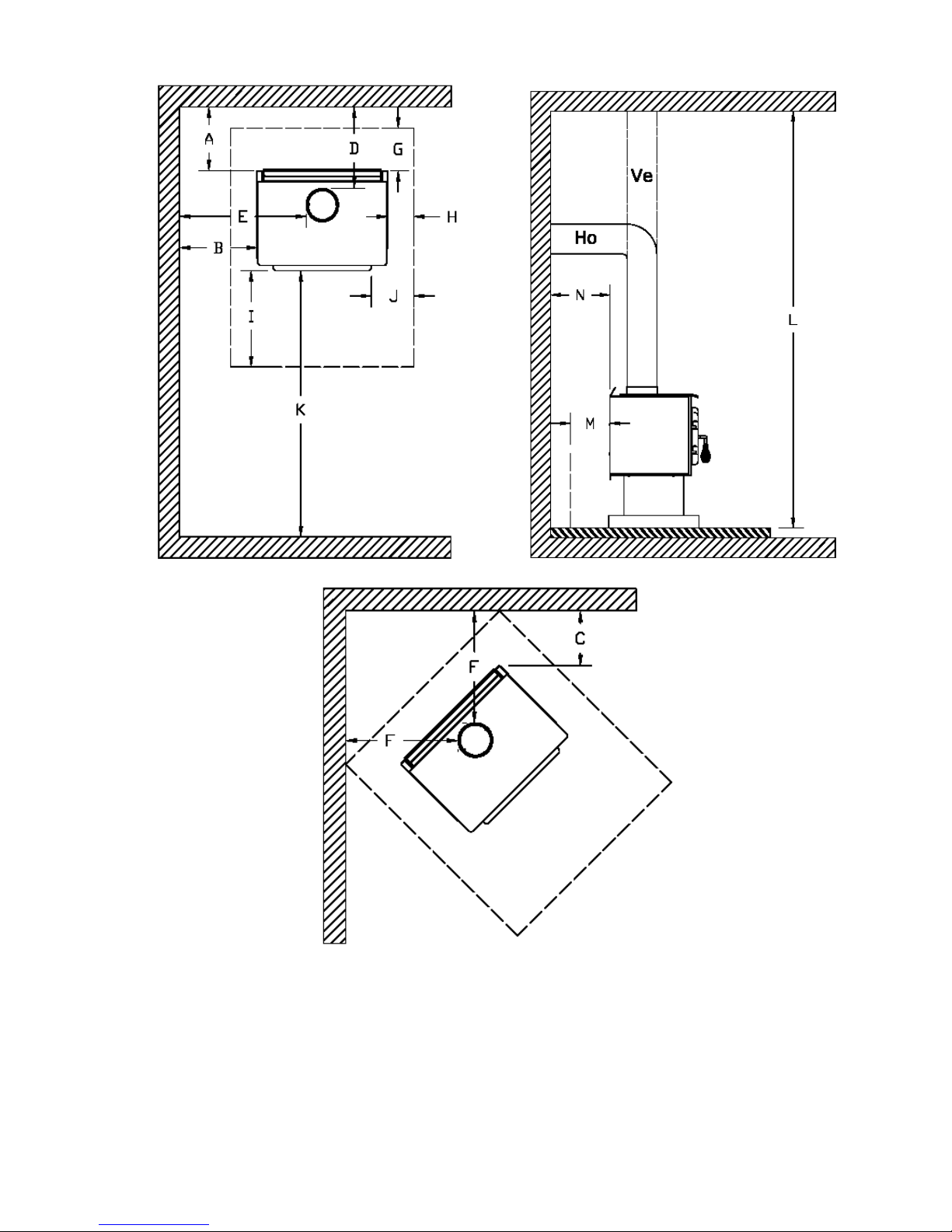
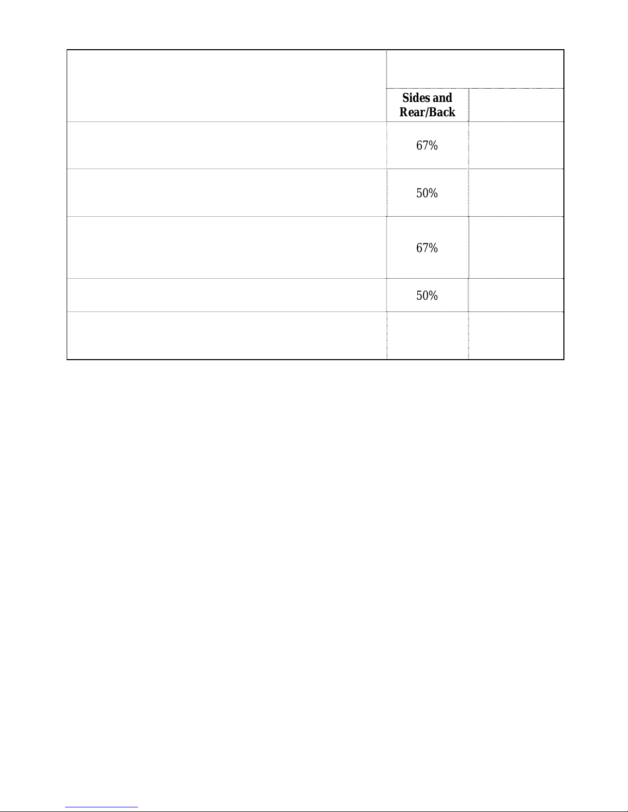
1.3CLEARANCES TO COMBUSTIBLES AND FLOOR PROTECTOR...................................................5
1.4DOOR OVERLAY INSTALLATION.......................................................................................................12
1.5MANUFACTURED (MOBILE) HOME INSTALLATIONS – ADDITIONAL REQUIREMENTS..13
SECTION 2.0 CHIMNEY (FLUE SYSTEM) ....................................................................................... 14
2.1DEFINITIONS.............................................................................................................................................14
2.2CHIMNEY...................................................................................................................................................14
2.2.1Step by step installation of your factory-built chimney........................................................................16
2.2.2Typical installation through an existing masonry chimney..................................................................24
2.3CHIMNEY CONNECTOR ........................................................................................................................27
2.4DRAFT.........................................................................................................................................................29
2.5OUTSIDE COMBUSTION AIR................................................................................................................29
2.6THE BENEFITS OF YOUR BLOWER (FAN)........................................................................................30
SECTION 3.0OPERATION............................................................................................................. 31
3.1SAFETY INFORMATION.........................................................................................................................31
3.2FUEL............................................................................................................................................................32
3.2.1The use of manufactured logs...............................................................................................................33
3.2.2Simple wood moisture test....................................................................................................................34
3.3NOTES ABOUT FIRST FIRING..............................................................................................................34
3.4LIGHTING A FIRE....................................................................................................................................34
3.5MAINTAINING THE FIRE ......................................................................................................................35
3.6FAN (BLOWER) OPERATION................................................................................................................35
SECTION 4.0MAINTENANCE...................................................................................................... 36
4.1CLEANING AND PAINTING YOUR STOVE........................................................................................36
4.2GLASS..........................................................................................................................................................36
4.3GASKETING...............................................................................................................................................36
4.4ASH REMOVAL USING THE ASH DRAWER......................................................................................37
4.5CHIMNEY (FLUE) CLEANING...............................................................................................................38
OSBURN LIMITED LIFETIME WARRANTY ................................................................................... 39

3
TECHNICAL SPECIFICATIONS
Maximum recommended heating area: Up to 1500 sq. ft.
Heating capacity* – BTU/hr., EPA test wood:
Heating capacity* – BTU/hr., seasoned cordwood: 44,000 BTU
55 000 BTU
Optimum efficiency: 85%
Average emissions (EPA): 7.5 g/hr.
Paint finish : Metallic black
Flue outlet (spigot) diameter : 6” (152 mm)
Maximum Log Length : 19’’ (483 mm)
Overall dimensions (W x D x H):
25½’’ x 20½’’ x 27½’’
(648 x 521 x 699 mm)
Firebox dimensions (W x D):
Firebox volume:
20’’ x 12½’’
(508 x 318mm)
1.5 cubic feet
(0,04 m3)
Door opening (W x H) :
18¼’’ x 7’’
(464x 178mm)
Weight: 300 lbs (137 kg)
*Why is the BTU indicated on the EPA label smaller than the one advertised?
You will notice a difference between the BTU output as indicated on the unit’s white EPA label affixed to the glass and the BTU as
advertised on our web site and/or product literature. The maximum BTU output we advertise for this unit is what will be obtained
with a full load of seasoned cordwood inserted inside the firebox. The EPA output, on the other hand, is what has been obtained
during emissions testing. The EPA test procedure requires that a special type of wood be used and positioned inside the firebox in a
manner that does not represent the way the firebox volume would normally be utilized using seasoned cordwood. The EPA test load
is typically much smaller. Hence, the BTU as per the EPA label is reduced. The BTU output that should be considered by anormal
user is the one we advertise for seasoned cordwood.

4
SECTION 1.0 - INSTALLATION
When installed and operated as described in these instructions, the Osburn 1500 wood stove is suitable for
use as a freestanding wood stove in residential installations. The Osburn 1500 wood stove is not intended for
installation in a bedroom.
In Canada, the CSA B365 Installation Code for Solid Fuel Burning Appliances and Equipment and the CSA
C22.1 Canadian National Electrical Code are to be followed in the absence of local code requirements. In the
USA, the ANSI NFPA 70 National Electrical Code and NFPA 211 Standard for Chimneys, Fireplaces, Vents
and Solid Fuel-Burning Appliances are to be followed in the absence of local code requirements.
In addition to the national installation and/or local building codes, fire officials (or other authorities having
jurisdiction) should be contacted to determine what restrictions and installation requirements might apply
locally.
Note that this heating unit must serve as a supplementary heat source. An alternate heat source should be
available in the home if needed. The manufacturer cannot be responsible for additional heating costs
associated with the use of an alternative heat source. It is highly recommended that the user buys this product
from a retailer who can provide installation and maintenance advices.
1.1 GENERAL INSTALLATION
CAUTION:
MIXING OF APPLIANCE OR FLUE SYSTEM COMPONENTS FROM DIFFERENT SOURCES OR MODIFYING THE
DIMENSIONAL SPECIFICATION OF COMPONENTS MAY RESULT IN HAZARDOUS CONDITIONS.WHERE SUCH
ACTION IS CONSIDERED,THE MANUFACTURER SHOULD BE CONSULTED IN THE FIRST INSTANCE.
DO NOT CONNECT THIS UNIT TO ANY AIR DISTRIBUTION SYSTEM.
CRACKED AND BROKEN COMPONENTS,e.g. GLASS PANELS OR CERAMIC TILES,MAY RENDER THIS
INSTALLATION UNSAFE.
ASOURCE OF FRESH AIR INTO THE ROOM OR SPACE HEATED SHALL BE PROVIDED WHEN REQUIRED.
CONNECTTHESTOVE ONLYTO ALINED MASONRYCHIMNEYCONFORMINGTONATIONALANDLOCALBUILDING
CODES FOR USE WITH SOLID FUEL,OR TO A LISTED FACTORY BUILT CHIMNEY SUITABLE FOR USE WITH SOLID
FUEL.
1.2 POSITIONING THE STOVE
It is very important to position the wood stove in an area that will favour the most efficient heat distribution
throughout the house. The stove should therefore be installed in the room where the most time is spent, and
in the most spacious room possible. Recall that wood stoves produce radiating heat, the heat we feel when we
are close to a wood stove. A wood stove also functions by convection, that is through the displacement of hot
air accelerated upwards and its replacement with cooler air at the floor level. The stove’s convection effect is
facilitated by the installation of a blower.

5
1.3 CLEARANCES TO COMBUSTIBLES AND FLOOR PROTECTOR
To install your appliance correctly, it is extremely important to respect all clearances to any combustibles as
indicated on your stove’s certification label.
Clearances to combustible materials
(see figure 1.3 to match each letter to a clearance)
CLEARANCES (SINGLE WALL PIPE)
CANADA USA
A 15" (381 mm) 15" (381 mm)
B 12" (305 mm) 12" (305 mm)
C 10" (254 mm) 10" (254 mm)
D 19" (483 mm) 19" (483 mm)
E 22" (559 mm) 22" (559 mm)
F 19" (483 mm) 19" (483 mm)
K 48" (1220 mm) 48" (1220 mm)
L 84" (213 cm) 84" (213 cm)
CLEARANCES (DOUBLE WALL PIPE)
CANADA USA
A 5" (127 mm) 5" (127 mm)
B 12" (305 mm) 12" (305 mm)
C 8" (203 mm) 8" (203 mm)
D 9" (229 mm) 9" (229 mm)
E 22" (559 mm) 22" (559 mm)
F 17" (432 mm) 17" (432 mm)
K 48" (1220 mm) 48" (1220 mm)
L 84" (213 cm) 84" (213 cm)

6
FIGURE 1.3 Clearances to combustible materials and floor protection

7
Floor protector
If the stove is to be installed on top of a combustible floor, it must be guarded by a non combustible material
as shown on figure 1.3 (see the dotted line area).
FLOOR PROTECTOR*
CANADA USA
G 8’’ (203 mm) – Note 1 N/A (Canada only)
H 8’’ (203 mm) N/A (Canada only)
I 18’’ (457 mm)
From door opening 16’’ (406 mm)
From door opening
J N/A (USA only) 8’’ (203 mm)
M 8’’ (203 mm) N/A (Canada only)
N N/A (USA only) Note 2
*Steel with a minimum thickness of 0.015’’ (0.38 mm) or ceramic tiles sealed together with grout. No
protection is required if the unit is installed on a non-combustible floor (ex: concrete).
Note 1 : The floor protection at the back of the stove is limited to the stove’s required clearance if such
clearance is smaller than 8 inches (203 mm).
Note 2 : Only required under the horizontal section of the connector. Must exceed each side of the
connector by at least 2 inches (51 mm).
Reduced clearances using shielding
You may decrease the clearances by installing heat radiation shields between the walls or the ceiling and the
stove. These heat radiation shields must be installed permanently, and can include sheet metal, a rigid non-
combustible sheet or a masonry wall.
Clearances of not less than 1" (25 mm) and not more than 3" (76 mm) between the bottom of the shield and
the floor and not less than 3" (76 mm) between the top ofthe shield and the ceiling must be respected to allow
vertical air circulation behind the shield. The shield must extend 20" (500 mm) above the stove top and 18"
(450mm) to each side of the stove (see graphic 1).
Following the installation of such a heat radiation shield, the clearances mentioned on the stove certification
plate may be reduced as stated in the following table.

8
TYPE OF PROTECTION
Reducing Clearances With
Shielding
Sides and
Rear/Back Top
Sheet metal, a minimum of 0,024" (0,61mm) spaced out at
least 1" (25mm) by non-combustible spacers (see
graphic 2). 67% 50%
Ceramic tiles, or an equivalent non-combustible material on
fire-proof supports spaced out at least 1" (25 mm) by non-
combustible spacers (see graphic 3). 50% 33%
Ceramic tiles, or an equivalent non-combustible material on
fire-proof supports with a minimum of 0,024" (0,61 mm) sheet
metal backing spaced out at least 1" (25 mm) by non-
combustible spacers (see graphic 4)
67% 50%
Brick spaced out at least 1" (25 mm) by non-combustible
spacers (see graphic 5) 50% N/A
Brick with a minimum of 0,024" (0,61 mm) sheet metal
backing spaced out at least 1" (25 mm) by non-combustible
spacers (see graphic 6). 67% N/A

9
Graphic 1
A- Minimum clearance required between the appliance and an unshielded combustible ceiling.
B- 20 in. (500 mm) minimum;
C- 1 in. (25 mm) minimum;
D- Between 1 in. and 3 in. (25 mm and 75 mm);
E- 3 in.(75 mm) minimum;
F- 18 in. (457 mm) minimum.
1- Shielding;
2- Non-combustible spacers;
3- Ceiling protector;
4- Combustible wall;
5- Ceiling;
6- Appliance (side view);
7- Appliance (top view).

10
Graphic 2
A- 1 in.(25 mm) minimum;
1- Combustible wall;
2- Non-combustible spacers;
3- 0.024’’ (0.61mm) sheet metal.
Graphic 3
A- 1 in. (25 mm) minimum;
1- Combustible wall;
2- Non-combustible spacers;
3- Non-combustible support;
4- Ceramic tile or non-combustible material.
Graphic 4
A- 1 in. (25 mm) minimum;
1- Combustible wall;
2- Non-combustible spacer;
3- 0.024’’ (0.61 mm) thick sheet metal;
4- Non-combustible support;
5- Ceramic tile or non-combustible material.

11
Graphic 5
A- 1 in. (25 mm) minimum;
1- Combustible wall;
2- Non-combustible spacers;
3- Brick.
Graphique 6
A- 1 in. (25 mm) minimum;
1- Combustible wall;
2- Non-combustible spacers;
3- 0.024’’ (0.61 mm) thick sheet metal;
4- Brick.

12
1.4 DOOR OVERLAY INSTALLATION
1- Remove the door from the stove and pass the handle through the hole of the overlay (see picture 1).
Picture 1
2- Flip over both parts with the finished side on a plane and smooth surface free from dirt to avoid any
scratchesAlign the holes of the door to those of the overlay. Fix the overlay with the 4 screws provided with
the owner’s manual and put the door back on its hinges (see picture 1).

13
1.5 MANUFACTURED (MOBILE) HOME INSTALLATIONS – ADDITIONAL
REQUIREMENTS
1. The stove must be bolted to the floor (secure the unit by prying out the two plastic plugs in the
pedestal, and installing the two 3/8" x 3-1/2" (9.8mm x 88.9mm) lag bolts through the holes
provided).
2. The unit must be provided with outside combustion air. Consult your Osburn dealer for
information about genuine parts needed for mobile home installations (genuine part numbers
#AC02080 & AC02090). See pictures below for reference.
3. Clearance from the top of stove to an unprotected ceiling should be a minimum of
52” (1321mm).
Note: For manufactured home installations in the USA, the stove must be grounded to the frame of
the home using a # 8 ground wire with approved terminations and star lock washers.
CAUTION : THESTRUCTUREINTEGRITYOFTHEMANUFACTURED(MOBILE) HOME
FLOOR, WALL, CEILING /ROOF MUST BE MAINTAINED.
WARNING : DO NOT INSTALL IN A SLEEPING ROOM.
Osburn Adapter for
fresh air kit – Genuine
part #AC02080
Insulated pipe for fresh
air kit – Genuine part
#AC02090

14
SECTION 2.0 CHIMNEY (FLUE SYSTEM)
2.1 DEFINITIONS
For clarity, the following definitions should be used with respect to these instructions:
A chimney system consists of a connector off the top of the stove, and a chimney, which attaches to
the connector and terminates outside the house.
A chimney can be a masonry chimney (of masonry construction with an inside liner), or a factory
built chimney.
A factory built chimney can be a double walled chimney (two concentric pipes with insulation -
sometimes referred to as an insulated solid pack) or an air cooled chimney (three concentric pipes,
with insulation between the first and second pipes, and air between the second and third pipes).
A single walled connector is a single pipe.
A double walled connector has two concentric pipes, no insulation, and is an air cooled connector.
2.2 CHIMNEY
CAUTION:
DONOTFILLANY FRAMEDSPACEAROUND THE FACTORY-BUILTCHIMNEY WITH
INSULATION OR ANY OTHER MATERIAL. INSULATION PLACED IN THIS AREA
COULD CAUSE ADJACENT COMBUSTIBLES TO OVERHEAT.
DO NOT USE MAKESHIFT COMPROMISES DURING INSTALLATION AS THEY MAY
BE SAFETY HAZARDS, AND A FIRE COULD RESULT.
DO NOT CONNECT THIS UNIT TO A CHIMNEY SYSTEM SERVING ANOTHER
APPLIANCE.
DO NOT CUT RAFTER OR CEILING JOISTS WITHOUT FIRST CONSULTIN A
BUILDING OFFICIAL TO ENSURE STRUCTURAL INTEGRITY IS NOT
COMPROMISED.
Your wood stove may be hooked up with a factory built or masonry chimney. If you are using a factory built
chimney, it must comply with UL103 (USA) or ULCS629 (Canada) standards. It must therefore be a 6”
(152mm) HT Type (2100°F) chimney. It is extremely important that it be installed according to the
manufacturer's specifications. The manufacturers’ installation instructions and specified clearances should
always be followed in accordance with local and national installation codes. In Canada the CSA B365 and the
CSA C22.1 installation codes are to be followed. In the USA the ANSI NFPA 70 and ANSI NFPA 211
installation codes are to be followed.

15
If you are using a masonry chimney, it is important that it be built in compliance with the specifications of the
Building Code. It must be lined with fire clay bricks, or clay tiles, sealed together with fire cement, or havea
code-approved solid fuel burning stainless steel liner. Round chimneys are the most efficient.
The interior diameter of the chimney should be identical to the stove's smoke exhaust. A chimney which is
too small may cause draft problems, since it may not have the required volume to properly evacuate the
quantity of smoke resulting from the combustion. A chimney whish is too large may also cause draft
problems. In fact, a large chimney will be harder towarm-up and may not reach high enough temperatures to
create a proper draft effect. Note that it is the chimney which creates the draft effect, not your stove.
Your stove's performance is therefore directly dependent on an adequate draft from your chimney.
The following recommendations may be useful for the installation of your chimney:
Do not connect your stove to a chimney serving another appliance.
The chimney must rise above the roof at least 3' (0.9 mm) from the uppermost point of contact. See
Figure 2.2.
The chimney must exceed any part of the buildingor other obstruction within a 10' (3.04 m) distance
by a height of at least 2' (0.6 m). See Figure 2.2.
The minimum overall height of the chimney system, measured from the stove top to the exterior
termination cap of the chimney should be at least 12'(3.66m). A chimney which is too short may lack
the “tunnel effect” required to obtain a proper draft.
Installation of an interior chimney is always preferable to an exterior chimney. Chimneys constructed
outside of the home on an exterior wall should be avoided if possible, especially in colder climates.
The gas which circulates into an interior chimney will cool more slowly, thus reducing the build-up
of creosote and the risk of flue fires.
All else being equal, cooler chimneys will have less draft than hotter ones. This problem will be
amplified if the chimney is excessively long. A chimney which is excessively long may be very hard
to warm-up due to its higher volume. A cool chimney may even down draft (reverse flow) due to the
difficulty in heating it up to operating temperature while trying to evacuate the stack gases.
If an exterior chimney is used, the best results will be obtained by using a connector vertically off the
unit to the highest possible point before elbowing off horizontally to the exterior chimney. For
efficiency and safety reasons the stove must not be installed with an insulated chimney connected
directly to the appliance.
Using a fire screen at the extremity of the chimneyrequires regular inspection in order to insure that it
is not obstructed, thus blocking the draft. It should be cleaned when necessary.

16
FIGURE 2.2 Minimum Height of the Chimney
2.2.1 Step by step installation of your factory-built chimney
Thewaytoinstallyourchimneymayvaryfromonechimneymanufacturertoanother.Theinstructions
contained in this manual are based on the recommendations of chimney manufacturers whose
products are sold at many North American retailers of wood stoves and related heating accessories.
Wall support system
If your chimney must rise along an outside wall, you need to connect it to your stove through an
adjacent wall. For this type of installation, the following items are normally required :
Chimney
Suitable lengths of chimney (enough to go up to your roof)
An adjustable wall support
A wall thimble
Anadequatenumber ofwallbands(oneforevery8feetofchimney,excludingtheroofportion)
A stove pipe adapter
One insulated tee & plug
A roof flashing kit (if necessary)
A chimney cap.
Roof guys (if required)
Stove pipe
An adequate number of stove pipe sections (24 gauge)
A 90o elbow
Typical installation through the wall

17
FIGURE 2.2.1 (A) Typical installation through the wall
1- Start by positioning your stove where you would like it to go, taking into account the minimum
clearancesto combustiblematerial. You will thenbeableto determinewhere the chimney will
pass through the wall. You will probably have to adjust the stove position slightly to ensure
that your chimney will run between the studs. You can use a stud finder to locate the studs.
Use a spoke saw or jig saw to cut a hole, remembering that you need to maintain a clearance
of 2 inches between the chimney and any combustible materials. For concrete walls, cut a
hole slightly larger than the outer diameter of the chimney.

18
2- Once the opening completed, you need to frame in the area to allow for the installation of a
wall thimble. A wall thimble is not required for installations through concrete walls.
3- You must first secure the wall thimble into the exterior wall surface. Then, do the same inside
and fasten the trim plate.
4- Then, from outsidethe building, slide ashortchimney length (attachedtothetee) through the
wallthimble.The chimney must extendatleast 3 inchesintotheliving space where itattaches
to the stove pipe.
5- You can now install the wall support. Simply slide the wall support up to the tee, ensuring that
the adapter on the support engages with the female coupler on the bottom of the tee. When
the wall support is level and properly positioned,you canuse lag boltstosecure it intothewall
studs. To complete the installation, install an insulated tee plug below the wall support.

19
6- You can start to add chimney sections. We recommend that you also use locking bands to
secure all connections. You will need to secure the chimney to the house using wall bands.
Wall bands wrap around the chimney and then attach to the wall. Install the first one 3 feet
abovethewall support. Then, you willneedanother band foreach8feetofchimney. Note: if
your chimney must be installed through your soffit, install a roof flashing above and
finishing plate below where the roof is cut. Consult the following section called
“CEILING SUPPORT SYSTEM” for more details.
7- Authorities require that the chimney extend not less than 3 feet above thehighest pointwhere
it passes through the roof of a building and not less than 2 feet above any portion of the
buildingwithin10 feet. If the chimneyextendsmore than 5 feetabovethe roof deck, roofguys
with telescoping legs and draw bands are required.
8- Finally, twist on your rain cap and you can head back inside.
Other manuals for 1500
1
Table of contents
Other Osburn Wood Stove manuals

Osburn
Osburn 1700 User manual

Osburn
Osburn OB00900 User manual

Osburn
Osburn OB01613 User manual

Osburn
Osburn 2300 User manual

Osburn
Osburn Matrix Insert OB02028 User manual

Osburn
Osburn 2000 User manual

Osburn
Osburn MATRIX 1900 User manual

Osburn
Osburn MATRIX OB02022 User manual

Osburn
Osburn 1600 User manual

Osburn
Osburn 1600 User manual