oscilloquartz OSA 5240 User manual

OSA 5240 - User Manual - Revision P - June 2009
OSA 5240
Telecom GPS Receiver
USER MANUAL
Model 945.524.0xx

OSA 5240 - User Manual - Revision P - June 2009 ii
This page has been intentionally left blank

OSA 5240 - User Manual - Revision P - June 2009 iii
What's new in this revision
Correct IRIG-B card codes

OSA 5240 - User Manual - Revision P - June 2009 iv
This page has been intentionally left blank

Contents
OSA 5240 - User Manual - Revision P - June 2009 v
Table of Contents Page
1. INTRODUCTION .................................................................................................................1-1
1.1 About this Manual ..................................................................................................1-3
1.1.1 Copyright Notice .........................................................................................1-3
1.2 Reading Guide........................................................................................................1-4
1.3 Safety Instructions.................................................................................................1-5
1.4 Warranty..................................................................................................................1-8
1.5 Certification ............................................................................................................1-9
2. PRODUCT OVERVIEW.....................................................................................................2-11
2.1 Introduction ..........................................................................................................2-13
2.2 Reliability ..............................................................................................................2-13
2.3 Bridging ................................................................................................................2-13
2.4 Signal Quality .......................................................................................................2-13
2.5 Output Configurations .........................................................................................2-13
2.6 Versatility..............................................................................................................2-14
2.7 Management .........................................................................................................2-14
2.7.1 Local.........................................................................................................2-14
2.7.2 Remote.....................................................................................................2-14
3. MAIN FUNCTIONS..............................................................................................................3-1
3.1 System Architecture...............................................................................................3-3
3.2 Frequency Generation............................................................................................3-5
3.2.1 Reference Input Selection...........................................................................3-5
3.2.2 Phase Build-out ..........................................................................................3-5
3.2.3 Filtering and Bridging Capability..................................................................3-6
3.3 Synchronization Outputs.......................................................................................3-7
3.3.1 SSM............................................................................................................3-7
3.3.2 Output Squelch...........................................................................................3-8
3.3.3 Re-Timing Channels ...................................................................................3-9
3.4 Timecode Output..................................................................................................3-10
3.4.1 NTP Server...............................................................................................3-10
3.4.2 IRIG-B Outputs .........................................................................................3-10
3.5 Monitoring & Alarms ............................................................................................3-10
3.6 Power Supply Inputs............................................................................................3-11
4. EQUIPMENT DESCRIPTION..............................................................................................4-1
4.1 Dimensional Views.................................................................................................4-3

Contents
OSA 5240 - User Manual - Revision P - June 2009 vi
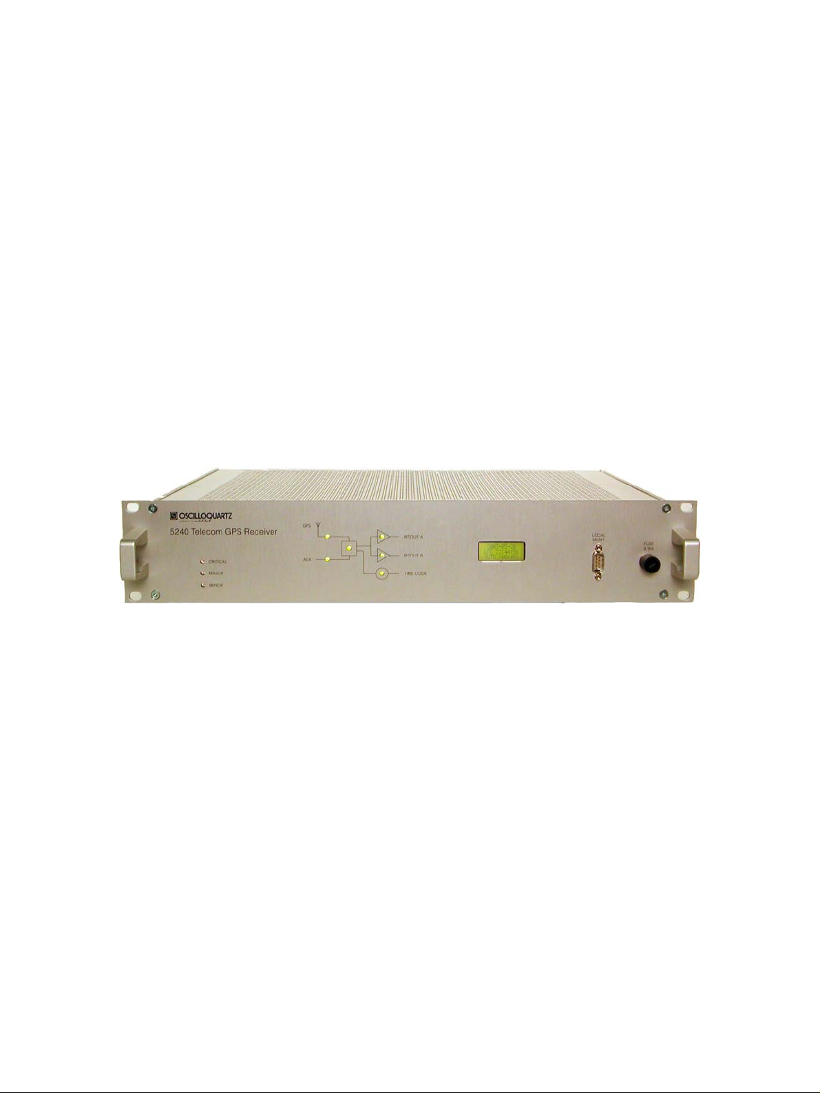
4.1.1 Front view ...................................................................................................4-3
4.1.2 Top View.....................................................................................................4-3
4.2 Front Panel Description.........................................................................................4-4
4.2.1 E1...............................................................................................................4-4
4.2.2 T1 ...............................................................................................................4-4
4.3 Rear Panel Layout..................................................................................................4-9
4.3.1 Connectors Panel Layout (except Outputs Slots)........................................4-9
4.3.2 Outputs Slots – OSA 5240 r1.xE (E1 model).............................................4-10
4.3.3 Outputs Slots – OSA 5240 r1.xT (T1 model).............................................4-11
5. INSTALLATION ..................................................................................................................5-1
5.1 Unpacking and Inspection.....................................................................................5-3
5.2 Working Conditions ...............................................................................................5-4
5.3 Tools Required.......................................................................................................5-4
5.4 Power-Up ................................................................................................................5-5
5.4.1 Connections................................................................................................5-6
5.4.2 Warm-up.....................................................................................................5-8
5.5 Connecting the GPS Antenna................................................................................5-9
5.6 Connecting the Auxiliary Input Reference..........................................................5-10
5.6.1 Auxiliary Input Connection ........................................................................5-10
5.6.2 Timing Extractor – Passive (TEX-P)..........................................................5-12
5.7 Connecting the Output Signals ...........................................................................5-13
5.7.1 Output Connections ..................................................................................5-13
5.7.2 Output Connectors pin-out ........................................................................5-14
5.8 Time Code Output................................................................................................5-16
5.9 Alarm Contact Output Wire Wrap Adapter..........................................................5-16
6. CONFIGURING THE UNIT..................................................................................................6-1
6.1 Factory Default Parameters...................................................................................6-3
6.2 Configuration..........................................................................................................6-4
7. REMOTE OPERATIONS.....................................................................................................7-1
7.1 Features..................................................................................................................7-3
7.2 Electrical Alarm Outputs........................................................................................7-3
7.2.1 "ALARM OUTPUTS" Pin-out.......................................................................7-3
7.2.2 Wire-wrap adapter ......................................................................................7-4
7.3 Local Management Capabilities ............................................................................7-4
7.3.1 "RS-232C" Pin-out ......................................................................................7-5
7.4 Network Management Capabilities........................................................................7-6
7.4.1 Connecting to a SyncView™ Remote Manager ..........................................7-6
8. MAINTENANCE & TROUBLESHOOTING..........................................................................8-1
8.1 Preventive Maintenance.........................................................................................8-4

Contents
OSA 5240 - User Manual - Revision P - June 2009 vii
8.2 Checking the functional status of the OSA 5240 Telecom GPS Receiver..........8-4
8.2.1 Visual Status...............................................................................................8-4
8.2.2 Internal Status.............................................................................................8-4
8.3 Troubleshooting.....................................................................................................8-5
8.4 Oscilloquartz Contact Information ......................................................................8-11
8.4.1 Technical Assistance ................................................................................8-11
8.4.2 Sales ........................................................................................................8-12
9. SPECIFICATIONS...............................................................................................................9-1
9.1 Input Specifications ...............................................................................................9-3
9.2 Tracking Subsystem Characteristics....................................................................9-4
9.3 Output Specifications - OSA 5240 r1.xE ...............................................................9-5
9.4 Output Specifications - OSA 5240 r1.xT ...............................................................9-6
9.5 Time Code Outputs ................................................................................................9-7
9.6 Remote Functions..................................................................................................9-8
9.7 General Specifications...........................................................................................9-9
APPENDIX A : ORDERING INFORMATION.............................................................................. A-1
GLOSSARY......................................................................................................................................I
INDEX.............................................................................................................................................III
DOCUMENT HISTORY .................................................................................................................. V

List of Figures
OSA 5240 - User Manual - Revision P - June 2009 viii
List of Figures
Figure 3-1 System Architecture....................................................................................................3-3
Figure 3-2 Schematic presentation of the phase buildout.............................................................3-5
Figure 3-3 Example of filtering the GPS synchronization signal. ..................................................3-7
Figure 3-4 Block diagram of the Re-Timing Function. ..................................................................3-9
Figure 4-1 Dimensions - Front View.............................................................................................4-3
Figure 4-2 Dimensions - Top View ...............................................................................................4-3
Figure 4-3 Front Panel Description - example E1.........................................................................4-4
Figure 4-4 Front Panel Description - example T1.........................................................................4-4
Figure 4-5 Rear Connector Panel - example E1...........................................................................4-9
Figure 4-6 Rear Connector Panel - example T1...........................................................................4-9
Figure 4-7 Rear Output Slots - example model E1.....................................................................4-10
Figure 4-8 Rear Output Slots - example model T1 .....................................................................4-11
Figure 5-1 Rear Power Supplies DC Connection Location...........................................................5-6
Figure 5-2 Rear Power Supply AC Connection Location..............................................................5-6
Figure 5-3 DC Connection View...................................................................................................5-7
Figure 5-4 AC Connection View...................................................................................................5-8
Figure 5-5 Rear Unit Connection GPS Antenna Location.............................................................5-9
Figure 5-6 Rear Unit Connection AUX Inputs Location...............................................................5-10
Figure 5-7 BNC Aux Input Connector.........................................................................................5-11
Figure 5-8 Typical use of the TEX-P with the OSA 5240 Telecom GPS Receiver ......................5-12
Figure 5-9 Rear unit output signals ............................................................................................5-13
Figure 5-10 BNC Output Connectors .........................................................................................5-15
Figure 7-1 Alarm Output...............................................................................................................7-3
Figure 7-2 RS 232 for Local Management Port ............................................................................7-4
Figure 7-3 Remote Management Port..........................................................................................7-6
Figure 8-1 Remote Management Port.........................................................................................8-4

List of Tables
OSA 5240 - User Manual - Revision P - June 2009 ix
List of Tables
Table 3-1 Telecordia Recommendation GR-1244-CORE.............................................................3-6
Table 4-1 Operational / Alarm State– OSA 5240 r1.0E (E1 model) ..............................................4-5
Table 4-2 Operational / Alarm State– OSA 5240 r1.1E (E1 model) ..............................................4-6
Table 4-3 Operational / Alarm State– OSA 5240 r1.0T (T1 model) ..............................................4-7
Table 4-4 Operational / Alarm State– OSA 5240 r1.1T (T1 model) ..............................................4-8
Table 4-5 Rear Connectors Description .......................................................................................4-9
Table 4-6 E1 Outputs slot ..........................................................................................................4-10
Table 4-7 T1 Output slots...........................................................................................................4-11
Table 5-1 Voltage Range and Fuses............................................................................................5-6
Table 5-2 Aux Input Connector - BNC........................................................................................5-11
Table 5-3 AUX Input Connectors - Sub-D, Wire-wrap ................................................................5-12
Table 5-4 Sub-D Output connectors...........................................................................................5-14
Table 5-5 Wire-Wrap (2p) Output Connectors............................................................................5-14
Table 5-6 Sub-D RS422 Output connectors...............................................................................5-15
Table 5-7 Wire-Wrap (3p) Output connectors.............................................................................5-15
Table 5-8 BNC Output connections............................................................................................5-15
Table 6-1 Factory default parameters ..........................................................................................6-3
Table 7-1 “Alarm output” Pin-out..................................................................................................7-3
Table 7-2 RS232 for Local Management Pinout...........................................................................7-5
Table 7-3 NULL MODEM cable....................................................................................................7-5
Table 8-1 Troubleshooting .........................................................................................................8-10
Table 9-1 Input specifications.......................................................................................................9-3
Table 9-2 Tracking SubSystem Characteristics............................................................................9-4
Table 9-3 Output Specifications r1.xE ..........................................................................................9-5
Table 9-4 Output Specifications r1.xT ..........................................................................................9-7
Table 9-5 Time Code Output Specifications.................................................................................9-7
Table 9-6 Remote Functions Specifications .................................................................................9-8
Table 9-7 General Specifications .................................................................................................9-9
Table 9-8 Ordering E1 Units ....................................................................................................... A-1
Table 9-9 Ordering T1 Units........................................................................................................ A-2
Table 9-10 Fuse Ordering Numbers............................................................................................ A-2
Table 9-11 Ordering Miscellaneous Accessories......................................................................... A-3

List of Procedures
OSA 5240 - User Manual - Revision P - June 2009 x
List of Procedures
Procedure 5-1 Auxiliary Input Connection ..................................................................................5-11
Procedure 5-2 Output Signal Connection...................................................................................5-13

Introduction
OSA 5240 - User Manual - Revision P - June 2009
1-2
This page has been intentionally left blank

Introduction
OSA 5240 - User Manual - Revision P - June 2009
1-3
1.1 About this Manual
This manual has been designed to provide basic and detailed information for the correct
use and operation of the OSA 5240. It summarizes the overall equipment concept and
theory of operation, describes the hardware itself and provides information related to
installation, operation and maintenance.
It is intended for the use of the following types of users:
Systems Engineers: An overview of the equipment concept and theory of
operation.
Installation Engineers: Detailed technical information and procedures for
correct installation, operation, configuration and
commissioning as well as equipment specifications
and maintenance guidelines.
Maintenance Engineers: Information on troubleshooting, maintenance and
equipment technical data.
1.1.1 Copyright Notice
Copyright © 2008 Oscilloquartz SA
All Rights Reserved
The Oscilloquartz product described in this book is furnished under a license
agreement and may be used only in accordance with the terms of the agreement.
The contents and information in this document are provided in connection with
Oscilloquartz products. No license, expressed or implied by estoppels or otherwise, to
any intellectual property rights is granted by this document. Except as provided in
Oscilloquartz SA’s Terms and Conditions of Sale for such products.
This document is exclusive property of Oscilloquartz SA and may not, in whole or in
part, be copied, photocopied, reproduced, modified, translated, reduced to any
electronic medium or machine-readable, stored in a retrieval system, or transmitted in
any form without prior consent in writing from Oscilloquartz SA, Brévards 16, 2002
Neuchâtel 2, Switzerland.
Every effort has been made to ensure the accuracy of this guide. However,
Oscilloquartz SA makes no warranties with respect to this documentation and
disclaims any implied warranties of merchantability and fitness for a particular
purpose. Oscilloquartz SA shall not be liable for any errors or for incidental or
consequential damages in connection with the furnishing, performance, or use of this
manual or the examples herein.
Oscilloquartz SA may make changes to specifications and product descriptions at any
time, without notice.

Introduction
OSA 5240 - User Manual - Revision P - June 2009
1-4
1.2 Reading Guide
Special icons, attracting your attention, precede important and/or critical information in this
document. Hereafter are explanations of each icon.
CAUTION
This symbol is extremely important and must not be neglected. It precedes
information or procedures regarding installation, operation or maintenance.
Follow all steps or procedures, as instructed, to avoid any damage to
equipment or serious personal injury.
ELECTRICAL SHOCK HARZARD
This warning symbol is extremely important and must not be neglected. It
indicates that there are dangerous high voltages present inside the
enclosure of this product and precedes important warnings to avoid any risk
of fire or electrical shock that could lead to serious personal injury or loss of
life.
ESD CAUTION
Electrostatic Discharge (ESD) must be avoided so as not to damage or
destroy static sensitive components.
Note:
A note symbol informs the reader that additional information on the related
subject is provided in order to simplify a described task, suggest other
references or even just simplify an explanation.
Recommendation:
Recommendations advise the user on manufacturer tested methods and
procedures proven valuable for correct use and optimum equipment results.

Introduction
OSA 5240 - User Manual - Revision P - June 2009
1-5
1.3 Safety Instructions
IMPORTANT SAFETY INSTRUCTIONS.
DO NOT DISCARD, READ BEFORE OPERATING
GENERAL
Exercise extreme care when handling any electronics equipment as it
contains precision parts that can be damaged by improper handling.
Avoid touching connector pin surfaces. Foreign matter deposited on contact
surfaces can cause corrosion, and eventually lead to degradation of
performance. In addition, do not use abrasives to clean contact/pin surfaces.
FIRE
For continued protection against risk of fire, ensure that only the specified
fuse type and rating are used. Fuse specifications are contained in this
previous section, and the label on the unit’s front panel.
ESD CAUTION
Electrostatic Discharge (ESD) must be avoided so as not to damage or
destroy static sensitive components in the OSA 5240. Please observe
proper ESD handling procedures. Use an approved anti-static bracelet in
accordance with company practice.
WATER AND MOISTURE
Do not place containers with liquids such as coffee, water, sodas, etc. on
this unit. Do not operate this equipment in a wet environment.
HEATING
Do not install this product near heat sources such as radiators, air ducts,
areas subject to direct, intense sunlight, or other products that produce heat.

Introduction
OSA 5240 - User Manual - Revision P - June 2009
1-6
VENTILATION
Slots and openings in the chassis are provided for ventilation and to ensure
reliable operation of the product. To protect the unit from overheating, those
openings must not be blocked or covered. When integrating this unit in a
rack cabinet, at least one inch (2.5 cm) of clearance above and below the
unit is necessary to assure sufficient cooling.
GROUNDING
EARTH CONNECTION IS ESSENTIAL BEFORE CONNECTING TO THE
SUPPLY.
The OSA 5240 shelf must be connected to Earth Ground (common bounding
network (DC-C)). The wire used for the connection must be a minimum of
AWG16.
Ensure that all other devices connected to the 5240, are connected to
protective (earth ground). (Grounding one conductor of a two-conductor
outlet is not sufficient.)
Any interruption of the protective (grounding) conductor (inside the
equipment) or disconnecting the protective earth terminal is likely to make
this equipment dangerous. Intentional interruption is prohibited.
POWER
Make sure the power sources are compatible with the power inputs of the
equipment. Verify that the correct fuses are installed. The equipment's
protective earth terminals must be connected to the protective conductor of
the (mains) power cord or the station earth. The mains plug shall only be
inserted in a socket outlet provided with a protective earth contact. The
protective action must not be negated by the use of an extension cord
(power cable) without a protective conductor (grounding).
Make sure that only fuses with the required rated current and of the specified
type (normal blow, time delay, etc.) are used for replacement. The use of
repaired fuses and the short-circuiting of fuse holders must be avoided.
Whenever it is likely that the protection offered by fuses has been impaired,
the equipment must be made inoperative and be secured against any
unintended operation

Introduction
OSA 5240 - User Manual - Revision P - June 2009
1-7
POWER CORD PROTECTION
The power supply cord for this product should be routed or installed in such
a manner to protect it from being walked on or pinched. The unit should be
powered down completely before connecting or disconnecting the power
cable. The power cord should be removed before moving the unit. The
power cord must be placed near an easily accessible unobstructed socket
outlet.
CLEANING
Connected and running equipment can only be dusted using a soft dry cloth.
ONLY WITH, AUTHORIZED PERMISSION, OUT OF SERVICE &
UNPLUGGED equipment can be cleaned with a soft cloth slightly moistened
with a mild detergent solution. Do not use liquid cleaners, aerosols, abrasive
pads, scouring powders or solvents, such as benzine or alcohol. Ensure the
surface cleaned is fully dry before reconnecting power.
SERVICING AND MODIFICATIONS
To avoid dangerous electric shock, do not perform any servicing or
modifications other than what is recommended in this User Manual. Do not
attempt to gain access to areas of the unit where dangerous voltages are
present. Refer servicing to qualified service personnel.
DAMAGE REQUIRING SERVICE
•Refer servicing to qualified service personnel under the following
conditions:
•When the power supply cord is damaged.
•If liquid has been spilled into the enclosure of the unit.
•If the product does not function normally by following the instructions
in the User’s Manual. Adjust only those controls that are covered by
the operating instructions. Improper adjustment of other controls may
result in damage and will often require rework by a qualified
technician to restore the product to its normal operation.
•If the product has been damaged in any way.
When the unit displays a negative, distinct change in performance.

Introduction
OSA 5240 - User Manual - Revision P - June 2009
1-8
1.4 Warranty
This Oscilloquartz product carries a warranty which commences from date of dispatch
from factory. Unless agreed otherwise or stipulated differently on the original
acknowledgement of order, the duration of the warranty is twenty four months.
It applies to demonstrably faulty material or poor workmanship, but excludes batteries.
Oscilloquartz shall bear only the cost of repair or replacement in its own premises. Should
this not be possible for reasons beyond our control, all additional costs are at customer
expense.
Repairs under warranty carry either the balance of the original warranty or a six months
warranty, whichever is longer.
Damages resulting from natural wear, improper maintenance, failure to observe the
operating instructions, excessive strain, unsuited consumption material as well as
improper environmental and mounting conditions are excluded from this warranty.
The warranty expires if the customer or a third party modifies or repairs the product
without Oscilloquartz's prior written consent or if the customer does not take immediate
steps to prevent the damage from becoming more serious; likewise, if insufficient time is
provided for repair or replacement.
The customer will not be entitled to other warranty claims. Oscilloquartz is not liable for
consequential damage.

Introduction
OSA 5240 - User Manual - Revision P - June 2009
1-9
1.5 Certification
EQUIPMENT CERTIFICATION:
Oscilloquartz equipment is tested according to well-defined procedures. Appropriate
testing and inspection takes place at the component, board, equipment and system levels.
The company maintains in-house cesium standards that are continuously compared to
UTC. Before any equipment is released, it must satisfy the relevant tests and inspection
schedules. The equipment is then issued with a "Certificate of Conformity" that
guarantees its conformance with the relevant performance criteria.
The OSA 5240 GPS is designed to be compliant to:
•NEBS level 3
•FCC (in progress)
•EMC : EN50081-1, EN50082-1
•SAFETY : EN60950
A variety of Oscilloquartz products are certified world-wide. For details, please refer to our
web site at www.oscilloquartz.com
COMPANY CERTIFICATION:
•Certified since 1998 by the Swiss Accreditation Service and Swiss Federal
Office of Metrology as an accredited laboratory for time and frequency.
•Certified ISO 9001 since 1994 and ISO 14001 since 2000 by The Swiss
Association for Quality and Management Systems (SQS)

Introduction
OSA 5240 - User Manual - Revision P - June 2009
1-10
This page has been intentionally left blank
Table of contents