OSEE VAC6840N User manual

VAC6840N
Video & Audio 2X1 Switcher
USER MANUAL


Product Information
Model: VAC6840N Video & Audio 2X1 Switcher
Version: V010001
Release Date: February 24th, 2009
Company
OSEE TECHNOLOGY CO., LTD.
Contact Information
Address: No.22 Building, No.68 zone, Beiqing Road, Haidian District,
Beijing, China
Post Code: 100094
Tel: (+86) 010-62434168
Fax: (+86) 010-62434169
Web: http://www.osee-dig.com/
E-mail: [email protected]

Contents
Chapter 1 Introduction ..................................................................................................1
1.1 Product Overview ............................................................................................................................1
1.2 Features ............................................................................................................................................1
1.3 Module Descriptions ........................................................................................................................2
1.3.1 6800-C2 Frame Back Panel Connector ................................................................................. 2
1.3.2 VAC6840N Module Back Connector.................................................................................... 2
1.3.3 Signal Flow ...........................................................................................................................3
Chapter 2 Installation....................................................................................................3
2.1 Maximum Power Ratings for Frame................................................................................................3
2.2 Unpacking the Module.....................................................................................................................4
2.2.1 Preparing the Product for Installation ...................................................................................4
2.2.2 Check the Packing List..........................................................................................................4
2.3 Installing the Module .......................................................................................................................4
2.4 Making the Connections ..................................................................................................................5
2.5 Removing the Module......................................................................................................................5
Chapter 3 Operation and Control....................................................................................6
3.1 Switches and Key.............................................................................................................................6
3.2 Bank Selection .................................................................................................................................6
3.3 Description of LED Indicator...........................................................................................................9
Chapter 4 Specifications................................................................................................9
4.1 Analog Composite Video .................................................................................................................9
4.2 Analog Audio .................................................................................................................................10
4.3 Power consumption........................................................................................................................10
Chapter 5 Warranty for osee product....................................................................... 11
5.1 What the warranty covers:.............................................................................................................. 11
5.2 What the warranty does not cover:................................................................................................. 11

VAC6840N Video & Audio 2X1 Switcher Operating Manual
Specifications are subject to change without notice. —1—
Chapter 1 Introduction
1.1 Product Overview
VAC6840N is an analog changeover. The changeover is performed by the relays on VAC6840N rear
panel. Selected signal at the output is maintained when power failure. The input can be selected
automatically or manually. Automatic signal selection is based on video signal presence and video
level detection. An optional remote control panel can be chosen for manual control.
VAC6840N video & audio 2X1 switcher can be controlled by the switcher on the front panel.
The module can be installed in 6800N series frame.
Tab. 1-1 Description of VAC6840N Switcher
Module Description
VAC6840N
2 channels analog composite video signal inputs, 2 channels analog
stereo audio signal inputs;
1 channel analog composite video signal output, 1 channel analog
audio signal output.
1.2 Features
The VAC6840N offers the following features:
Support NTSC/PAL inputs
Relay switching can maintain selected input on power loss
Automatic mode based on video signal presence and video level detection
FCC Caution:
Any Changes or modifications not expressly approved by the party responsible for compliance could
void the user's authority to operate the equipment.
This device complies with part 15 of the FCC Rules.
Operation is subject to the following two conditions: (1) This device may not cause harmful interference,

VAC6840N Video & Audio 2X1 Switcher Operating Manual
Specifications are subject to change without notice. —2—
and (2) this device must accept any interference received, including interference that may cause
undesired operation.
Note: This equipment has been tested and found to comply with the limits for a Class B digital device,
pursuant to part 15 of the FCC Rules. These limits are designed to provide reasonable protection against
harmful interference in a residential installation. This equipment generates uses and can radiate radio
frequency energy and, if not installed and used in accordance with the instructions, may cause harmful
interference to radio communications. However, there is no guarantee that interference will not occur in
a particular installation. If this equipment does cause harmful interference to radio or television
reception, which can be determined by turning the equipment off and on, the user is encouraged to try to
correct the interference by one or more of the following measures:
Reorient or relocate the receiving antenna.
Increase the separation between the equipment and receiver.
Connect the equipment into an outlet on a circuit different from that to which the receiver is connected.
Consult the dealer or an experienced radio/TV technician for help.
1.3 Module Descriptions
1.3.1 6800-C2 Frame Back Panel Connector
Fig.1-1 Back Connector of 6800-C2 frame
1.3.2 VAC6840N Module Back Connector
Fig.1-2 Back Connector of VAC6840N
VAC6840N Video & Audio 2X1 Switcher Operating Manual
Specifications are subject to change without notice. —3—
Tab. 1-2 Description of VAC6840N Back Connector
Position Description
AIN 1A Analog audio signal input terminal 1A.
AIN 1B Analog audio signal input terminal 1B.
AIN 2A Analog audio signal input terminal 2A.
AIN 2B Analog audio signal input terminal 2B.
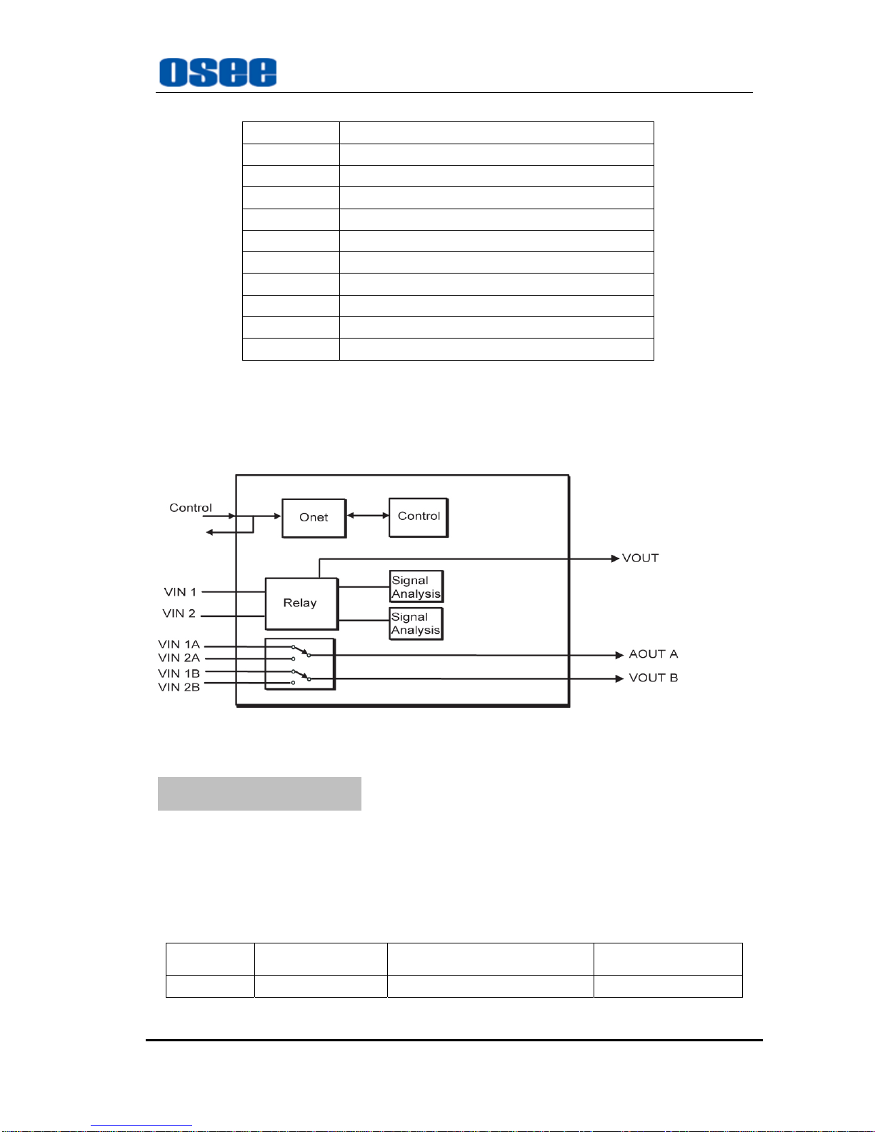
AOUT A Analog audio signal output terminal A.
AOUT B Analog audio signal output terminal B.
VIN 1 Analog composite video signal input terminal 1.
VIN 2 Analog composite video signal input terminal 2.
VOUT Analog composite video signal output terminal
ONET Switch control signal input and output
1.3.3 Signal Flow
Fig. 1-3 Signal Flow of VAC6840N
Chapter 2 Installation
2.1 Maximum Power Ratings for Frame
The maximum power ratings that different types of frames can sustain are listed in the Table 2-1
Tab. 2-1 Maximum Power Consumption
Frame Maximum Voltage Redundant Power Supplies Numbers of Slots
6800N-C2 60W Yes 10

VAC6840N Video & Audio 2X1 Switcher Operating Manual
Specifications are subject to change without notice. —4—
2.2 Unpacking the Module
2.2.1 Preparing the Product for Installation
Contact your dealer right now if any items are missing.
Follow the procedures below before installing the module:
Check the equipment for any invisible damage that may have occurred during transit.
Confirm all the items listed on the packing list have been received.
Remove all the packing material including electrostatic-resistant packing.
Retain these packing for future use.
2.2.2 Check the Packing List
Tab. 2-2 Packed Components
Model Name Description
VAC6840N VAC6840N module (1pc)
2.3 Installing the Module
Caution:Static electricity may cause sensitive semiconductor out of order. Avoid installing
or removing the module in the electrostatic-induced environment.
Follow the following steps to install the module:
Step 1
Step2

VAC6840N Video & Audio 2X1 Switcher Operating Manual
Specifications are subject to change without notice. —5—
Step3
Step 4
Step5
Fig. 2-1 Installation of 2U Frame of 6800N Series
Locate the position for back connector and insert the back connector
Fasten the screw to fix the back connector.
Locate the slot for module.
Get the module installed in the slot, push the module slightly along the slot, press module again to
confirm that the module is installed firmly and then close swivel handle.
Install the front panel.
2.4 Making the Connections
Please connect signals based on Fig. 1-2.
2.5 Removing the Module
Follow the following steps to remove VAC6840N module:
1. Open the front part of frame.
2. Open the swivel handle to the full.
3. First make sure the frame stands firmly, and then pull the module gently along the slot till out
of frame.
4. Install the front panel.

VAC6840N Video & Audio 2X1 Switcher Operating Manual
Specifications are subject to change without notice. —6—
Chapter 3 Operation and Control
3.1 Switches and Key
Refer to Figure 3-1 or Table 3-1(Bank)to complete control.
Fig. 3-1 Switches and Key
3.2 Bank Selection
The SW1 function is set to default. Please refer to Tab. 3-1
1. SW1 Mode Selection
SW1 is a 16-position rotary switch, which is used to select the specific setting.
The selection range is: 0, 1, 2, 3, 4, 5, 6, 7, 8, 9, A, B, C, D, E, F.
2. SW2 Mode Selection
SW2 is a toggle switch, which is used to decide the concrete figure of the setting made by SW1.
SW2 is a 3-position toggle switch, used to decide the concrete figure of the setting made by SW1.
To keep SW2 at the position of “UP” or “DOWN”, the continuous adjustment can be achieved.
3. SW3
The key of SW3 is not valid.
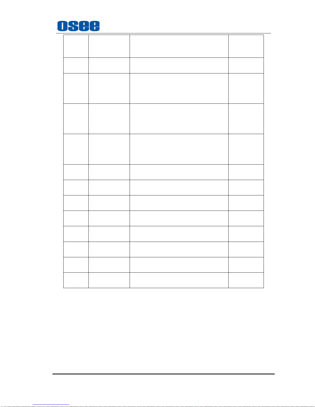
Tab. 3-1 Bank SW1 Function Setting
SW1
Position Function Options
(The position of toggling SW2:
SW2 is toggled down.) Default
0 Select mode
0 :625
1 :525
2 :AUTO SELECT
(auto recognition)
Notes:
The modes above will cycle between: 0, 1
and 2, when SW2 is toggled repeatedly.
*AUTO
SELECT
1 Control mode
0:BYPASS mode
(when it is selected , BYPASS LED lamp in
the module will also light in green)
*AUTO

VAC6840N Video & Audio 2X1 Switcher Operating Manual
Specifications are subject to change without notice. —7—
SW1
Position Function Options
(The position of toggling SW2:
SW2 is toggled down.) Default
1:AUTO mode
(when it is selected , AUTO LED lamp in
the module will also light in green)
2:MANUAL mode
Notes:
* When the lamps of BYPASS and AUTO
are all off, the control mode changes to
MANUAL mode.
*The modes above will cycle between: 0, 1
and 2, when SW2 is toggled repeatedly.
*When “AUTO mode“ is selected, the
operation of AUTO SELECT function can be
based on the “ENABLE” set of “Video loss
switch” or “Low level alarm” or “High level
alarm”.
2 Select output
mode
0:
Select input source 1 as output
1:
Select input source 2 as output
Notes:
* When the LED control mode is in auto
mode, the input source can not be selected by
manual.
*The modes above will cycle between: 0 and
1, when SW2 is toggled repeatedly.
*SOURCE 1
3 Auto switching
mode
0:(SW2 is toggled down.)
When one selected input source fails (E.g. 1),
it will automatically switch to select the other
normal input source (E.g. 2). Even though the
original input source 1 returns to normal, the
source 2 will retain.
1:(SW2 is toggled up.)
When one selected input source fails (E.g. 1),
it will automatically switch to select the other
normal input source (E.g. 2). Once the
original input source 1 returns to normal, it
will immediately switch back to select source
1, even though the source 2 works well or is
just being selected.
4 Video loss
switch
0:DISABLE
(SW2 is toggled down.)*ENABLE
VAC6840N Video & Audio 2X1 Switcher Operating Manual
Specifications are subject to change without notice. —8—
SW1
Position Function Options
(The position of toggling SW2:
SW2 is toggled down.) Default
1:ENABLE
(SW2 is toggled up.)
5 Mode auto select
0:DISABLE
(SW2 is toggled down.)
1:ENABLE
(SW2 is toggled up.)
6 Low level alarm
0:DISABLE
(SW2 is toggled down.)
1:ENABLE
(SW2 is toggled up.)
7 High level alarm
0:DISABLE
(SW2 is toggled down.)
1:ENABLE
(SW2 is toggled up.)
8 Reserve
9 Reserve
A Reserve
B Reserve
C Reserve
D Reserve
E Reserve
F default Down/up: set all into default
Note the following when setting parameters:
Judge the validity of the input signal and the reference signal by checking the ERROR.
To keep SW2 at the position of “UP” or “DOWN”, the continuous adjustment can be
achieved.
To return back to default status:rotate the SW1 to “0”; toggle the SW2 UP.
When the video output signal changes, the audio output signal, which adapts to the video
output signal, will also change.

VAC6840N Video & Audio 2X1 Switcher Operating Manual
Specifications are subject to change without notice. —9—
3.3 Description of LED Indicator
Tab.3-2 Description of LED Indicator
LED Indicator Color Description
POWER Green On: Power is supplied.
BY PASS Green On: work in BYPASS mode (bypass when power-down).
Off: Not work in BYPASS mode.
AUTO Green
On: work in AUTO mode.
Off: Not work in AUTO mode.
OUT1 Green
On: choose the channel 1 input signal as output
Off: not choose the channel 1 input signal as output
OUT2 Green
On: choose the channel 2 input signal as output
Off: not choose the channel 2 input signal as output
1ER Red
On: the channel 1 input signal does not work in normal;
Off: the channel 1 input signal works in normal.
2ER Red
On: the channel 2 input signal does not work in normal;
Off: the channel 2 input signal works in normal.
Chapter 4 Specifications
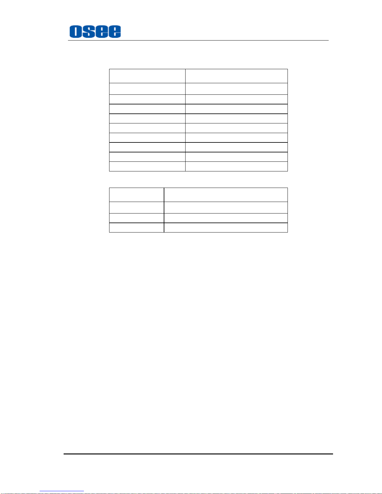
4.1 Analog Composite Video
Table 4-1 Analog Composite Video Specifications
Item Parameter
Standards NTSC, PAL-B
Connector BNC(IEC 169-8)
Impedance 75Ω
Return Loss >40 dB to 5.75 MHz
Quantization 12 bits
Frequency response ±0.15 dB to 5.5 MHz
Differential Gain <1%(typical value<0.5%)
Differential Phase <1°(typical value <0.5°)
DC offset ±5 mV
Chrominance Luminance Delay <1.5 ns
Chrominance Luminance Gain ±1.5%
Output Impedance 75Ω
K factor <0.5%
Line Time Distortion 0.1%
C/N >60 dB
VAC6840N Video & Audio 2X1 Switcher Operating Manual
Specifications are subject to change without notice. —10—
4.2 Analog Audio
Tab. 4-2 Analog Audio Input Specifications
Item Parameter
connector 3-pin audio connector
Standard Electronic, balanced
Output level range +18dBu to +28dBu
Maximum output level 0dBFS = +28dBu
Impedance 66Ω
THD+N >85 dB @ 1 kHz,-1dBFS = 23dBu
Crosstalk >95 dB,20 Hz to 20 kHz
Frequency response <±0.04dB @ 0dBFS, 20 Hz to 20 kHz
C/N >100 dB @ 0dBFS
4.3 Power consumption
Item Parameter
Power: 2.4W
Positive rail: 350 mA
Negative rail: 20 mA
Note: Specifications are subject to change without notice

VAC6840N Video & Audio 2X1 Switcher Operating Manual
Specifications are subject to change without notice. —11—
Chapter 5 Warranty for osee product
5.1 What the warranty covers:
osee warrants its products to be free from defects in material and workmanship during the warranty
period of two years from purchase date. If a product proves to be defective in material or workmanship
during the warranty period, osee will, at its sole option, repair or replace the product with a similar
product. The replacement unit will be covered by the balance of the time remaining on the customer’s
original limited warranty.
No sales personnel of the seller or any other person is authorized to make any warranties other than
those described above, or to extend the duration of any warranties on behalf of osee, beyond the time
period describe above.
This warranty is extended to the first consumer only, and proof of purchase is necessary to honor the
warranty. If there is no proof of purchase provided with a warranty claim, osee reserves the right not to
honor the warranty set forth above. Therefore, labor and parts may be charged to the consumer.
5.2 What the warranty does not cover:
1. Any product on which the serial number has been defaced, modified or removed.
2. Damage, deterioration or malfunction resulting from:
Accident, misuse, neglect, fire, water, lightning, or other acts of nature, unauthorized product
modification, or failure to follow instructions supplied with the product
Repair or attempted repair by anyone not authorized by osee
Any damage of the product due to shipment.
Removal or installation of the product.
Causes external to the product, such as electric power fluctuations or failure.
Use of supplies or parts not meeting osee product’s specifications.
Normal wear and tear.
Any other cause which does not relate to a product defect.
Table of contents
Other OSEE Switch manuals


Popular Switch manuals by other brands

Optical Systems Design
Optical Systems Design OSD2054P Series Operator's manual

Versa Technology
Versa Technology VX-IGP-1204F Quick installation guide

CYP
CYP CSC-6030CVE Operation manual

Avocent
Avocent SwitchView IP 1020 Installer/user guide

Roland
Roland V-40HD Specifications

TRENDnet
TRENDnet TE100-S5Pplus Quick installation guide


