Viessmann 6840 User manual
6840
H0 Schaltkontakt
(Magnetschalter)
H0 Switching contact
(magnetic switch)
Bedienungsanleitung
Operation Manual
DE
1
Modellbauartikel, kein Spielzeug! Nicht geeignet für
Kinder unter 14 Jahren! Anleitung aufbewahren!
Model building item, not a toy! Not suitable for children
under the age of 14 years! Keep these instructions!
Ce n’est pas un jouet! Ne convient pas aux enfants de
moins de 14 ans! Conservez cette notice d’instructions!
Não é um brinquedo! Não aconselhável para menores
de 14 anos! Conservar o manual de instruções!
Modelbouwartikel, geen speelgoed! Niet geschikt voor
kinderen onder 14 jaar! Gebruiksaanwijzing bewaren!
Articolo di modellismo, non è un giocattolo! Non adat-
to a bambini al di sotto dei 14 anni! Conservare istruzioni
per l’uso!
Artículo para modelismo ¡No es un juguete! No reco-
mendado para menores de 14 años! Conserva las inst-
rucciones de servicio!
DE
EN
FR
NL
IT
ES
PT
1. Wichtige Hinweise
Bitte lesen Sie vor der ersten Anwendung des Produk-
tes bzw. dessen Einbau diese Bedienungsanleitung
aufmerksam durch und bewahren Sie diese auf. Sie
ist Teil des Produktes.
1.1 Sicherheitshinweise
Vorsicht:
Verletzungsgefahr!
Aufgrund der detaillierten Abbildung des Originals
bzw. der vorgesehenen Verwendung kann das Pro-
dukt Spitzen, Kanten und abbruchgefährdete Teile
aufweisen. Für die Montage sind Werkzeuge nötig.
Stromschlaggefahr!
Die Anschlussdrähte niemals in eine Steckdose
einführen! Verwendetes Versorgungsgerät (Trans-
formator, Netzteil) regelmäßig auf Schäden über-
prüfen. Bei Schäden am Versorgungsgerät dieses
keinesfalls benutzen!
Alle Anschluss- und Montagearbeiten nur bei abge-
schalteter Betriebsspannung durchführen!
Ausschließlich nach VDE/EN gefertigte Modellbahn-
transformatoren verwenden!
Stromquellen unbedingt so absichern, dass es bei
einem Kurzschluss nicht zum Kabelbrand kommen
kann.
1.2 Das Produkt richtig verwenden
Dieses Produkt ist bestimmt:
- Zum Einbau in Modelleisenbahnanlagen und
Dioramen.
- Zum Anschluss an einen Modellbahntransformator
(z. B. Art. 5200) bzw. an eine Modellbahnsteuerung
mit zugelassener Betriebsspannung.
- Zum Betrieb in trockenen Räumen.
Jeder darüber hinausgehende Gebrauch gilt als nicht
bestimmungsgemäß. Für daraus resultierende Schäden
haftet der Hersteller nicht.
1.3 Packungsinhalt überprüfen
Kontrollieren Sie den Lieferumfang auf Vollständigkeit:
- Schaltkontakt mit Anschlusskabel
- 2 Unterlegstücke
- Schraube
- Anleitung

2
2. Einleitung
Der Viessmann-Schaltkontakt Art. 6840 ist ein be-
rührungsfreier Magnetschalter zum Auslösen von
Schaltvorgängen durch den fahrenden Zug. Er wird
direkt im Gleis montiert und ist sowohl mit Zwei- als
auch mit Dreileitergleisen verwendbar. Betätigt wird der
Schaltkontakt berührungsfrei durch Fahrzeugmagnete
(z. B. Art. 6841). Diese können an fast allen H0-Schie-
nenfahrzeugen angebracht werden und ermöglichen,
dass fahrende Züge Weichen oder Signale schalten
oder Rückmeldungen beim Betrieb eines Digitalsys-
tems auslösen.
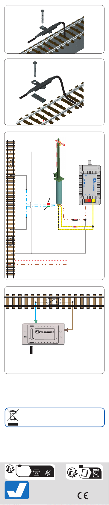
3. Einbau
Der Schaltkontakt kann durch die Öffnung des Befes-
tigungssteges am Gleis angeschraubt werden (Abb.
1). Bei Gleisen ohne Bettung sind die beiliegenden
Unterlegstücke zu verwenden (Abb. 2). Hierbei ist das
dünnere für Fleischmann und das dickere für bettungs-
lose Gleise aller anderen Hersteller entworfen worden.
Die Montage im Bogen ist nur für Radien ab 358 mm
zulässig.
4. Anschluss
4.1 Anschluss der Schaltkontakte
Nachfolgend werden einige Möglichkeiten zur Ver-
wendung der Schaltkontakte dargestellt. Es ist zu
beachten, dass an eine Kontakteinheit jeweils nur
ein Antrieb angeschlossen werden darf, da es sonst
zu einer Überlastung und somit zur Zerstörung des
Schaltkontaktes kommt.
Ein Kabel des Schaltkontaktes wird mit einem Pol des
Wechselstromausganges eines handelsüblichen Mo-
dellbahntransformators verbunden. Das andere Kabel
ist mit einem der blauen Kabel des zu schaltenden
Magnetartikels zu verbinden.
4.2 Ansteuerung eines Signals
Schließen Sie das gewünschte Signal gemäß Abb. 3
an.
5. Betrieb mit Digitalsystemen
Beim Zugbetrieb mit einem Schaltkontakt ist darauf
zu achten, dass das Fahrzeug nicht unmittelbar über
einem solchen zum Stehen kommt. Der so entstehende
Dauerkontakt könnte zu einem Verschmoren von elekt-
romagnetischen Antriebsspulen führen.
Der Abstand zwischen Schaltkontakt und Magnet muss
zwischen zwei und fünf Millimetern betragen. Dies ist
notwendig, um eine ausreichende Magnetwirkung ohne
Magnetisierung des Gleiskörpers sicherzustellen. Sollte
die Magnetkraft nicht ausreichen, können zwei Magnete
hintereinander montiert werden.
6. Technische Daten
Maximale Schaltspannung: 24 V AC~ / DC=
Kontaktbelastbarkeit: 2 A
1. Important information
Please read this manual completely and attentively
before using the product for the first time. Keep this
manual. It is part of the product.
1.1 Safety instructions
Caution:
Risk of injury!
Due to the detailed reproduction of the original and
the intended use, this product can have peaks,
edges and breakable parts. Tools are required for
installation.
Electrical hazard!
Never put the connecting wires into a power socket!
Regularly examine the transformer for damage. In
case of any damage, do not use the transformer.
Make sure that the power supply is switched off
when you mount the device and connect the cables!
Only use VDE/EN tested special model train trans-
formers for the power supply!
The power sources must be protected to avoid the
risk of burning cables.
EN

3
1.2 Using the product for its correct
purpose
This product is intended:
- For installation in model train layouts and dioramas.
- Forconnectiontoanauthorizedmodeltraintransformer
(e. g. item 5200).
- For operation in dry rooms only.
Using the product for any other purpose is not approved
and is considered inappropriate. The manufacturer is
not responsible for any damage resulting from the im-
proper use of this product.
1.3 Checking the package contents
Check the contents of the package for completeness:
- Switching contact with connection cable
- 2 underlay pieces
- Screw
- Manual
2. Introduction
The switching contact item 6840 from Viessmann is
able to trigger switches by the running train. It is us-
able in combination with two- and three-rail tracks and
can be mounted directly on the tracks. The contact is
activated by a vehicle magnet (e. g. Viessmann item
6841) without being touched. It can be mounted under
nearly all H0 track vehicles and makes it possible to
switch turnouts and signals or to give a feedback to a
digital system.
3. Mounting
The switching contact can be screwed onto the tracks
through the hole of the fastening bar (fig. 1). For tracks
without ballast, the enclosed underlay pieces have
to be used (fig. 2). The smaller one is suitable for
Fleischmann tracks and the bigger one for tracks with-
out ballast from all other manufacturers. Please note
that the mounting in a curve is only permitted for radii
from 358 mm upwards.
4. Connection
4.1 How to connect the switching contacts
The following pictures show several possibilities for
using the switching contacts. Please note, that only one
drive can be connected to each contact unit. Otherwise
there can be an overload, so that the contacts can be
destroyed.
One wire of the switching contact has to be connected
to one pole of the alternating current exit of a model
train transformer. The other wire has to be connected
to one of the blue wires of the magnetic article.
4.2 Controlling of a semaphore
Connect the signal as shown in fig. 3.
5. Operation with digital systems
If you operate with switching contacts it is important,
that the vehicle does not stop directly above a contact.
By a permanent contact the electromagnetic spools
could burn.
The distance between the switching contact and the
magnet has to be between two and five millimeters.
This is neccesary to guarantee a sufficient magnetic
power and to guarantee, that the tracks do not get
magnetic. If the magnetic power is not strong enough,
two magnets can be mounted in a row.
6. Technical data
Max. switching voltage: 24 V AC~ / DC=
Max. contact load: 2 A
Viessmann
Modelltec
hnik GmbH
Bahnhofstraße 2a
D - 35116 Hatzfeld-Reddighausen
+49 6452 9340-0
www.viessmann-modell.de
Made in Europe
Entsorgen Sie dieses Produkt nicht über den (unsortierten)
Hausmüll, sondern führen Sie es der Wiederverwertung zu.
Do not dispose of this product through (unsorted) domestic
waste, supply it to recycling instead.
Subject to change without prior notice. No liability for mistakes and printing
errors.
You will find the latest version of the manual on the Viessmann website using
the item number.
Änderungen vorbehalten. Keine Haftung für Druckfehler und Irrtümer.
Die aktuelle Version der Anleitung finden Sie auf der Viessmann Homepage
unter der Artikelnummer.
98668
Stand 06/sw
03/2023
Ho/Kf
4
FR
T
T
16
1514
13
1211
109
1
2
3
4
5
67
8
Rückmeldedecoder
5217
Richtung Digitalzentrale
z. B. / e. g. 5217
zur Digitalzentrale
to the digital command station
Sekundär
0-10-16 V~
16 V
Primär
230 V~
Gefertigtnach
VDE0570
EN61558
Lichttransformator
5200
Nur für trockene Räume
Primär 230 V 50 - 60 Hz
Sekundär max. 3,25 A52 VA
ta 25°CIP 40
10 V
0 V
rote Markierung
red marker
grüne Markierung
green marker
braun /
brown
gelb / yellow
rot / red
braun / brown
Fahrstrom
track current
z. B. / e. g.
4470/4500/
4700/9500 z. B. / e. g. 5200
Abb. 1
Abb. 2
Abb. 4
Abb. 3
Fig. 1
Fig. 2
Fig. 4
Fig. 3
Points de collecte sur www.quefairedemesdechets.fr
À DÉPOSER
EN MAGASIN À DÉPOSER
EN DÉCHÈTERIE
OU
Cet modéle
se recycle
FR
Table of contents
Languages:
Other Viessmann Switch manuals


